

ISO 4918
(Main)Resilient, textile, laminate and modular mechanical locked floor coverings — Castor chair test
- Abstract
ISO 4918:2016 specifies methods for determining the change of appearance and stability of a textile floor covering or any damage caused by detachment of layers, opening of joints, or crazing of a resilient or laminate floor covering under the movement of a castor chair.
- Status
- Not Published
- Technical Committee
- ISO/TC 219 - Floor coverings
- Drafting Committee
- ISO/TC 219 - Floor coverings
- Current Stage
- 6000 - International Standard under publication
- Start Date
- 01-Oct-2026
- Completion Date
- 05-Sep-2026
Buy Documents


ISO/FDIS 4918 - Resilient, textile, laminate and modular mechanical locked floor coverings — Castor chair test

REDLINE ISO/FDIS 4918 - Resilient, textile, laminate and modular mechanical locked floor coverings — Castor chair test

ISO/FDIS 4918 - Revêtements de sol textiles, résilients ou stratifiés — Essai à l'appareil à roulettes
ISO 4918 is an ISO standard for the castor chair test on resilient, textile, laminate and modular mechanical locked floor coverings. It specifies how to assess change of appearance, structural stability and visible damage when a swivel castor chair moves over a floor covering, so laboratories, manufacturers and specifiers can compare products under the same test conditions.
What does ISO 4918 specify?
ISO 4918 specifies the test method, specimen preparation, conditioning, apparatus, assessment and test report content for castor chair testing of textile floor coverings and of resilient, laminate and modular mechanical locked floor coverings. The document is organized into clauses 1 to 12, with Annex A as an informative example of specimen assembly.
| Annex | What it covers |
|---|---|
| Annex A | An example of how to assemble and clamp specimens in or out of the device |
The scope covers change of appearance and stability for textile floor coverings, and damage such as detachment of layers, opening of joints, cracking or crazing for resilient, laminate and modular mechanical locked floor coverings. In practice, that means the standard is used to see how a floor reacts to repeated chair movement, not just to static load.
What are the key requirements of ISO 4918?
ISO 4918 requires a controlled rotating-platform test in which three castors travel over the specimen in epicyclical paths with repeated changes of direction, stops and starts. That matters because the test is meant to reproduce the combined rolling, turning and stress concentration created by swivel chairs.
Test outcomes depend on the floor covering type
For textile floor coverings, ISO 4918 provides three assessment routes. Test A looks at appearance after 5 000 cycles and 25 000 cycles, Test B looks at colour change after 750 cycles, and Test C looks at deterioration after 10 000 cycles or 25 000 cycles. Assessments use ISO 9405 or ASTM D7330, and colour change is judged with grey scales.
For resilient, laminate and modular mechanical locked floor coverings, ISO 4918 focuses on visible structural damage after testing. The assessor records cracks, crazing, detachment of layers and, for products with mechanical locking systems, opening or ledging of joints. Flattening and gloss change are ignored, so the reader knows the standard is looking for real damage rather than simple surface polishing.
Specimens must represent the installed product
ISO 4918 requires textile specimens to be taken in accordance with ISO 1957. For resilient floor coverings without a mechanical locking system, the test area must include joints in the path of the castors; for laminate and modular mechanical locked floor coverings, the assembled test area must include the locking variations in the castor path and follow the manufacturer’s instructions. This is important because the result depends on how the product is actually installed.
Conditioning and mounting are controlled
ISO 4918 conditions textile specimens at 65 % relative humidity and 20 °C for at least 24 h, and resilient, laminate and modular mechanical locked floor coverings at 50 % relative humidity and 23 °C for at least 24 h. The specimens must then be fixed securely, with movement prevented but vertical force kept to a minimum. If an underlay is used or prescribed, it must be included in the test assembly.
The mounting rules matter because a loose or over-compressed assembly can hide the real behaviour of the floor. ISO 4918 also limits underlay compression to a maximum of 0,5 mm and requires the tested assembly to stay level, with all three castor wheels sharing the load.
The apparatus and castors are defined
ISO 4918 specifies a rotating test platform, a castor assembly offset from the platform centre, a reversing drive and a suction device. The platform rotates at 19 ± 2 min-1 and the castor assembly at 50 ± 5 min-1, with a stop and reversal after 180 ± 20 s. The castor assembly is loaded to a total of 90 ± 2 kg equally across three castors.
The castors themselves are controlled too. ISO 4918 uses Type H castors for textile floor coverings, and Type H or Type W castors for resilient, laminate and modular mechanical locked floor coverings, depending on the product standard or sponsor instruction. That gives comparable wear conditions from one test to another.
Assessment and reporting are part of the method
ISO 4918 requires appearance assessment under defined viewing conditions, including illumination for non-textile products. For textile floor coverings, the standard also uses a castor chair index based on the median results after 5 000 cycles and 25 000 cycles. In practice, that index gives a single classification-oriented value from the main appearance results.
The test report must identify the product, the wheels used, any adhesive or underlay, the fixing method, the results, any deviations and the test date. For textile floor coverings, it must also state whether Test A, B or C was used and the relevant appearance, colour or structural result.
What terms does ISO 4918 define?
ISO 4918 uses terminology from ISO 2424, EN 16511 and EN 12466, and it defines some key terms for the test itself.
- Crazing - fine random cracks on the surface of a floor covering, usually caused by stress; in this test it is one of the visible damage modes recorded for resilient and laminate products.
- Modular mechanical locked floor coverings (MMF) - modular floor coverings with mechanical locking systems that are assembled for testing according to the manufacturer’s instructions.
- Castor chair index - a calculated value used with textile floor coverings to combine the appearance assessments after 5 000 cycles and 25 000 cycles.
- Appearance retention - the condition of a textile floor covering after testing, judged by comparing the fatigued specimen with an unfatigued reference.
- Structural integrity - the absence or presence of physical damage such as delamination, tearing, flaking or loss of cohesion after cycling.
- Type H castors - hard-tread castors specified for the test of textile and some resilient, laminate and modular mechanical locked floor coverings.
- Type W castors - soft-tread castors specified for testing resilient, laminate and modular mechanical locked floor coverings.
Who uses ISO 4918?
ISO 4918 is used by flooring manufacturers, test laboratories, quality teams and product specifiers who need a repeatable way to check resistance to castor chair action. It is relevant to the textile flooring sector and to resilient, laminate and modular mechanical locked floor coverings, especially for product development, type testing, quality control and procurement decisions.
Buyers and technical reviewers use it to compare candidate products on the same basis. Manufacturers use it to document durability claims and to check whether a product’s joints, layers or surface finish remain stable under chair movement.
What changed in ISO 4918 from the previous edition?
This third edition cancels and replaces ISO 4918:2016/Amd 1:2018, and it is technically revised. The stated changes are revised information about the machine, revised fastening methods, and added methods for testing modular mechanical locked floor coverings (MMF).
Which standards are used with ISO 4918?
ISO 4918 relies on several normative references and related standards to define atmosphere, sampling, vocabulary and assessment.
- ISO 139:2005/AMD1:2011 - gives the standard atmosphere for conditioning and testing textiles.
- ISO 1957 - defines selection and cutting of specimens for physical tests on machine-made textile floor coverings.
- ISO 2424 - provides vocabulary for textile floor coverings.
- ISO 9405 - gives the method for assessing changes in appearance of textile floor coverings.
- EN 12466 - provides vocabulary for resilient floor coverings.
- EN 12529 - specifies castors for swivel chairs, which ISO 4918 uses to define the test wheels.
- EN 16511 - provides specification, requirements and test method context for modular mechanical locked floor coverings.
- ASTM D7330 - offers an alternative method for assessing surface appearance change in pile floor coverings using standard reference scales.
What does the ISO 4918 document contain?
ISO 4918 contains the test principle, the apparatus description, the specimen selection rules, conditioning requirements, step-by-step procedures and the assessment and reporting requirements. It also includes detailed figures for the test platform, castor arrangement, joint positions, specimen fixation and the evaluation template.
The document gives the practical setup needed to run the test consistently, including the rotating platform, castor assembly, suction device, lifting device and measurement checks for levelness and wheel contact. It also includes the calculation approach for the castor chair index and the reporting items needed for traceable test records.
Annex A provides an informative example of specimen assembly using a side ring and clamping ring. That helps users understand how to secure samples without letting them shift during testing.
Relations
- Effective Date
- 12-Feb-2026
- Effective Date
- 03-Sep-2022
- Effective Date
- 03-Sep-2022
Buy Documents
ISO/FDIS 4918 - Resilient, textile, laminate and modular mechanical locked floor coverings — Castor chair test
REDLINE ISO/FDIS 4918 - Resilient, textile, laminate and modular mechanical locked floor coverings — Castor chair test
ISO/FDIS 4918 - Revêtements de sol textiles, résilients ou stratifiés — Essai à l'appareil à roulettes
Frequently Asked Questions
ISO 4918 is a draft published by the International Organization for Standardization (ISO). Its full title is "Resilient, textile, laminate and modular mechanical locked floor coverings — Castor chair test". This standard covers: ISO 4918:2016 specifies methods for determining the change of appearance and stability of a textile floor covering or any damage caused by detachment of layers, opening of joints, or crazing of a resilient or laminate floor covering under the movement of a castor chair.
ISO 4918:2016 specifies methods for determining the change of appearance and stability of a textile floor covering or any damage caused by detachment of layers, opening of joints, or crazing of a resilient or laminate floor covering under the movement of a castor chair.
ISO 4918 is classified under the following ICS (International Classification for Standards) categories: 97.150 - Floor coverings. The ICS classification helps identify the subject area and facilitates finding related standards.
ISO 4918 has the following relationships with other standards: It is inter standard links to FprEN ISO 4918, ISO 4918:2016, ISO 4918:2016/Amd 1:2018. Understanding these relationships helps ensure you are using the most current and applicable version of the standard.
ISO 4918 is available in PDF format for immediate download after purchase. The document can be added to your cart and obtained through the secure checkout process. Digital delivery ensures instant access to the complete standard document.
Standards Content (Sample)
FINAL DRAFT
International
Standard
ISO/FDIS 4918
ISO/TC 219
Resilient, textile, laminate and
Secretariat: NBN
modular mechanical locked floor
Voting begins on:
coverings — Castor chair test
2026-08-05
Revêtements de sol textiles, résilients ou stratifiés — Essai à
Voting terminates on:
l'appareil à roulettes
2026-09-30
RECIPIENTS OF THIS DRAFT ARE INVITED TO SUBMIT,
WITH THEIR COMMENTS, NOTIFICATION OF ANY
RELEVANT PATENT RIGHTS OF WHICH THEY ARE AWARE
AND TO PROVIDE SUPPOR TING DOCUMENTATION.
IN ADDITION TO THEIR EVALUATION AS
BEING ACCEPTABLE FOR INDUSTRIAL, TECHNO
ISO/CEN PARALLEL PROCESSING LOGICAL, COMMERCIAL AND USER PURPOSES, DRAFT
INTERNATIONAL STANDARDS MAY ON OCCASION HAVE
TO BE CONSIDERED IN THE LIGHT OF THEIR POTENTIAL
TO BECOME STAN DARDS TO WHICH REFERENCE MAY BE
MADE IN NATIONAL REGULATIONS.
Reference number
ISO/FDIS 4918:2026(en) © ISO 2026
FINAL DRAFT
ISO/FDIS 4918:2026(en)
International
Standard
ISO/FDIS 4918
ISO/TC 219
Resilient, textile, laminate and
Secretariat: NBN
modular mechanical locked floor
Voting begins on:
coverings — Castor chair test
Revêtements de sol textiles, résilients ou stratifiés — Essai à
Voting terminates on:
l'appareil à roulettes
RECIPIENTS OF THIS DRAFT ARE INVITED TO SUBMIT,
WITH THEIR COMMENTS, NOTIFICATION OF ANY
RELEVANT PATENT RIGHTS OF WHICH THEY ARE AWARE
AND TO PROVIDE SUPPOR TING DOCUMENTATION.
© ISO 2026
IN ADDITION TO THEIR EVALUATION AS
All rights reserved. Unless otherwise specified, or required in the context of its implementation, no part of this publication may
BEING ACCEPTABLE FOR INDUSTRIAL, TECHNO
ISO/CEN PARALLEL PROCESSING
LOGICAL, COMMERCIAL AND USER PURPOSES, DRAFT
be reproduced or utilized otherwise in any form or by any means, electronic or mechanical, including photocopying, or posting on
INTERNATIONAL STANDARDS MAY ON OCCASION HAVE
the internet or an intranet, without prior written permission. Permission can be requested from either ISO at the address below
TO BE CONSIDERED IN THE LIGHT OF THEIR POTENTIAL
or ISO’s member body in the country of the requester.
TO BECOME STAN DARDS TO WHICH REFERENCE MAY BE
MADE IN NATIONAL REGULATIONS.
ISO copyright office
CP 401 • Ch. de Blandonnet 8
CH-1214 Vernier, Geneva
Phone: +41 22 749 01 11
Email: copyright@iso.org
Website: www.iso.org
Published in Switzerland Reference number
ISO/FDIS 4918:2026(en) © ISO 2026
ii
ISO/FDIS 4918:2026(en)
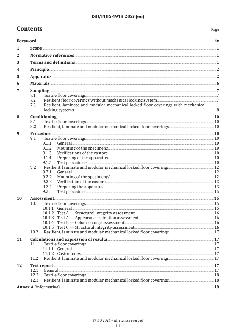
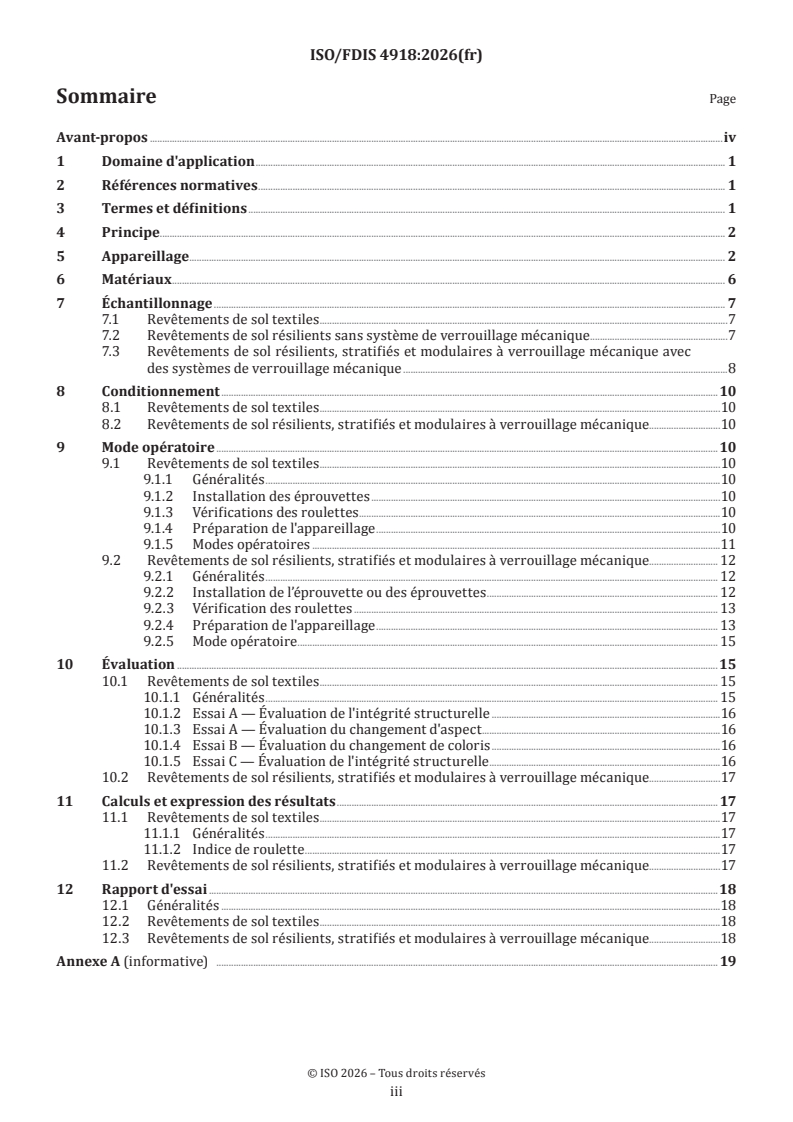
Contents Page
Foreword .iv
1 Scope . 1
2 Normative references . 1
3 Terms and definitions . 1
4 Principle . 2
5 Apparatus . 2
6 Materials . 6
7 Sampling . 7
7.1 Textile floor coverings .7
7.2 Resilient floor coverings without mechanical locking system .7
7.3 Resilient, laminate and modular mechanical locked floor coverings with mechanical
locking systems . .8
8 Conditioning . 10
8.1 Textile floor coverings .10
8.2 Resilient, laminate and modular mechanical locked floor coverings .10
9 Procedure .10
9.1 Textile floor coverings .10
9.1.1 General .10
9.1.2 Mounting of the specimens .10
9.1.3 Verifications of the castors .10
9.1.4 Preparing of the apparatus .10
9.1.5 Test procedures .10
9.2 Resilient, laminate and modular mechanical locked floor coverings . 12
9.2.1 General . 12
9.2.2 Mounting of the specimen(s) . 12
9.2.3 Verification of the castors . 13
9.2.4 Preparing the apparatus . 13
9.2.5 Test procedure. 15
10 Assessment . .15
10.1 Textile floor coverings . 15
10.1.1 General . 15
10.1.2 Test A — Structural integrity assessment .16
10.1.3 Test A — Appearance retention assessment .16
10.1.4 Test B — Colour change assessment .16
10.1.5 Test C — Structural integrity assessment .16
10.2 Resilient, laminate and modular mechanical locked floor coverings .17
11 Calculations and expression of results . 17
11.1 Textile floor coverings .17
11.1.1 General .17
11.1.2 Castor index .17
11.2 Resilient, laminate and modular mechanical locked floor coverings .17
12 Test report . 17
12.1 General .17
12.2 Textile floor coverings .18
12.3 Resilient, laminate and modular mechanical locked floor coverings .18
Annex A (informative) . 19
iii
ISO/FDIS 4918:2026(en)
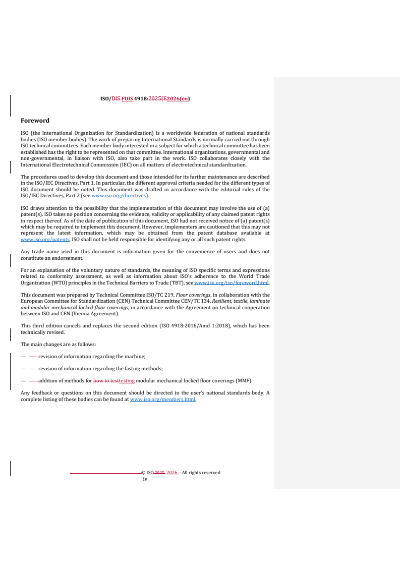
Foreword
ISO (the International Organization for Standardization) is a worldwide federation of national standards
bodies (ISO member bodies). The work of preparing International Standards is normally carried out through
ISO technical committees. Each member body interested in a subject for which a technical committee
has been established has the right to be represented on that committee. International organizations,
governmental and non-governmental, in liaison with ISO, also take part in the work. ISO collaborates closely
with the International Electrotechnical Commission (IEC) on all matters of electrotechnical standardization.
The procedures used to develop this document and those intended for its further maintenance are described
in the ISO/IEC Directives, Part 1. In particular, the different approval criteria needed for the different types
of ISO document should be noted. This document was drafted in accordance with the editorial rules of the
ISO/IEC Directives, Part 2 (see www.iso.org/directives).
ISO draws attention to the possibility that the implementation of this document may involve the use of (a)
patent(s). ISO takes no position concerning the evidence, validity or applicability of any claimed patent
rights in respect thereof. As of the date of publication of this document, ISO had not received notice of (a)
patent(s) which may be required to implement this document. However, implementers are cautioned that
this may not represent the latest information, which may be obtained from the patent database available at
www.iso.org/patents. ISO shall not be held responsible for identifying any or all such patent rights.
Any trade name used in this document is information given for the convenience of users and does not
constitute an endorsement.
For an explanation of the voluntary nature of standards, the meaning of ISO specific terms and expressions
related to conformity assessment, as well as information about ISO's adherence to the World Trade
Organization (WTO) principles in the Technical Barriers to Trade (TBT), see www.iso.org/iso/foreword.html.
This document was prepared by Technical Committee ISO/TC 219, Floor coverings, in collaboration with the
European Committee for Standardization (CEN) Technical Committee CEN/TC 134, Resilient, textile, laminate
and modular mechanical locked floor coverings, in accordance with the Agreement on technical cooperation
between ISO and CEN (Vienna Agreement).
This third edition cancels and replaces the second edition (ISO 4918:2016/Amd 1:2018), which has been
technically revised.
The main changes are as follows:
— revision of information regarding the machine;
— revision of information regarding the fasting methods;
— addition of methods for testing modular mechanical locked floor coverings (MMF).
Any feedback or questions on this document should be directed to the user’s national standards body. A
complete listing of these bodies can be found at www.iso.org/members.html.
iv
FINAL DRAFT International Standard ISO/FDIS 4918:2026(en)
Resilient, textile, laminate and modular mechanical locked
floor coverings — Castor chair test
1 Scope
This document specifies methods for determining the change of appearance and stability of a textile floor
coverings or any damage caused by detachment of layers, opening of joints, cracks, or crazing of a resilient,
laminate or modular mechanical locked floor coverings under the movement of a swivel castor chair.
2 Normative references
The following documents are referred to in the text in such a way that some or all of their content constitutes
requirements of this document. For dated references, only the edition cited applies. For undated references,
the latest edition of the referenced document (including any amendments) applies.
ISO 139:2005/AMD1:2 011, Textiles — Standard atmospheres for conditioning and testing
ISO 1957, Machine-made textile floor coverings — Selection and cutting of specimens for physical tests
ISO 2424, Textile floor coverings — Vocabulary
ISO 9405, Textile floor coverings — Assessment of changes in appearance
EN 12466, Resilient floor coverings — Vocabulary
EN 12529, Castors and wheels — Castors for furniture — Castors for swivel chairs — Requirements
EN 16511, Modular mechanical locked floor coverings (MMF) — Specification, requirements and test method for
multilayer modular panels for floating installation
ASTM D7330, Standard Test Method for Assessment of Surface Appearance Change in Pile Floor Coverings Using
Standard Reference Scales
3 Terms and definitions
For the purposes of this document, the terms and definitions given in ISO 2424, EN 16511, EN 12466 and the
following apply.
ISO and IEC maintain terminology databases for use in standardization at the following addresses:
— ISO Online browsing platform: available at https:// www .iso .org/ obp
— IEC Electropedia: available at https:// www .electropedia .org/
3.1
crazing
fine random cracks apparent in the surface of a floor coverings, generally caused by an applied stress acting
on the surface
Note 1 to entry: Applied stress can include, for example, sustained exposure to a rolling load.
ISO/FDIS 4918:2026(en)
4 Principle
A floor covering comprising one or more individual pieces with or without joint and treated or welded where
necessary, is submitted for a prescribed number of cycles to the action of three castors. The castors move in
epicyclical paths with multiple changes of direction, stops and starts, and the frequency of passage varies
from area to area.
For textile floor coverings, three different assessment methods are specified.
a) The change in appearance shall be assessed after 5 000 cycles and 25 000 cycles in accordance with
ISO 9405 (Test A) or ASTM D7330.
b) The change in colour shall be assessed by means of grey scales after 750 cycles in accordance with
ISO 9405 (Test B) or ASTM D7330.
c) The extent of deterioration shall be assessed after 10 000 cycles or 25 000 cycles (Test C).
For resilient, laminate or modular mechanical locked floor coverings, any damage to the specimen caused
during testing and visible as detachment of layers, opening of joints, cracking or crazing shall be assessed.
5 Apparatus
5.1 Rotating test platform
The rotating test platform on which the test specimen or the specimen support (5.9) together with the test
specimen is placed shall have a diameter of at least 795 mm (circular platform) or platform with a length
and width of at least 1 000 mm (square platform).
5.2 Castor assembly
This assembly comprises a vertical shaft, set in a bearing, and a plate on which the castors are mounted (see
Figure 1, item 1). This castor assembly is offset at a distance of (198 ± 1) mm from the centre of the rotating
test platform.
The three castors are each arranged concentrically at 120° intervals around the centre of the plate at a
distance of (130 ± 1) mm from the centre of the plate, and are free to rotate, so that they follow the rotation
of the castor assembly.
The tested area of the specimen is determined by the distance between the axes of revolution of the castor
chair assembly and the specimen table and by the distance of the castors from the centre of the plate. This
area is approximately 0,3 m .
ISO/FDIS 4918:2026(en)
Dimensions in millimetres
Key
1 shaft
2 distance >3 mm
3 load and or drive plate
4 castor mounting plate
5 chain
6 specimen
7 suction device with height regulation
8 rotating test platform
9 specimen support
Figure 1 — Typical castor chair apparatus
The castor assembly is loaded with additional weights to achieve a total load of (90 ± 2) kg equally divided
over the three castors.
The distance (under load) between the castor mounting plate and either the load or drive plate, or both,
shall be >3 mm.
ISO/FDIS 4918:2026(en)
Key
1 castor assembly
Figure 2 — Path of castors
5.3 Drive mechanism
The drive to the rotating test platform and to the castor assembly is interlocked and fitted with a reversing
mechanism. The number of cycles is set by means of a pre-set counter. The rotational speed of the rotating
-1 -1
platform shall be (19 ± 2) min and that of the castor assembly (50 ± 5) min .
After (180 ± 20) s of rotation, the platform shall stop and remain in the stop position for (5 ± 2) s, after which
time the direction of rotation of the rotating platform shall reverse.
The relationship between the rotational speed of the test platform and that of the castor assembly causes a
sharp reverse movement of the castors of about 160° at a point close to the outer edge of the stressed area
(see Figure 2).
5.4 Suction device
The suction capacity of the vacuum cleaner and the height of the suction device (see Figure 1, item 7) should
be able to remove all abrased material or dust in a way that the surface of the test specimen is always kept
clean during the test. A suction capacity of (30 ± 5) l/s is recommended to reach this requirement.
5.5 Castors
5.5.1 General
Single-wheel swivel castors shall be used having the following dimensions (see Figure 3):
a) diameter of the wheel: (50 ± 2) mm;
b) width of the wheel: (20 ± 2) mm;
c) radius of curvature, R, of castor tread: nominal 130 mm;
d) crank distance: (32 ± 2) mm.
The distance between any two castor mountings shall be (225 ± 5) mm.
ISO/FDIS 4918:2026(en)
Dimensions in millimetres
Figure 3 — Single-wheel swivel castors (nominal dimensions in mm)
1)
5.5.2 Type H castors conforming to EN 12529, suitable for resilient, textile, laminate and modular
mechanical locked floor coverings.
Type H castors shall have plain wheels and a hard tread. The castor treads shall be made from polyamide,
with a surface hardness of (95 ± 5) Shore A and shall be stored under exclusion of light. The wheels
shall be one colour over their entire surface. The surface of the castors shall be replaced after maximum
2 000 000 cycles of the rotating test platform. It is advisable to replace them all three.
The castor treads shall be examined after each test to verify that they are still smooth, without any deep
scoring or encrusted hard particles. The tread shall be replaced if the dimensions of the wheel fall outside
the tolerances given in 5.5.1.
2)
5.5.3 Type W castors conforming to EN 12529, suitable for resilient, laminate and modular mechanical
locked floor coverings.
Type W castors shall have resilient-tyred wheels and a soft tread. The castor treads shall be made from
polyurethane, with a surface hardness of (90 ± 5) Shore A and shall be stored under exclusion of light. The
surface of the castors shall be replaced after maximum 1 000 000 cycles of the test platform. It is advisable
to replace them all three.
1) An example of a commercially available Type H castor is from Quanz-Machinenbau GmbH. This information is given
for the convenience of users of this document and does not constitute an endorsement by ISO of this product.
2) An example of a commercially available castor product “Type W” is “Maxtech UAK050x20-Ø6,1” from TENTE
International GmbH. This information is given for the convenience of users of this document and does not constitute an
endorsement by ISO of this product.
ISO/FDIS 4918:2026(en)
The castor treads shall be examined after each test to verify that they are still smooth, without any deep
scoring or encrusted hard particles. The tread shall be replaced if the dimensions of the wheel fall outside
the tolerances given in 5.5.1.
5.6 Lifting device, to raise the castor assembly above the test platform when the apparatus is stationary.
5.7 Cycle counter, for setting the number of cycles of the test platform.
5.8 Fastening system
Flooring specimens shall be securely held in place on the specimen support (5.9) using glue, tape, or
other suitable means. For loose-laid installations, the panels, sheets and tiles shall be secured at the outer
perimeter using tape, which may include a flooring product and an underlayment, a hold down ring, an outer
ring, hold down clamps (see Annex A) or other suitable means to prevent specimens, from shifting during
the test. The vertical force should
...
Modular mechanical locked floor coverings
ISO/DIS FDIS 4918:2025(en)
ISO/TC 219/WG 4
Secretariat: NBN
Date: 2026-05-0307-22
Resilient, textile, laminate and modular mechanical locked floor
coverings — Castor chair test
Revêtements de sol textiles, résilients ou stratifiés — Essai à l'appareil à roulettes
FDIS stage
TThhiiss dr draafftt i iss susubbmmiitttteed d ttoo aa ppaarraallellel l vvoottee i inn IISSOO,, CCEEN.N.
ISO/DIS FDIS 4918:2025(E2026(en)
All rights reserved. Unless otherwise specified, or required in the context of its implementation, no part of this publication
may be reproduced or utilized otherwise in any form or by any means, electronic or mechanical, including photocopying,
or posting on the internet or an intranet, without prior written permission. Permission can be requested from either ISO
at the address below or ISO’s member body in the country of the requester.
ISO copyright office
CP 401 • Ch. de Blandonnet 8
CH-1214 Vernier, Geneva
Phone: + 41 22 749 01 11
EmailE-mail: copyright@iso.org
Website: www.iso.org
Published in Switzerland
ii
ISO/DIS FDIS 4918:20252026(en)
Contents
Foreword . iv
1 Scope . 1
2 Normative references . 1
3 Terms and definitions . 1
4 Principle . 2
5 Apparatus . 2
6 Materials. 9
7 Sampling . 9
7.1 Textile floor coverings . 9
7.2 Resilient floor coverings without mechanical locking system . 10
7.3 Resilient, laminate and modular mechanical locked floor coverings with mechanical
locking systems . 12
8 Conditioning . 14
8.1 Textile floor coverings . 14
8.2 Resilient, laminate and modular mechanical locked floor coverings . 14
9 Procedure . 14
9.1 Textile floor coverings . 14
9.2 Resilient, laminate and modular mechanical locked floor coverings . 16
10 Assessment . 21
10.1 Textile floor coverings . 21
10.2 Resilient, laminate and modular mechanical locked floor coverings . 23
11 Calculations and expression of results . 24
11.1 Textile floor coverings . 24
11.2 Resilient, laminate and modular mechanical locked floor coverings . 24
12 Test report . 24
12.1 General . 24
12.2 Textile floor coverings . 25
12.3 Resilient, laminate and modular mechanical locked floor coverings . 25
Annex A (informative) . 26
iii
ISO/DIS FDIS 4918:2025(E2026(en)
Foreword
ISO (the International Organization for Standardization) is a worldwide federation of national standards
bodies (ISO member bodies). The work of preparing International Standards is normally carried out through
ISO technical committees. Each member body interested in a subject for which a technical committee has been
established has the right to be represented on that committee. International organizations, governmental and
non-governmental, in liaison with ISO, also take part in the work. ISO collaborates closely with the
International Electrotechnical Commission (IEC) on all matters of electrotechnical standardization.
The procedures used to develop this document and those intended for its further maintenance are described
in the ISO/IEC Directives, Part 1. In particular, the different approval criteria needed for the different types of
ISO document should be noted. This document was drafted in accordance with the editorial rules of the
ISO/IEC Directives, Part 2 (see www.iso.org/directives).
ISO draws attention to the possibility that the implementation of this document may involve the use of (a)
patent(s). ISO takes no position concerning the evidence, validity or applicability of any claimed patent rights
in respect thereof. As of the date of publication of this document, ISO had not received notice of (a) patent(s)
which may be required to implement this document. However, implementers are cautioned that this may not
represent the latest information, which may be obtained from the patent database available at
www.iso.org/patents. ISO shall not be held responsible for identifying any or all such patent rights.
Any trade name used in this document is information given for the convenience of users and does not
constitute an endorsement.
For an explanation of the voluntary nature of standards, the meaning of ISO specific terms and expressions
related to conformity assessment, as well as information about ISO's adherence to the World Trade
Organization (WTO) principles in the Technical Barriers to Trade (TBT), see www.iso.org/iso/foreword.html.
This document was prepared by Technical Committee ISO/TC 219, Floor coverings, in collaboration with the
European Committee for Standardization (CEN) Technical Committee CEN/TC 134, Resilient, textile, laminate
and modular mechanical locked floor coverings, in accordance with the Agreement on technical cooperation
between ISO and CEN (Vienna Agreement).
This third edition cancels and replaces the second edition (ISO 4918:2016/Amd 1:2018), which has been
technically revised.
The main changes are as follows:
— — revision of information regarding the machine;
— — revision of information regarding the fasting methods;
— — addition of methods for how to testtesting modular mechanical locked floor coverings (MMF).
Any feedback or questions on this document should be directed to the user’s national standards body. A
complete listing of these bodies can be found at www.iso.org/members.html.
iv
DRAFT International Standard ISO/DIS 4918:2025(en)
Resilient, textile, laminate and modular mechanical locked floor
coverings — Castor chair test
1 Scope
This document specifies methods for determining the change of appearance and stability of a textile floor
coverings or any damage caused by detachment of layers, opening of joints, cracks, or crazing of a resilient,
laminate or modular mechanical locked floor coverings under the movement of a swivel castor chair.
2 Normative references
The following documents are referred to in the text in such a way that some or all of their content constitutes
requirements of this document. For dated references, only the edition cited applies. For undated references,
the latest edition of the referenced document (including any amendments) applies.
ISO 139:2005/AMD1:2011, Textiles — Standard atmospheres for conditioning and testing
ISO 1957, Machine-made textile floor coverings — Selection and cutting of specimens for physical tests
ISO 2424, Textile floor coverings — Vocabulary
ISO 9405, Textile floor coverings — Assessment of changes in appearance
EN 12466, Resilient floor coverings — Vocabulary
EN 12529, Castors and wheels — Castors for furniture — Castors for swivel chairs — Requirements
EN 16511, Modular mechanical locked floor coverings (MMF) — Specification, requirements and test method for
multilayer modular panels for floating installation
ASTM D7330, Standard Test Method for Assessment of Surface Appearance Change in Pile Floor Coverings Using
Standard Reference Scales
3 Terms and definitions
For the purposes of this document, the terms and definitions given in ISO 2424, EN 16511 and, EN 12466 and
the following apply.
ISO and IEC maintain terminology databases for use in standardization at the following addresses:
— — ISO Online browsing platform: available at https://www.iso.org/obp
— — IEC Electropedia: available at https://www.electropedia.org/
3.1
3.1
Crazing
ISO/DIS FDIS 4918:2025(E2026(en)
crazing
fine random cracks apparent in the surface of a floor coverings, generally caused by an applied stress acting
on the surface e.g.
Note 1 to entry: Applied stress can include, for example, sustained exposure to a rolling load.
4 Principle
A floor covering comprising one or more individual pieces with or without joint and treated or welded where
necessary, is submitted for a prescribed number of cycles to the action of three castors. The castors move in
epicyclical paths with multiple changes of direction, stops and starts, and the frequency of passage varies from
area to area.
For textile floor coverings, three different assessment methods are specified.
a) a) The change in appearance shall be assessed after 5 000 cycles and 25 000 cycles in accordance
with ISO 9405 (Test A) or ASTM D7330.
b) b) The change in colour shall be assessed by means of grey scales after 750 cycles in accordance
with ISO 9405 (Test B) or ASTM D7330.
c) c) The extent of deterioration shall be assessed after 10 000 cycles or 25 000 cycles (Test C).
For resilient, laminate or modular mechanical locked floor coverings, any damage to the specimen caused
during testing and visible as detachment of layers, opening of joints, cracking or crazing shall be assessed.
5 Apparatus
5.1 5.1 Rotating test platform
The rotating test platform on which the test specimen or the specimen support (5.9(5.9)) together with the
test specimen is placed shall have a diameter of at least 795 mm (circular platform) or platform with a length
and width of at least 1 000 mm (square platform).
5.2 5.2 Castor assembly
This assembly comprises a vertical shaft, set in a bearing, and a plate on which the castors are mounted (see
Figure 1, item 1). This castor assembly is offset at a distance of (198 ± 1) mm from the centre of the rotating
test platform.
The three castors are each arranged concentrically at 120° intervals around the centre of the plate at a distance
of (130 ± 1) mm from the centre of the plate, and are free to rotate, so that they follow the rotation of the castor
assembly.
The tested area of the specimen is determined by the distance between the axes of revolution of the castor
chair assembly and the specimen table and by the distance of the castors from the centre of the plate. This
area is approximately 0,3 m .
ISO/DIS FDIS 4918:20252026(en)
Dimensions in millimetres
ISO/DIS FDIS 4918:2025(E2026(en)
Key
1 shaft
2 distance >3 mm
3 load and or drive plate
4 castor mounting plate
5 chain
6 specimen
7 suction device with height regulation
8 rotating test platform
9 specimen support
Figure 1 — Typical castor chair apparatus
The castor assembly is loaded with additional weights to achieve a total load of (90 ± 2) kg equally divided
over the three castors.
The distance (under load) between the castor mounting plate and either the load and or drive plate, or both,
shall be >3 mm.
ISO/DIS FDIS 4918:20252026(en)
Key
1 castor assembly
Figure 2 — Path of castors
5.3 5.3 Drive mechanism
The drive to the rotating test platform and to the castor assembly is interlocked and fitted with a reversing
mechanism. The number of cycles is set by means of a pre-set counter. The rotational speed of the rotating
-1 -1
platform shall be (19 ± 2) min and that of the castor assembly (50 ± 5) min .
After (180 ± 20) s of rotation, the platform shall stop and remain in the stop position for (5 ± 2) s, after which
time the direction of rotation of the rotating platform shall reverse.
The relationship between the rotational speed of the test platform and that of the castor assembly causes a
sharp reverse movement of the castors of about 160° at a point close to the outer edge of the stressed area
(see Figure 2).
Field Code Changed
5.4 5.4 Suction device
The suction capacity of the vacuum cleaner and the height of the suction device (see Figure 1, item 7) should
be able to remove all abrased material or dust in a way that the surface of the test specimen is always kept
clean during the test. A suction capacity of (30 ± 5) l/s is recommended to reach this requirement.
5.5 5.5 Castors
ISO/DIS FDIS 4918:2025(E2026(en)
5.5.1 5.5.1 General
Single-wheel swivel castors shall be used having the following dimensions (see Figure 3):
Field Code Changed
a) a) diameter of the wheel: (50 ± 2) mm;
b) b) width of the wheel: (20 ± 2) mm;
c) c) radius of curvature, R, of castor tread: nominal 130 mm;
d) d) crank distance: (32 ± 2) mm.
The distance between any two castor mountings shall be (225 ± 5) mm.
ISO/DIS FDIS 4918:20252026(en)
Dimensions in millimetres
ISO/DIS FDIS 4918:2025(E2026(en)
Figure 3 — Single-wheel swivel castors (nominal dimensions in mm)
11)
5.5.2 5.5.2 Type H castors conforming to EN 12529, suitable for resilient, textile, laminate and modular
mechanical locked floor coverings.
Type H castors shall have plain wheels and a hard tread. The castor treads shall be made from polyamide, with
a surface hardness of (95 ± 5) Shore A and shall be stored under exclusion of light. The wheels shall be one
colour over their entire surface. The surface of the castors shall be replaced after maximum 2 000 000 cycles
of the rotating test platform. It is advisable to replace them all three.
The castor treads shall be examined after each test to verify that they are still smooth, without any deep
scoring or encrusted hard particles. The tread shall be replaced if the dimensions of the wheel fall outside the
tolerances given in 5.5.15.5.1.
22)
5.5.3 5.5.3 Type W castors conforming to EN 12529, suitable for resilient, laminate and modular
mechanical locked floor coverings.
Type W castors shall have resilient-tyred wheels and a soft tread. The castor treads shall be made from
polyurethane, with a surface hardness of (90 ± 5) Shore A and shall be stored under exclusion of light. The
surface of the castors shall be replaced after maximum 1 000 000 cycles of the test platform. It is advisable to
replace them all three.
The castor treads shall be examined after each test to verify that they are still smooth, without any deep
scoring or encrusted hard particles. The tread shall be replaced if the dimensions of the wheel fall outside the
tolerances given in 5.5.15.5.1.
5.6 5.6 Lifting device, to raise the castor assembly above the test platform when the apparatus is
stationary.
5.7 5.7 Cycle counter, for setting the number of cycles of the test platform.
5.8 5.8 Fastening system
Flooring specimens shall be securely held in place on the specimen support (5.9(5.9)) using glue, tape, or other
suitable means. For loose-laid installations, the panels, sheets and tiles shall be secured at the outer perimeter
using tape, which may include a flooring product and an underlayment, a hold down ring, an outer ring, hold
down clamps (see Annex AAnnex A)) or other suitable means to prevent specimens, from shifting during the
test. The vertical force should be reduced to a minimum.
The fixing must ensure that no part of the assembly can move against any other part of the assembly, meaning
no movement between the support and the underlay and between the underlay and the floor coverings and
between the elements of the floor coverings. The vertical force should be reduced to a minimum so that
movement is just prevented and there is no vertical deformation of the sample.
An example of a commercially available Type H castor is from Quanz-Machinenbau GmbH. This information is given for
the convenience of users of this document and does not constitute an endorsement by ISO of this product.
1)
An example of a commercially available Type H castor is from Quanz-Machinenbau GmbH. This information is given for
the convenience of users of this document and does not constitute an endorsement by ISO of this product.
An example of a commercially available castor product “Type W” is “Maxtech UAK050x20-Ø6,1” from TENTE
International GmbH. This information is given for the convenience of users of this document and does not constitute an
endorsement by ISO of this product.
2)
An example of a commercially available castor product “Type W” is “Maxtech UAK050x20-Ø6,1” from TENTE
International GmbH. This information is given for the convenience of users of this document and does not constitute an
endorsement by ISO of this product.
ISO/DIS FDIS 4918:20252026(en)
5.9 5.9 Specimen support
The specimen support shall be placed on a plate of rigid plastic [e.g. poly(methyl methacrylate)] or suitable
substrate with a thickness of at least 5 mm till 30 mm and approximately the same diameter as the rotating
platform (5.1(5.1)) or about the same dimensions as the square platform (5.1(5.1).).
The specimen support itself shall be laid on the rotating test platform and holes made in the support in order
to engage the platform studs, to prevent slippage.
5.10 5.10 External vacuum cleaner, for textile floor coverings, resilient, laminate and modular
mechanical locked floor coverings.
5.11 5.11 Illumination device (not to be used for textile floor coverings)
Illumination shall give an illuminance across the table of (1 500 ± 300) lx and in such a way as to illuminate
the specimen vertically from above and allow uninterrupted viewing of the specimen. The surroundings shall
be neutral and darkened.
The illuminance shall be checked prior to each assessment series by the use of a lux meter.
5.12 5.12 Thickness gauge, of 0,50 mm.
5.13 5.13 Steel ruler, with a length of 500 mm.
6 Materials
6.1 6.1 White cotton, in pad or paper form.
6.2 6.2 Adhesive scrim, double-sided adhesive tape or adhesive.
6.3 6.3 Denatured ethanol
6.4 6.4 Neutral cleansing agent
7 Sampling
7.1 Textile floor coverings
Take specimens from the sample in accordance with ISO 1957.
Prepare the specimens as follows.
a) a) For Test A:
Cut from the sample either three semi-circles or six quadrants with a radius of 350 mm ± 10 mm. The
straight side of the semi-circles or the quadrant edges shall be either parallel to or at right angles to the
direction of manufacture. Cut also a reference specimen of 200 mm × 200 mm. In all cases, mark the
direction of manufacture.
If testing only one textile floor coverings, the spare specimen that will not be used in the evaluation phase
is required to fill the gap left by removal of the 5 000-cycle specimen (see 9.1.5.29.1.5.2).).
b) b) For Test B:
If possible, test samples of different batches/colour during each test.
ISO/DIS FDIS 4918:2025(E2026(en)
Cut from each batch/colour either one semi-circle or one quadrant of radius 350 mm ± 10 mm. Cut also a
reference specimen, with dimensions of 200 mm × 200 mm. In all cases, mark the specimens with the
direction of manufacture.
If testing only one textile floor coverings, the spare samples that will not be used in the evaluation phase
are required to fill in the gaps.
c) c) For Test C:
Cut two semi-circles or four quadrants from each sample with a radius of 350 mm ± 10 mm.
If testing only one textile floor coveringscovering, the spare sample that will not be used in the evaluation
phase is required to fill the gap left by removal of the 10 000-cycle specimen (see 9.1.5.59.1.5.5).).
7.2 Resilient floor coverings without mechanical locking system
Take a representative sample from th
...
PROJET FINAL
Norme
internationale
ISO/FDIS 4918
ISO/TC 219
Revêtements de sol textiles,
Secrétariat: NBN
résilients ou stratifiés — Essai à
Début de vote:
l'appareil à roulettes
2026-08-05
Resilient, textile, laminate and modular mechanical locked floor
Vote clos le:
coverings — Castor chair test
2026-09-30
LES DESTINATAIRES DU PRÉSENT PROJET SONT
INVITÉS À PRÉSENTER, AVEC LEURS OBSERVATIONS,
NOTIFICATION DES DROITS DE PROPRIÉTÉ DONT ILS
AURAIENT ÉVENTUELLEMENT CONNAISSANCE ET À
FOURNIR UNE DOCUMENTATION EXPLICATIVE.
OUTRE LE FAIT D’ÊTRE EXAMINÉS POUR
ÉTABLIR S’ILS SONT ACCEPTABLES À DES FINS
INDUSTRIELLES, TECHNOLOGIQUES ET COM-MERCIALES,
AINSI QUE DU POINT DE VUE DES UTILISATEURS, LES
PROJETS DE NORMES
TRAITEMENT PARALLÈLE ISO/CEN
INTERNATIONALES DOIVENT PARFOIS ÊTRE CONSIDÉRÉS
DU POINT DE VUE DE LEUR POSSI BILITÉ DE DEVENIR DES
NORMES POUVANT
SERVIR DE RÉFÉRENCE DANS LA RÉGLEMENTATION
NATIONALE.
Numéro de référence
ISO/FDIS 4918:2026(fr) © ISO 2026
PROJET FINAL
ISO/FDIS 4918:2026(fr)
Norme
internationale
ISO/FDIS 4918
ISO/TC 219
Revêtements de sol textiles,
Secrétariat: NBN
résilients ou stratifiés — Essai à
Début de vote:
l'appareil à roulettes
2026-08-05
Resilient, textile, laminate and modular mechanical locked floor
Vote clos le:
coverings — Castor chair test
2026-09-30
LES DESTINATAIRES DU PRÉSENT PROJET SONT
INVITÉS À PRÉSENTER, AVEC LEURS OBSERVATIONS,
NOTIFICATION DES DROITS DE PROPRIÉTÉ DONT ILS
AURAIENT ÉVENTUELLEMENT CONNAISSANCE ET À
FOURNIR UNE DOCUMENTATION EXPLICATIVE.
DOCUMENT PROTÉGÉ PAR COPYRIGHT
OUTRE LE FAIT D’ÊTRE EXAMINÉS POUR
ÉTABLIR S’ILS SONT ACCEPTABLES À DES FINS
© ISO 2026 INDUSTRIELLES, TECHNOLOGIQUES ET COM-MERCIALES,
AINSI QUE DU POINT DE VUE DES UTILISATEURS, LES
Tous droits réservés. Sauf prescription différente ou nécessité dans le contexte de sa mise en œuvre, aucune partie de cette
PROJETS DE NORMES
TRAITEMENT PARALLÈLE ISO/CEN
INTERNATIONALES DOIVENT PARFOIS ÊTRE CONSIDÉRÉS
publication ne peut être reproduite ni utilisée sous quelque forme que ce soit et par aucun procédé, électronique ou mécanique,
DU POINT DE VUE DE LEUR POSSI BILITÉ DE DEVENIR DES
y compris la photocopie, ou la diffusion sur l’internet ou sur un intranet, sans autorisation écrite préalable. Une autorisation peut
NORMES POUVANT
être demandée à l’ISO à l’adresse ci-après ou au comité membre de l’ISO dans le pays du demandeur.
SERVIR DE RÉFÉRENCE DANS LA RÉGLEMENTATION
NATIONALE.
ISO copyright office
Case postale 401 • Ch. de Blandonnet 8
CH-1214 Vernier, Genève
Tél.: +41 22 749 01 11
E-mail: copyright@iso.org
Web: www.iso.org
Publié en Suisse Numéro de référence
ISO/FDIS 4918:2026(fr) © ISO 2026
ii
ISO/FDIS 4918:2026(fr)
Sommaire Page
Avant-propos .iv
1 Domaine d'application . 1
2 Références normatives . 1
3 Termes et définitions . 1
4 Principe. 2
5 Appareillage . 2
6 Matériaux . 6
7 Échantillonnage . 7
7.1 Revêtements de sol textiles .7
7.2 Revêtements de sol résilients sans système de verrouillage mécanique .7
7.3 Revêtements de sol résilients, stratifiés et modulaires à verrouillage mécanique avec
des systèmes de verrouillage mécanique .8
8 Conditionnement .10
8.1 Revêtements de sol textiles .10
8.2 Revêtements de sol résilients, stratifiés et modulaires à verrouillage mécanique .10
9 Mode opératoire . 10
9.1 Revêtements de sol textiles .10
9.1.1 Généralités .10
9.1.2 Installation des éprouvettes .10
9.1.3 Vérifications des roulettes .10
9.1.4 Préparation de l'appareillage .10
9.1.5 Modes opératoires .11
9.2 Revêtements de sol résilients, stratifiés et modulaires à verrouillage mécanique . 12
9.2.1 Généralités . 12
9.2.2 Installation de l’éprouvette ou des éprouvettes . 12
9.2.3 Vérification des roulettes . 13
9.2.4 Préparation de l'appareillage . 13
9.2.5 Mode opératoire . . 15
10 Évaluation .15
10.1 Revêtements de sol textiles . 15
10.1.1 Généralités . 15
10.1.2 Essai A — Évaluation de l'intégrité structurelle .16
10.1.3 Essai A — Évaluation du changement d'aspect .16
10.1.4 Essai B — Évaluation du changement de coloris .16
10.1.5 Essai C — Évaluation de l'intégrité structurelle .16
10.2 Revêtements de sol résilients, stratifiés et modulaires à verrouillage mécanique .17
11 Calculs et expression des résultats . 17
11.1 Revêtements de sol textiles .17
11.1.1 Généralités .17
11.1.2 Indice de roulette .17
11.2 Revêtements de sol résilients, stratifiés et modulaires à verrouillage mécanique .17
12 Rapport d'essai .18
12.1 Généralités .18
12.2 Revêtements de sol textiles .18
12.3 Revêtements de sol résilients, stratifiés et modulaires à verrouillage mécanique .18
Annexe A (informative) . 19
iii
ISO/FDIS 4918:2026(fr)
Avant-propos
L'ISO (Organisation internationale de normalisation) est une fédération mondiale d'organismes nationaux
de normalisation (comités membres de l'ISO). L'élaboration des Normes internationales est en général
confiée aux comités techniques de l'ISO. Chaque comité membre intéressé par une étude a le droit de faire
partie du comité technique créé à cet effet. Les organisations internationales, gouvernementales et non
gouvernementales, en liaison avec l'ISO participent également aux travaux. L'ISO collabore étroitement avec
la Commission électrotechnique internationale (IEC) en ce qui concerne la normalisation électrotechnique.
Les procédures utilisées pour élaborer le présent document et celles destinées à sa mise à jour sont
décrites dans les Directives ISO/IEC, Partie 1. Il convient, en particulier, de prendre note des différents
critères d'approbation requis pour les différents types de documents ISO. Le présent document
a été rédigé conformément aux règles de rédaction données dans les Directives ISO/IEC, Partie 2
(voir www.iso.org/directives).
L'ISO attire l'attention sur le fait que la mise en application du présent document peut entraîner l'utilisation
d'un ou de plusieurs brevets. L'ISO ne prend pas position quant à la preuve, à la validité et à l'applicabilité
de tout droit de propriété revendiqué à cet égard. À la date de publication du présent document, l'ISO
n'avait pas reçu notification qu'un ou plusieurs brevets pouvaient être nécessaires à sa mise en application.
Toutefois, il y a lieu d'avertir les responsables de la mise en application du présent document que des
informations plus récentes sont susceptibles de figurer dans la base de données de brevets, disponible à
l'adresse www.iso.org/brevets. L'ISO ne saurait être tenue pour responsable de ne pas avoir identifié tout ou
partie de tels droits de brevet.
Les appellations commerciales éventuellement mentionnées dans le présent document sont données pour
information, par souci de commodité, à l’intention des utilisateurs et ne sauraient constituer un engagement.
Pour une explication de la nature volontaire des normes, la signification des termes et expressions
spécifiques de l'ISO liés à l'évaluation de la conformité, ou pour toute information au sujet de l'adhésion de
l'ISO aux principes de l'Organisation mondiale du commerce (OMC) concernant les obstacles techniques au
commerce (OTC), voir www.iso.org/avant-propos.
Le présent document a été élaboré par le comité technique ISO/TC 219, Revêtements de sol, en collaboration
avec le comité technique CEN/TC 134, Revêtements de sol textiles, résilients ou stratifiés, du Comité européen
de normalisation (CEN), conformément à l’Accord de coopération technique entre l’ISO et le CEN (Accord de
Vienne).
Cette troisième édition annule et remplace la deuxième édition (ISO 4918:2016/Amd 1:2018), qui a fait l’objet
d’une révision technique.
Les principales modifications sont les suivantes:
— révision des informations relatives à la machine;
— révision des informations relatives aux méthodes de fixation;
— ajout de méthodes d’essai pour les revêtements de sol modulaires à verrouillage mécanique (MMF).
Il convient que l'utilisateur adresse tout retour d'information ou toute question concernant le présent
document à l'organisme national de normalisation de son pays. Une liste exhaustive desdits organismes se
trouve à l'adresse www.iso.org/fr/members.html.
iv
PROJET FINAL Norme internationale ISO/FDIS 4918:2026(fr)
Revêtements de sol textiles, résilients ou stratifiés — Essai à
l'appareil à roulettes
1 Domaine d'application
Le présent document spécifie des méthodes pour déterminer le changement d’aspect et de stabilité d’un
revêtement de sol textile ou toute détérioration causée par le décollement des couches, l’ouverture des joints,
l’apparition de fissures ou le faïençage d’un revêtement de sol résilient, stratifié ou modulaire à verrouillage
mécanique sous l’effet du déplacement d’un appareil à roulettes pivotantes.
2 Références normatives
Les documents suivants sont cités dans le texte de sorte qu’ils constituent, pour tout ou partie de leur
contenu, des exigences du présent document. Pour les références datées, seule l'édition citée s'applique. Pour
les références non datées, la dernière édition du document de référence s'applique (y compris les éventuels
amendements).
I S O 139:20 05/A M D1: 2011, Textiles — Atmosphères normales de conditionnement et d’essai
ISO 1957, Revêtements de sol textiles fabriqués à la machine — Sélection et prélèvement des éprouvettes en vue
des essais physiques
ISO 2424, Revêtements de sol textiles — Vocabulaire
ISO 9405, Revêtements de sol textiles — Évaluation des changements d’aspect
EN 12466, Revêtements de sol résilients — Vocabulaire
EN 12529, Roues et roulettes — Roulettes pour meubles — Roulettes pour sièges de bureau — Prescriptions
EN 16511, Revêtements de sol modulaires à verrouillage mécanique (MMF) — Spécifications, exigences et
méthodes d’essai pour panneaux multicouches modulaires pour pose flottante
ASTM D7330, Standard Test Method for Assessment of Surface Appearance Change in Pile Floor Coverings Using
Standard Reference Scales
3 Termes et définitions
Pour les besoins du présent document, les termes et les définitions de l’ISO 2424, l’EN 16511, et l’EN 12466
ainsi que les suivants s’appliquent.
L'ISO et l'IEC tiennent à jour des bases de données terminologiques destinées à être utilisées en normalisation,
consultables aux adresses suivantes:
— ISO Online browsing platform: disponible à l'adresse https:// www .iso .org/ obp
— IEC Electropedia: disponible à l'adresse https:// www .electropedia .org/
3.1
faïençage
fines craquelures aléatoires apparentes à la surface d’un revêtement de sol, généralement provoquées par
une contrainte appliquée agissant sur la surface
Note 1 à l'article: La contrainte appliquée peut inclure, par exemple, une exposition prolongée à une charge roulante.
ISO/FDIS 4918:2026(fr)
4 Principe
Un revêtement de sol, comprenant une ou plusieurs pièces individuelles, avec ou sans joints, et traités ou
soudés si nécessaire, est soumis à l’action de trois roulettes pendant un nombre de cycles prédéfini. Ces
roulettes se déplacent selon des trajectoires épicycloïdales avec de multiples changements de direction,
arrêts et démarrages, la fréquence de passage des roulettes variant de zone en zone.
Pour les revêtements de sol textiles, trois méthodes d’évaluation différentes sont spécifiées:
a) Le changement d’aspect doit être évalué après 5 000 cycles et 25 000 cycles conformément à l’ISO 9405
(essai A) ou à l’ASTM D7330.
b) Le changement de coloris doit être évalué au moyen d’échelles de gris après 750 cycles conformément à
l’ISO 9405 (essai B) ou à l’ASTM D7330.
c) L’étendue de la dégradation doit être évaluée après 10 000 cycles ou 25 000 cycles (essai C).
Pour des revêtements de sol résilients, stratifiés ou modulaires à verrouillage mécanique, toute détérioration
causée à l’éprouvette pendant un essai et visible sous la forme d’un décollement des couches, d’une ouverture
des joints, d’une fissuration ou d’un faïençage doit être évaluée.
5 Appareillage
5.1 Plateau d’essai rotatif
Le plateau d’essai rotatif sur lequel est placé l’éprouvette ou le porte-éprouvette (5.9) avec l’éprouvette
doit avoir un diamètre d’au moins 795 mm (plateau circulaire) ou une longueur et une largeur d’au moins
1 000 mm (plateau carré).
5.2 Dispositif à roulettes
Ce dispositif comprend un axe vertical, monté sur un roulement et comportant un plateau sur lequel
sont montées les roulettes (voir Figure 1, élément 1). Ce dispositif à roulettes est décalé d'une distance
de (198 ± 1) mm par rapport au centre du plateau d'essai rotatif.
Les trois roulettes sont disposées concentriquement, à 120° d'intervalle et à une distance de (130 ± 1) mm
du centre du plateau et tournent librement, de manière à suivre la rotation du dispositif.
La zone soumise à l'essai de l'éprouvette est déterminée par la distance entre l'axe du dispositif de l'appareil
à roulettes et celui du plateau d'essai, et par la distance entre les roulettes et le centre du plateau. Cette zone
mesure approximativement 0,3 m .
ISO/FDIS 4918:2026(fr)
Dimensions en millimètres
Légende
1 axe
2 distance > 3 mm
3 plateau de charge et/ou d’entraînement
4 plateau de montage des roulettes
5 chaîne
6 éprouvette
7 dispositif d'aspiration réglable en hauteur
8 plateau d'essai rotatif
9 porte-éprouvette
Figure 1 — Appareillage d’essai à roulettes type
Le dispositif à roulettes est chargé de poids supplémentaires afin d’atteindre une charge totale de (90 ± 2) kg
uniformément répartie sur les trois roulettes.
La distance (sous charge) entre le plateau de montage des roulettes et le plateau de charge ou le plateau
d’entraînement, ou les deux, doit être > 3 mm.
ISO/FDIS 4918:2026(fr)
Légende
1 dispositif à roulettes
Figure 2 — Trajectoire des roulettes
5.3 Mécanisme d’entraînement
Le mécanisme d'entraînement du plateau d'essai rotatif et celui du dispositif à roulettes est verrouillé et
muni d'un mécanisme d'inversion. Le nombre de cycles est fixé au moyen d'un compteur préréglé. La
−1
vitesse de rotation du plateau rotatif doit être de (19 ± 2) min , celle du dispositif à roulettes doit être
−1
de (50 ± 5) min .
Après (180 ± 20) s de rotation, le plateau doit s'arrêter et rester dans la position d'arrêt pendant (5 ± 2) s,
après quoi le sens de rotation du plateau rotatif doit s'inverser.
Le rapport entre la vitesse de rotation du plateau d’essai et celle du dispositif à roulettes provoque un
brusque pivotement des roulettes d’environ 160° en un point proche du bord extérieur de la zone sous
contrainte (voir Figure 2).
5.4 Dispositif d’aspiration
Il convient que la capacité d’aspiration de l’aspirateur et la hauteur du dispositif d’aspiration (voir Figure 1,
élément 7) permettent de retirer tout le matériau abrasé ou la poussière de manière à ce que la surface
de l’éprouvette d’essai reste toujours propre pendant l’essai. Une capacité d’aspiration de (30 ± 5) l/s est
recommandée pour répondre à cette exigence.
5.5 Roulettes
5.5.1 Généralités
Des roulettes pivotantes à roue unique doivent être utilisées et doivent présenter les dimensions suivantes
(voir Figure 3):
a) diamètre de la roue: (50 ± 2) mm;
b) largeur de la roue: (20 ± 2) mm;
c) rayon de courbure, R, de la bande de roulement de la roulette: valeur nominale 130 mm;
d) coude d’essieu: (32 ± 2) mm.
ISO/FDIS 4918:2026(fr)
La distance entre deux montages de roulette doit être de (225 ± 5) mm.
Dimensions en millimètres
Figure 3 — Roulettes pivotantes à roue unique (dimensions nominales en mm)
1)
5.5.2 Roulettes de type H conformes à l’EN 12529, adaptées à des revêtements de sol résilients, textiles,
stratifiés et modulaires à verrouillage mécanique.
Les roulettes de type H doivent disposer de roues monobloc à bande de roulement dure. Les bandes de
roulement des roulettes doivent être en polyamide, avec une dureté de surface de (95 ± 5) Shore A et doivent
être stockées à l'abri de la lumière. La totalité de la surface des roues doit être monochrome. La surface des
roulettes doit être remplacée après un maximum de 2 000 000 de cycles du plateau d'essai rotatif. Il est
conseillé de les remplacer toutes les trois.
Les bandes de roulement des roulettes doivent être examinées après chaque essai afin de vérifier qu'elles
restent lisses, sans aucune éraflure profonde et sans incrustation de particules. Elles doivent être remplacées
si les dimensions de la roue tombent en dehors des tolérances établies au 5.5.1.
2)
5.5.3 Roulettes de type W conformes à l’EN 12529, adaptées à des revêtements de sol résilients,
stratifiés et modulaires à verrouillage mécanique.
Les roulettes de type W doivent disposer de roues à bandage résilient à bande de roulement souple. Les bandes
de roulement des roulettes doivent être en polyuréthane, avec une dureté de surface de (90 ± 5) Shore A et
doivent être stockées à l'abri de la lumière. La surface des roulettes doit être remplacée après un maximum
de 1 000 000 de cycles du plateau d'essai. Il est conseillé de les remplacer toutes les trois.
1) Un exemple de roulette de type H disponible dans le commerce est fourni par Quanz-Machinenbau GmbH. Cette
information est donnée à l’intention des utilisateurs du présent document et ne signifie nullement que l’ISO approuve ou
recommande l’emploi exclusif du produit ainsi désigné.
2) Un exemple de roulette de type W disponible dans le commerce est le modèle « Maxtech UAK050x20-Ø6,1 » de
TENTE International GmbH. Cette information est donnée à l’intention des utilisateurs du présent document et ne signifie
nullement que l’ISO approuve ou recommande l’emploi exclusif du produit ainsi désigné.
ISO/FDIS 4918:2026(fr)
Les bandes de roulement des roulettes doivent être examinées après chaque essai afin de vérifier qu'elles
restent lisses, sans aucune éraflure profonde et sans incrustation de particules. Elles doivent être remplacées
si les dimensions de la roue tombent en dehors des tolérances établies au 5.5.1.
5.6 Système de levage, pour relever le dispositif à roulettes au-dessus du plateau d’essai à l’arrêt de
l’appareil.
5.7 Compte-cycles, destiné à régler le nombre de cycles du plateau d’essai.
5.8 Système de fixation
Les éprouvettes de sol doivent être positionnées de façon sécurisée sur le porte-éprouvette (5.9) à l’aide de
colle, d’adhésif ou de tout autre moyen adéquat.(Pour les installations dont la pose est libre, les panneaux, lés
et dalles doivent être sécurisés au niveau du périmètre extérieur à l’aide d’adhésif, ce qui peut comprendre
un produit de sol ainsi qu’une sous-couche, une bague de fixation, une bague extérieure, des pinces de
fixation (voir Annexe A) ou tout autre moyen adéquat pour empêcher les éprouvettes de bouger pendant
l’essai. Il convient de réduire la force verticale au minimum.
La fixation doit assurer qu’aucune partie du dispositif ne puisse se déplacer par rapport à une autre partie
du dispositif, ce qui signifie aucun mouvement entre le porte-éprouvette et la sous-couche, et entre la sous-
couche et les revêtements de sol, et entre les éléments des revêtements de sol. Il convient de réduire la
force verticale au minimum afin que tout mouvement soit simplement évité et qu’il ne se produise aucune
déformation verticale de l’échantillon.
5.9 Porte-éprouvette
Le porte-éprouvette doit être placé sur une plaque de plastique rigide [par exemple, poly(méthacrylate
de méthyle)] ou un substrat adapté d’une épaisseur d’au moins 5 mm à 30 mm et d’un diamètre
approximativement identique à celui du plateau rotatif (5.1) ou d’environ les mêmes dimensions que le
plateau carré (5.1).
Le porte-éprouvette doit être installé sur le plateau d’essai rotatif et les trous créés sur le porte-éprouvette
doivent s’engager sur les ergots du plateau d’essai afin d’empêcher tout glissement.
5.10 Aspirateur externe, pour les revêtements de sol textiles, les revêtements de sol résilients, stratifiés
et modulaires à verrouillage mécanique.
5.11 Dispositif d’éclairage (à ne pas utiliser avec des revêtements de sol textiles)
Le dispositif
...