

ISO 4437-3:2026
(Main)Plastics piping systems for the supply of gaseous fuels — Polyethylene (PE) — Part 3: Fittings
- Abstract
This document specifies the characteristics of fusion fittings made from polyethylene (PE) as well as of mechanical fittings for piping systems in the field of the supply of gaseous fuels. NOTE 1 Additional information related to the installation of PE 100-RC systems is given in ISO 4437-1:2026, Annex A. NOTE 2 Additional information about the suitability of PE pipe systems for hydrogen and its admixtures is given in ISO 4437-1:2026, Annex D. It also specifies the test parameters for the test methods referred to in this document. In conjunction with ISO 4437-1, ISO 4437-2, ISO 4437-4 and ISO 4437-5, this document is applicable to PE pipes, fittings and valves, their joints, and joints with components of PE and other materials intended to be used under the following conditions: a maximum operating pressure (MOP) up to and including 10 bar1), at a design reference temperature of 20 °C; an operating temperature between −20 °C and 40 °C. For operating temperatures between 20 °C and 40 °C, derating coefficients are specified in ISO 4437-5. The ISO 4437 series covers a range of MOPs and gives requirements concerning colours. This document is applicable for fittings of the following types: electrofusion socket fittings; electrofusion saddle fittings; spigot end fittings (for butt fusion using heated tools and electrofusion); socket fusion fittings; mechanical fittings. It is the responsibility of the purchaser or specifier to make the appropriate selections from these aspects, taking into account their particular requirements and any relevant national guidance or regulations and installation practices or codes. NOTE 3 The fittings can be, for example, in the form of couplers, saddles, equal and reduced tees, reducers, elbows, bends or end caps. NOTE 4 Fabricated fittings are normally not used for gas applications except for larger dimensions or in the absence of other solutions. Guidance can be found in ISO 4427-3:2019, Annex B. 1)1 bar = 0,1 MPa = 105 Pa; 1 MPa = 1 N/mm2.
- Status
- Published
- Publication Date
- 13-Oct-2026
- Drafting Committee
- ISO/TC 138/SC 4/WG 3 - PE Pipe Systems
- Current Stage
- 6060 - International Standard published
- Start Date
- 14-Oct-2026
- Completion Date
- 14-Oct-2026

ISO 4437-3:2026 is an ISO standard for polyethylene (PE) fittings used in piping systems for the supply of gaseous fuels. It specifies the characteristics of fusion fittings and mechanical fittings, together with the test parameters used to verify them, for manufacturers, specifiers, purchasers and test laboratories working with gas piping components.
What does ISO 4437-3:2026 specify?
ISO 4437-3:2026 specifies the characteristics of PE fusion fittings and mechanical fittings for gas supply piping systems, and it sets the test parameters for the test methods used in the document. In the ISO 4437 series, it is the fittings part that works with ISO 4437-1, ISO 4437-2, ISO 4437-4 and ISO 4437-5 for a complete PE gas system.
The scope covers use up to and including 10 bar MOP at a design reference temperature of 20 °C, and operating temperatures from -20 °C to 40 °C. For operating temperatures between 20 °C and 40 °C, derating coefficients are given in ISO 4437-5.
The document applies to these fitting types:
- electrofusion socket fittings
- electrofusion saddle fittings
- spigot end fittings
- socket fusion fittings
- mechanical fittings
Typical fitting forms include couplers, saddles, equal and reduced tees, reducers, elbows, bends and end caps. The document is organized into Clauses 1 to 13 and five annexes.
| Annex | What it covers |
|---|---|
| Annex A | Socket fusion fittings |
| Annex B | Terminal connections for electrofusion fittings |
| Annex C | Short-term pressure test method |
| Annex D | Tensile test for fitting/pipe assemblies |
| Annex E | Formulae for calculating the equivalent dimensions of non-metric electrofusion socket fitting series |
What are the key requirements of ISO 4437-3:2026?
ISO 4437-3:2026 combines material rules, dimensional controls, performance tests and marking requirements. In practice, it tells a manufacturer what material may be used, how each fitting family is shaped and checked, and what has to be shown on the product and in the technical file.
Materials and parts
Clause 5 requires stress-bearing PE parts of injection moulded or compression moulded fittings to be made from virgin material conforming to ISO 4437-1, or from pipe conforming to ISO 4437-2 when the fitting is made from pipe. That matters because the load-carrying part of the fitting must match the system materials used in gas service.
Clause 5.2 covers non-PE parts, including metal parts, sealing materials and other materials in contact with the pipe. Elastomeric seals shall conform to ISO 16010, metal parts susceptible to corrosion need adequate protection, and greases or lubricants shall not affect fusion areas or long-term performance.
Clause 5 also sets the conditions for calling a product a PE 100-RC fitting. The fitting has to use PE 100-RC in the stress-bearing part and meet the PE 100-RC requirements of Table 4. That gives buyers a clear basis for specifying higher resistance materials where needed.
Geometry, design and electrical features
Clause 6 requires fittings to have clean internal and external surfaces, with no defects that would prevent conformity. PE parts shall be black, yellow or orange in line with ISO 4437-1, and the design shall keep coils and seals in place during assembly. For tapping tees, the design may include cutter stops or a means of preventing uncontrolled gas release during tapping.
Clause 6.5 and Annex B control electrofusion terminal connections and electrical safety. For voltages greater than 25 V, direct human contact with energized parts shall not be possible during the fusion cycle, and the terminal geometry is defined by Figures B.1 to B.3. This is important for safe connection to control units and consistent fusion recognition.
Clause 7 sets the dimensional rules for electrofusion socket fittings, electrofusion saddle fittings, spigot end fittings, socket fusion fittings and mechanical fittings. Manufacturers have to state the relevant dimensions in technical files, and the tables and figures control bores, wall thicknesses, socket lengths, penetration depths and out-of-roundness. For spigot end fittings, the fusion face wall thickness and body wall thickness are tied to the pipe they are intended to be fused with.
Clause 7.6 says mechanical fittings shall comply with ISO 17885 for gas supply and shall be assembled to PE pipe without thread cutting the pipe. Where threads are used on metal ends, they shall conform to ISO 7-1 or ISO 228-1, as applicable. In practice, this keeps the mechanical joint compatible with gas piping practice and avoids damaging the PE pipe during installation.
Mechanical and physical performance
Clause 8 requires hydrostatic strength testing using pipes conforming to ISO 4437-2 and test pieces assembled according to the manufacturer’s instructions. The main checks are hydrostatic strength at 20 °C for 100 h, at 80 °C for 165 h, and at 80 °C for 1 000 h. That shows whether the fitting and joint can carry pressure over time and temperature.
Table 4 also adds product-performance tests such as resistance to SCG for PE 100-RC, decohesive resistance, evaluation of ductility of the fusion joint interface, tensile strength for butt fusion, impact resistance for tapping tees, and pressure drop. These tests matter because gas fittings must not fail in a brittle way, leak after fusion, or restrict flow beyond the allowed limit.
Clause 8.4 adds extra performance checks when the wall-thickness design of Clause 7.2.2 b) is used. Annex C gives the short-term pressure test, and Annex D gives the tensile test for fitting/pipe assemblies. If the design changes, the fitting still has to prove its joint performance.
Clause 9 checks OIT and MFR after processing. This gives a practical quality check that the processed fitting still has the thermal stability and melt flow behavior expected from the compound used.
Information, marking and delivery
Clauses 11 to 13 require technical information, marking and packaging that support selection, traceability and storage. The manufacturer has to provide the field of application, installation temperature limits, declared MOP, applicable SDR fusion range, maximum allowed pipe out-of-roundness, assembly instructions, traceability coding and fusion instructions. Marking has to remain legible after handling and installation, and packaging has to protect the fittings from deterioration and contamination.
What terms does ISO 4437-3:2026 define?
- Electrofusion socket fitting - a fitting with one or more integrated heating elements that uses electrical energy to make a fusion joint with a spigot end or a pipe.
- Electrofusion saddle fitting - a fitting with one or more integrated heating elements that makes a fusion joint onto a pipe.
- Spigot end fitting - a fitting whose outside diameter equals the nominal outside diameter, d, of the corresponding pipe.
- Socket fusion fitting - a fitting designed to accept a pipe or spigot end so that the mating surfaces can be fused together.
- Mechanical fitting - a fitting with one or more compression zones that joins plastic pipes to each other or to a metal pipe or fitting while providing pressure integrity, leak tightness and resistance to end loads.
- Maximum operating pressure (MOP) - the pressure limit used in the scope, technical information and marking for the intended gas service condition.
- Melt mass-flow rate (MFR) - the flow measure used in Table 7 to check whether processing has changed the material beyond the allowed deviation.
- Oxidation induction time (OIT) - the thermal stability measure used in Table 7 for the processed fitting material.
Who uses ISO 4437-3:2026?
Manufacturers of PE gas fittings use ISO 4437-3:2026 to design, qualify and mark electrofusion, socket fusion and mechanical fittings. Purchasers and specifiers use it to choose fittings that match the pipe system, the pressure class and the installation method.
Quality teams and test laboratories use it for dimensional checks, hydrostatic testing, tensile testing, decohesion testing and physical property checks. Installers use the technical information and fusion instructions to assemble joints correctly, while network operators use it to keep the fittings and joints within the intended gas service conditions.
What changed in ISO 4437-3:2026 from the previous edition?
ISO 4437-3:2026 cancels and replaces ISO 4437-3:2024. The foreword states these main changes:
- reference to information related to the suitability of PE pipe systems for 100 % hydrogen and its admixtures with natural gas has been made
- terms and definitions have been distributed over ISO 4437-1, ISO 4437-2 and ISO 4437-3
- symbols and definitions for geometrical characteristics on electrofusion socket fittings, spigot end fittings, socket fusion fittings and tapping tees have been harmonized with other ISO/TC 138 standards
- Clause 5 has been restructured
- the minimum bore for electrofusion socket fittings has been harmonized with the minimum bore of spigot end fittings
- the performance requirements for joints have been made more explicit by adding Table 8
Which standards are used with ISO 4437-3:2026?
- ISO 4437-1:2026 - gives the general rules for the PE gas piping series and the PE compound context
- ISO 4437-2:2026 - gives the pipe requirements and dimensions used as the pipe basis for fitting checks
- ISO 4437-4:2026 - covers valves in the same gas piping series
- ISO 4437-5 - gives fitness-for-purpose requirements and derating coefficients
- ISO 7-1 and ISO 228-1 - give thread dimensions and designation for metal ends of mechanical fittings
- ISO 1133-1 - gives the MFR test method
- ISO 11357-6 - gives the OIT test method
- ISO 1167-1 and ISO 1167-4 - give the internal pressure test method and assembly preparation
- ISO 3126 - gives the method for measuring component dimensions
- ISO 12176-5 and ISO 13950 - support traceability coding and automatic recognition for electrofusion joints
- ISO 13951, ISO 13953, ISO 13954, ISO 13955, ISO 13956 and ISO 13957 - give the tensile, butt-fusion, decohesion and impact test methods used in Table 4
- ISO 16010 - gives material requirements for elastomeric seals
- ISO 17778 - gives the flow rate/pressure drop test method
- ISO 17885:2021 - gives the specification for mechanical fittings for pressure piping systems
- ISO 18488 - gives the strain hardening modulus test used for PE 100-RC assessment
What does the ISO 4437-3:2026 document contain?
ISO 4437-3:2026 contains the dimensional tables, material rules, performance tests, marking rules and delivery conditions needed to specify PE fittings for gaseous fuels. Figures 1 to 3 show the key geometry for electrofusion socket fittings, electrofusion saddle fittings and spigot end fittings, while Annex A adds the socket fusion fitting dimensions.
The main body includes Tables 1 to 9 for dimensions, mechanical characteristics, physical characteristics, performance requirements and marking. Annex B gives terminal connection designs for electrofusion fittings, including the different connection types. Annex C and Annex D set out the test apparatus, test pieces, procedures and report content for the short-term pressure test and the tensile test.
Annex E gives formulae for non-metric electrofusion socket fitting series. In practice, the document is used to check drawings, qualify products, set up test programs and define what has to be marked on the fitting or its label.
Relations
- Effective Date
- 21-Sep-2024
Get Certified
Connect with accredited certification bodies for this standard

DIN CERTCO
DIN Group product certification.

Element Materials Technology
Materials testing and product certification.
ABS Group Brazil
ABS Group certification services in Brazil.
Sponsored listings
Frequently Asked Questions
ISO 4437-3:2026 is a standard published by the International Organization for Standardization (ISO). Its full title is "Plastics piping systems for the supply of gaseous fuels — Polyethylene (PE) — Part 3: Fittings". This standard covers: This document specifies the characteristics of fusion fittings made from polyethylene (PE) as well as of mechanical fittings for piping systems in the field of the supply of gaseous fuels. NOTE 1 Additional information related to the installation of PE 100-RC systems is given in ISO 4437-1:2026, Annex A. NOTE 2 Additional information about the suitability of PE pipe systems for hydrogen and its admixtures is given in ISO 4437-1:2026, Annex D. It also specifies the test parameters for the test methods referred to in this document. In conjunction with ISO 4437-1, ISO 4437-2, ISO 4437-4 and ISO 4437-5, this document is applicable to PE pipes, fittings and valves, their joints, and joints with components of PE and other materials intended to be used under the following conditions: a maximum operating pressure (MOP) up to and including 10 bar1), at a design reference temperature of 20 °C; an operating temperature between −20 °C and 40 °C. For operating temperatures between 20 °C and 40 °C, derating coefficients are specified in ISO 4437-5. The ISO 4437 series covers a range of MOPs and gives requirements concerning colours. This document is applicable for fittings of the following types: electrofusion socket fittings; electrofusion saddle fittings; spigot end fittings (for butt fusion using heated tools and electrofusion); socket fusion fittings; mechanical fittings. It is the responsibility of the purchaser or specifier to make the appropriate selections from these aspects, taking into account their particular requirements and any relevant national guidance or regulations and installation practices or codes. NOTE 3 The fittings can be, for example, in the form of couplers, saddles, equal and reduced tees, reducers, elbows, bends or end caps. NOTE 4 Fabricated fittings are normally not used for gas applications except for larger dimensions or in the absence of other solutions. Guidance can be found in ISO 4427-3:2019, Annex B. 1)1 bar = 0,1 MPa = 105 Pa; 1 MPa = 1 N/mm2.
This document specifies the characteristics of fusion fittings made from polyethylene (PE) as well as of mechanical fittings for piping systems in the field of the supply of gaseous fuels. NOTE 1 Additional information related to the installation of PE 100-RC systems is given in ISO 4437-1:2026, Annex A. NOTE 2 Additional information about the suitability of PE pipe systems for hydrogen and its admixtures is given in ISO 4437-1:2026, Annex D. It also specifies the test parameters for the test methods referred to in this document. In conjunction with ISO 4437-1, ISO 4437-2, ISO 4437-4 and ISO 4437-5, this document is applicable to PE pipes, fittings and valves, their joints, and joints with components of PE and other materials intended to be used under the following conditions: a maximum operating pressure (MOP) up to and including 10 bar1), at a design reference temperature of 20 °C; an operating temperature between −20 °C and 40 °C. For operating temperatures between 20 °C and 40 °C, derating coefficients are specified in ISO 4437-5. The ISO 4437 series covers a range of MOPs and gives requirements concerning colours. This document is applicable for fittings of the following types: electrofusion socket fittings; electrofusion saddle fittings; spigot end fittings (for butt fusion using heated tools and electrofusion); socket fusion fittings; mechanical fittings. It is the responsibility of the purchaser or specifier to make the appropriate selections from these aspects, taking into account their particular requirements and any relevant national guidance or regulations and installation practices or codes. NOTE 3 The fittings can be, for example, in the form of couplers, saddles, equal and reduced tees, reducers, elbows, bends or end caps. NOTE 4 Fabricated fittings are normally not used for gas applications except for larger dimensions or in the absence of other solutions. Guidance can be found in ISO 4427-3:2019, Annex B. 1)1 bar = 0,1 MPa = 105 Pa; 1 MPa = 1 N/mm2.
ISO 4437-3:2026 is classified under the following ICS (International Classification for Standards) categories: 75.200 - Petroleum products and natural gas handling equipment; 83.140.30 - Plastics pipes and fittings for non fluid use. The ICS classification helps identify the subject area and facilitates finding related standards.
ISO 4437-3:2026 has the following relationships with other standards: It is inter standard links to ISO 4437-3:2024. Understanding these relationships helps ensure you are using the most current and applicable version of the standard.
ISO 4437-3:2026 is available in PDF format for immediate download after purchase. The document can be added to your cart and obtained through the secure checkout process. Digital delivery ensures instant access to the complete standard document.
Standards Content (Sample)
International
Standard
ISO 4437-3
Third edition
Plastics piping systems for
2026-10
the supply of gaseous fuels —
Polyethylene (PE) —
Part 3:
Fittings
Systèmes de canalisations en plastique pour la distribution de
combustibles gazeux — Polyéthylène (PE) —
Partie 3: Raccords
Reference number
© ISO 2026
All rights reserved.
This ISO publication is protected by copyright and is owned by ISO and/or its licensors.
The content of this ISO publication is provided under licence, not sold. Use is subject to the applicable licence terms issued by ISO,
an ISO member body, or an authorized third-party distributor.
Except as required for implementation or expressly permitted by a separate licence, no part of this ISO publication may be
reproduced, distributed, modified, used, or made available in any form or by any means – electronic or mechanical, including
photocopying, scanning, recording, or posting on internal or external digital platforms.
Any use beyond the scope of the granted rights is prohibited and may result in legal action.
ISO copyright office
CP 401 • CH-1214 Vernier, Geneva
Phone: +41 22 749 01 11
Email: copyright@iso.org
Website: www.iso.org
Published in Switzerland
ii
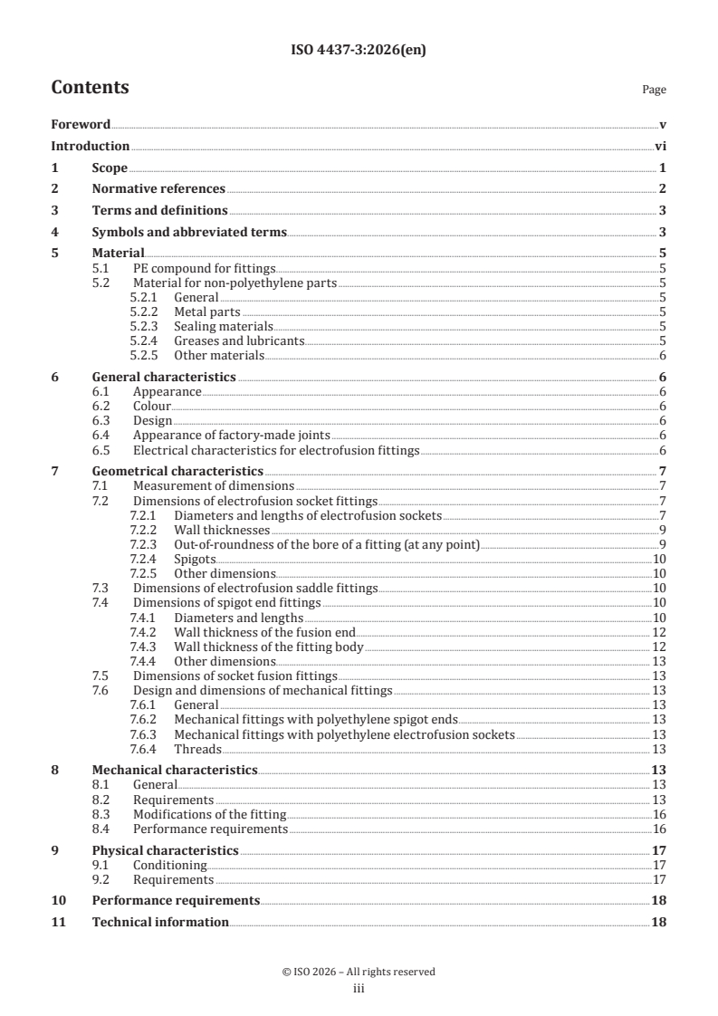
Contents Page
Foreword .v
Introduction .vi
1 Scope . 1
2 Normative references . 2
3 Terms and definitions . 3
4 Symbols and abbreviated terms. 3
5 Material. 5
5.1 PE compound for fittings .5
5.2 Material for non-polyethylene parts .5
5.2.1 General .5
5.2.2 Metal parts .5
5.2.3 Sealing materials .5
5.2.4 Greases and lubricants .5
5.2.5 Other materials .6
6 General characteristics . 6
6.1 Appearance .6
6.2 Colour .6
6.3 Design .6
6.4 Appearance of factory-made joints .6
6.5 Electrical characteristics for electrofusion fittings .6
7 Geometrical characteristics . 7
7.1 Measurement of dimensions .7
7.2 Dimensions of electrofusion socket fittings .7
7.2.1 Diameters and lengths of electrofusion sockets .7
7.2.2 Wall thicknesses .9
7.2.3 Out-of-roundness of the bore of a fitting (at any point) .9
7.2.4 Spigots.10
7.2.5 Other dimensions.10
7.3 Dimensions of electrofusion saddle fittings .10
7.4 Dimensions of spigot end fittings .10
7.4.1 Diameters and lengths .10
7.4.2 Wall thickness of the fusion end . 12
7.4.3 Wall thickness of the fitting body . 12
7.4.4 Other dimensions. 13
7.5 Dimensions of socket fusion fittings . 13
7.6 Design and dimensions of mechanical fittings . 13
7.6.1 General . 13
7.6.2 Mechanical fittings with polyethylene spigot ends . 13
7.6.3 Mechanical fittings with polyethylene electrofusion sockets . 13
7.6.4 Threads . 13
8 Mechanical characteristics .13
8.1 General . 13
8.2 Requirements . 13
8.3 Modifications of the fitting .16
8.4 Performance requirements .16
9 Physical characteristics . 17
9.1 Conditioning.17
9.2 Requirements .17
10 Performance requirements . .18
11 Technical information.18
iii
12 Marking . . 19
12.1 General .19
12.2 Minimum required marking of fittings .19
12.3 Additional marking. 20
12.4 Fusion system recognition . 20
13 Delivery conditions .20
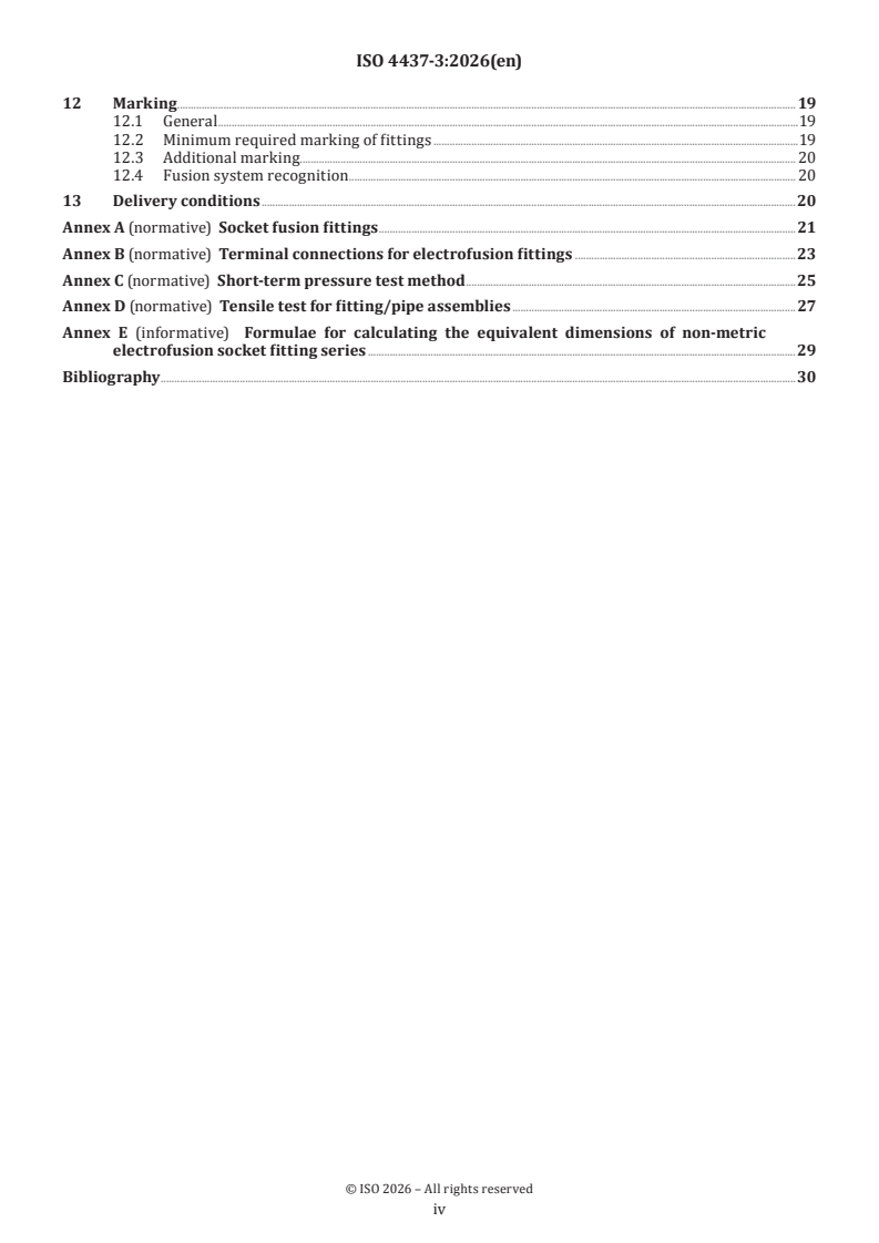
Annex A (normative) Socket fusion fittings .21
Annex B (normative) Terminal connections for electrofusion fittings .23
Annex C (normative) Short-term pressure test method .25
Annex D (normative) Tensile test for fitting/pipe assemblies .27
Annex E (informative) Formulae for calculating the equivalent dimensions of non-metric
electrofusion socket fitting series .29
Bibliography .30
iv
Foreword
ISO (the International Organization for Standardization) is a worldwide federation of national standards
bodies (ISO member bodies). The work of preparing International Standards is normally carried out through
ISO technical committees. Each member body interested in a subject for which a technical committee
has been established has the right to be represented on that committee. International organizations,
governmental and non-governmental, in liaison with ISO, also take part in the work. ISO collaborates closely
with the International Electrotechnical Commission (IEC) on all matters of electrotechnical standardization.
The procedures used to develop this document and those intended for its further maintenance are described
in the ISO/IEC Directives, Part 1. In particular, the different approval criteria needed for the different types
of ISO document should be noted. This document was drafted in accordance with the editorial rules of the
ISO/IEC Directives, Part 2 (see www.iso.org/directives).
ISO draws attention to the possibility that the implementation of this document may involve the use of (a)
patent(s). ISO takes no position concerning the evidence, validity or applicability of any claimed patent
rights in respect thereof. As of the date of publication of this document, ISO had not received notice of (a)
patent(s) which may be required to implement this document. However, implementers are cautioned that
this may not represent the latest information, which may be obtained from the patent database available at
www.iso.org/patents. ISO shall not be held responsible for identifying any or all such patent rights.
Any trade name used in this document is information given for the convenience of users and does not
constitute an endorsement.
For an explanation of the voluntary nature of standards, the meaning of ISO specific terms and expressions
related to conformity assessment, as well as information about ISO's adherence to the World Trade
Organization (WTO) principles in the Technical Barriers to Trade (TBT), see www.iso.org/iso/foreword.html.
This document was prepared by Technical Committee ISO/TC 138, Plastics pipes, fittings and valves for the
transport of fluids, Subcommittee SC 4, Plastics pipes and fittings for the supply of gaseous fuels.
This third edition cancels and replaces the second edition (ISO 4437-3:2024), which has been technically
revised.
The main changes are as follows:
— reference to information related to the suitability of PE pipe systems for 100 % hydrogen and its
admixtures with natural gas has been made;
— terms and definitions have been distributed over ISO 4437-1, ISO 4437-2 and ISO 4437-3;
— symbols and their definitions for geometrical characteristics on electrofusion socket fittings, spigot
end fittings, socket fusion fittings and tapping tees have been harmonized with other standards in
ISO/TC 138;
— Clause 5 has been restructured;
— the minimum bore for electrofusion socket fittings have been harmonized with the minimum bore of
spigot end fittings;
— the performance requirements for joints have been mentioned more explicitly by adding Table 8.
A list of all parts in the ISO 4437 series can be found on the ISO website.
Any feedback or questions on this document should be directed to the user’s national standards body. A
complete listing of these bodies can be found at www.iso.org/members.html.
v
Introduction
The ISO 4437 series specifies the requirements for a piping system and its components made from
polyethylene (PE) compounds, which is intended to be used for the supply of gaseous fuels.
This document covers the characteristics of fittings.
Requirements and test methods for materials and components, other than fittings, are specified in
ISO 4437-1, ISO 4437-2 and ISO 4437-4.
Characteristics for fitness for purpose of the system are covered in ISO 4437-5. ISO/TS 4437-7 gives guidance
for assessment of conformity.
Recommended practice for design, handling and installation is given in ISO/TS 10839.
vi
International Standard ISO 4437-3:2026(en)
Plastics piping systems for the supply of gaseous fuels —
Polyethylene (PE) —
Part 3:
Fittings
1 Scope
This document specifies the characteristics of fusion fittings made from polyethylene (PE) as well as of
mechanical fittings for piping systems in the field of the supply of gaseous fuels.
NOTE 1 Additional information related to the installation of PE 100-RC systems is given in ISO 4437-1:2026,
Annex A.
NOTE 2 Additional information about the suitability of PE pipe systems for hydrogen and its admixtures is given in
ISO 4437-1:2026, Annex D.
It also specifies the test parameters for the test methods referred to in this document.
In conjunction with ISO 4437-1, ISO 4437-2, ISO 4437-4 and ISO 4437-5, this document is applicable to PE
pipes, fittings and valves, their joints, and joints with components of PE and other materials intended to be
used under the following conditions:
1)
a) a maximum operating pressure (MOP) up to and including 10 bar , at a design reference temperature of
20 °C;
b) an operating temperature between −20 °C and 40 °C.
For operating temperatures between 20 °C and 40 °C, derating coefficients are specified in ISO 4437-5.
The ISO 4437 series covers a range of MOPs and gives requirements concerning colours.
This document is applicable for fittings of the following types:
— electrofusion socket fittings;
— electrofusion saddle fittings;
— spigot end fittings (for butt fusion using heated tools and electrofusion);
— socket fusion fittings;
— mechanical fittings.
It is the responsibility of the purchaser or specifier to make the appropriate selections from these aspects,
taking into account their particular requirements and any relevant national guidance or regulations and
installation practices or codes.
NOTE 3 The fittings can be, for example, in the form of couplers, saddles, equal and reduced tees, reducers, elbows,
bends or end caps.
NOTE 4 Fabricated fittings are normally not used for gas applications except for larger dimensions or in the absence
of other solutions. Guidance can be found in ISO 4427-3:2019, Annex B.
5 2
1) 1 bar = 0,1 MPa = 10 Pa; 1 MPa = 1 N/mm .
2 Normative references
The following documents are referred to in the text in such a way that some or all of their content constitutes
requirements of this document. For dated references, only the edition cited applies. For undated references,
the latest edition of the referenced document (including any amendments) applies.
ISO 7-1, Pipe threads where pressure-tight joints are made on the threads — Part 1: Dimensions, tolerances and
designation
ISO 228-1, Pipe threads where pressure-tight joints are not made on the threads — Part 1: Dimensions, tolerances
and designation
ISO 1133-1, Plastics — Determination of the melt mass-flow rate (MFR) and melt volume-flow rate (MVR) of
thermoplastics — Part 1: Standard method
ISO 1167-1:2006, Thermoplastics pipes, fittings and assemblies for the conveyance of fluids — Determination of
the resistance to internal pressure — Part 1: General method
ISO 1167-4, Thermoplastics pipes, fittings and assemblies for the conveyance of fluids — Determination of the
resistance to internal pressure — Part 4: Preparation of assemblies
ISO 3126, Plastics piping systems — Plastics components — Determination of dimensions
ISO 4437-1:2026, Plastics piping systems for the supply of gaseous fuels — Polyethylene (PE) — Part 1: General
ISO 4437-2:2026, Plastics piping systems for the supply of gaseous fuels — Polyethylene (PE) — Part 2: Pipes
ISO 4437-5, Plastics piping systems for the supply of gaseous fuels — Polyethylene (PE) — Part 5: Fitness for
purpose of the system
ISO 11357-6, Plastics — Differential scanning calorimetry (DSC) — Part 6: Determination of oxidation induction
time (isothermal OIT) and oxidation induction temperature (dynamic OIT)
ISO 12176-5, Plastics pipes and fittings — Equipment for fusion jointing polyethylene systems — Part 5: Two-
dimensional data coding of components and data exchange format for PE piping systems
ISO 13950, Plastics pipes and fittings — Automatic recognition systems for electrofusion joints
ISO 13951, Plastics piping systems — Test method for the resistance of plastic pipe/pipe or pipe/fitting
assemblies to tensile loading
ISO 13953, Polyethylene (PE) pipes and fittings — Determination of the tensile strength and failure mode of test
pieces from a butt-fused joint
ISO 13954, Plastics pipes and fittings — Peel decohesion test for polyethylene (PE) electrofusion assemblies of
nominal outside diameter greater than or equal to 90 mm
ISO 13955, Plastics pipes and fittings — Crushing decohesion test for polyethylene (PE) electrofusion assemblies
ISO 13956, Plastics pipes and fittings — Decohesion test of polyethylene (PE) saddle fusion joints — Evaluation
of ductility of fusion joint interface by tear test
ISO 13957, Plastics pipes and fittings — Polyethylene (PE) tapping tees — Test method for impact resistance
ISO 16010, Elastomeric seals — Material requirements for seals used in pipes and fittings carrying gaseous fuels
and hydrocarbon fluids
ISO 17778, Plastics piping systems — Fittings, valves and ancillaries — Determination of gaseous flow rate/
pressure drop relationships
ISO 17885:2021, Plastics piping systems — Mechanical fittings for pressure piping systems — Specifications
ISO 18488, Polyethylene (PE) materials for piping systems — Determination of strain hardening modulus in
relation to slow crack growth — Test method
3 Terms and definitions
For the purposes of this document, the terms and definitions given in ISO 4437-1, ISO 4437-2 and the
following apply.
ISO and IEC maintain terminology databases for use in standardization at the following addresses:
— ISO Online browsing platform: available at https:// www .iso .org/ obp
— IEC Electropedia: available at https:// www .electropedia .org/
3.1
electrofusion socket fitting
fitting which contains one or more integrated heating elements that are capable of transforming electrical
energy into heat to realize a fusion joint with a spigot end or a pipe
3.2
electrofusion saddle fitting
fitting which contains one or more integrated heating elements that are capable of transforming electrical
energy into heat to realize a fusion joint onto a pipe
3.2.1
tapping tee
electrofusion saddle fitting (3.2) (top loading or wrap round) that contains a cutter to tap through the wall of
the main pipe and remains in the body of this fitting
3.2.2
branch saddle
electrofusion saddle fitting (3.2) (top loading or wrap round) that requires an ancillary cutting tool for
drilling a hole in the adjoining main pipe
3.3
spigot end fitting
fitting where the outside diameter of the spigot end is equal to the nominal outside diameter, d , of the
n
corresponding pipe
3.4
socket fusion fitting
fitting designed to accept the insertion of a pipe or spigot end to realize a fusion joint between mating
surfaces using the socket fusion process
3.5
mechanical fitting
fitting for assembling plastics pipes with each other or with a metal pipe or fitting, that includes one or more
compression zones to provide pressure integrity, leak tightness and resistance to end loads
[SOURCE: ISO 17885:2021, 3.1.1]
4 Symbols and abbreviated terms
For the purposes of this document, the symbols and abbreviated terms given in ISO 4437-1, ISO 4437-2 and
the following apply.
A percentage of decohesion (area)
d
c outside diameter of the terminal shroud
c diameter of the contact area of the terminal
c internal diameter of the terminal shroud
c maximum overall diameter of the base of the contact area
D mean outside diameter of the fusion end piece
D mean inside diameter in the fusion zone measured in a plane parallel to the plane of the mouth at a
distance of L + 0,5L from that face
3 2
D bore, i.e. the minimum diameter of the flow channel through the plastic body of the fitting
D mean inside mouth diameter of the socket, i.e. the mean diameter of the circle at the intersection of
the extension of the socket with the plane of the socket mouth
D mean inside root diameter of the socket, i.e. the mean diameter of the circle in a plane parallel to the
plane of the mouth and separated from it by a distance of L which is the reference length of the socket
E fusion face wall thickness
E wall thickness (at any point) of the fitting body
h internal depth of the terminal shroud
h distance between the upper part of the terminal shroud and the contact area
h height of the contact area
H height of the saddle, i.e. the distance from the top of the main pipe to the top of the tapping tee or saddle
H height of the service pipe, i.e. the distance from the top of the main pipe to the axis of the service pipe
L depth of penetration of the pipe or spigot end fitting
L heated length within the socket, i.e. the nominal length of the fusion zone as declared by the man-
ufacturer
L distance between the mouth of the fitting and the start of the fusion zone, i.e. the nominal unheated
entrance length of the fitting as declared by the manufacturer
L cut-back length of the fusion end piece
L tubular length of the fusion end piece
L socket length, i.e. the length from mouth to shoulder, if any
L insertion depth, i.e. the depth of the heated pipe end into the socket
L heated socket length, i.e. the length of penetration of the heated tool into the socket
L reference socket length, i.e. the theoretical minimum socket length used for the purpose of calculation
L heated pipe length, i.e. the depth of penetration of the pipe end into the heated tool
L percentage of decohesion (length)
d
W width of the tapping tee, i.e. the distance between the axis of the main pipe and the plane of the
mouth of the service tee
5 Material
5.1 PE compound for fittings
The stress-bearing PE parts of injection moulded fittings or compression moulded plates, for example the
main body of the fitting, shall only be made from virgin material conforming to ISO 4437-1. The stress-
bearing PE parts of fittings made from pipe shall be made from pipe conforming to ISO 4437-2, except for the
geometrical characteristics.
Other PE materials may be used for non-stress-bearing parts, e.g. clamps for electrofusion saddle fittings
that only maintain a function during installation.
A fitting can only be designated as a PE 100-RC fitting if:
— the stress bearing part is produced from PE 100-RC materials which fulfil the requirements of
ISO 4437-1:2026, Tables 1 and 2, and are declared as PE 100-RC by the raw material producer;
— it fulfils the requirements of Table 4 of this document for PE 100-RC.
5.2 Material for non-polyethylene parts
5.2.1 General
All components shall conform to the relevant International Standards. Alternative standards may be applied
in cases where suitable International Standards do not exist.
The materials and the constituent elements used in making the fitting (including elastomers and any metal
parts used) shall be as resistant to the external and internal environments as the other elements of the
piping system.
Other materials used in fittings in contact with the PE pipe shall not adversely affect pipe performance or
initiate stress cracking.
In all cases, fitness for purpose of the system of the components shall be demonstrated.
5.2.2 Metal parts
All metal parts susceptible to corrosion shall be adequately protected, providing this is necessary for the
durability and function of the system.
When dissimilar metallic materials are used, galvanic corrosion shall be avoided.
5.2.3 Sealing materials
Elastomeric seals shall conform to ISO 16010.
Other sealing materials are permitted if proven suitable for gas supply systems.
5.2.4 Greases and lubricants
Greases or lubricants shall not exude onto fusion areas and shall not affect the long-term performance of
fitting materials.
5.2.5 Other materials
Other materials as stress bearing part of the fitting shall have an expected lifetime at least equal to that
of the PE pipes conforming to ISO 4437-2 with which they are intended to be used under the following
conditions:
a) during storage;
b) under the effect of gaseous fuels conveyed therein (see ISO 4437-1);
c) with respect to the service environment, e.g. for corrosion, mechanical resistance and material
degradation;
d) during operation.
Non-stress-bearing fitting parts, e.g. clamps for electrofusion saddle fittings that only maintain a function
during installation, may be made from other materials.
6 General characteristics
6.1 Appearance
When viewed without magnification, the internal and external surfaces of fittings shall be clean, and
shall have no scoring, cavities or other surface defects to an extent that would prevent conformity to this
document.
No component of the fitting shall show any signs of damage, scratches, pitting, bubbles, blisters, inclusions
or cracks to an extent that would prevent conformity of the fittings to the requirements of this document.
6.2 Colour
The colour of the PE parts of the fitting shall be either black, yellow or orange in accordance with ISO 4437-1.
6.3 Design
The design of the fitting shall be such that, when assembling the fitting onto the pipe or other component,
electrical coils and/or seals are not displaced.
Tapping tees may be provided with upper and lower end stops for the tapping cutter, or other means of
indicating the cutter position according to the manufacturer’s instructions.
Tapping tees may be provided with a means to prevent uncontrolled gas release during tapping.
6.4 Appearance of factory-made joints
The internal and external surfaces of the pipe and fitting after fusion jointing, examined visually without
magnification, shall be free from melt that has flowed outside the confines of the fitting, apart from that
which may be declared acceptable by the fitting manufacturer or used deliberately as a fusion marker.
There shall be no excessive creasing of the internal surfaces of the adjoining components.
6.5 Electrical characteristics for electrofusion fittings
The electrical protection that shall be provided by the fusion process depends on the voltage and the current
used and on the characteristics of the electricity power source.
For voltages greater than 25 V, direct human contact with energized parts shall not be possible when the
fitting is in the fusion cycle during assembly in accordance with the instructions of the manufacturers of the
fittings and of the assembly equipment, as applicable.
NOTE 1 Electrofusion fittings are part of an electrical circuit when connected to the control units. Definitions of
electrical circuits and applicable protections are found in the relevant IEC standards.
The tolerance on the electrical resistance of the fitting at 23 °C shall be stated by the manufacturer. The
resistance shall be between nominal resistance (−10 %) and nominal resistance [(+10 %) + 0,1 Ω].
NOTE 2 0,1 Ω is the assumed value of the contact resistance.
The surface finish of the terminal pins shall allow a minimum contact resistance in order to satisfy the
resistance tolerance requirements.
Annex B specifies electrofusion terminal connections.
7 Geometrical characteristics
7.1 Measurement of dimensions
The dimensions of the fitting shall be measured in accordance with ISO 3126 and rounded to the next greater
0,1 mm. In case of dispute, the measurement shall be made at least 24 h after manufacture and after being
conditioned for at least 4 h at (23 ± 2) °C.
Additionally, for spigot end fittings provided with temporary supports, dimensional measurement shall be
performed at least 1 h after removal of the supports.
Indirect measurement at the stage of production is allowed at shorter time periods, provided that evidence
is shown of correlation.
7.2 Dimensions of electrofusion socket fittings
7.2.1 Diameters and lengths of electrofusion sockets
For electrofusion sockets (see Figure 1) having a nominal diameter as given in Table 1, the socket diameter
and lengths shall be given by the manufacturer and shall conform to Table 1 with the following condition:
L ≥ 5 mm.
The value of L is not greater than half the total length of the fitting in case of coupling without stop.
Key
D mean inside diameter in the fusion zone measured in a plane parallel to the plane of the mouth at a distance
of L + 0,5L from that face
3 2
D bore, i.e. the minimum diameter of the flow channel through the plastic body of the fitting
L depth of penetration of the pipe or spigot end fitting
L heated length within the socket, i.e. the nominal length of the fusion zone as declared by the manufacturer
L distance between the mouth of the fitting and the start of the fusion zone, i.e. the nominal unheated entrance
length of the fitting as declared by the manufacturer
Figure 1 — Dimensions of electrofusion socket fittings
Table 1 — Dimensions of electrofusion socket fittings
Dimensions in millimetres
b
Nominal Bore Depth of penetration Fusion zone
diameter
d D L L
n 2 1 2
a
min. min. max. min.
16 9 25 41 10
20 13 25 41 10
25 18 25 41 10
32 25 25 44 10
40 31 25 49 10
50 39 28 55 10
63 49 31 63 11
75 59 35 70 12
90 71 40 79 13
110 87 53 82 15
125 99 58 87 16
140 111 62 92 18
160 127 68 98 20
180 143 74 105 21
200 159 80 112 23
225 179 88 120 26
250 199 95 129 33
a
An extended L value may be agreed between the end user and the manufacturer. In
this case, compatibility of such fittings is not given with components with a minimum
tubular length of spigots L according to Table 3.
b
The requirement on D is only applicable for SDR 11 or higher.
TTabablele 1 1 ((ccoonnttiinnueuedd))
b
Nominal Bore Depth of penetration Fusion zone
diameter
d D L L
n 2 1 2
a
min. min. max. min.
280 223 104 139 35
315 251 115 150 39
355 283 127 164 42
400 319 140 179 47
450 359 155 195 51
500 399 170 212 56
560 447 188 235 61
630 503 209 255 67
710 567 220 280 74
800 639 230 300 82
a
An extended L value may be agreed between the end user and the manufacturer. In
this case, compatibility of such fittings is not given with components with a minimum
tubular length of spigots L according to Table 3.
b
The requirement on D is only applicable for SDR 11 or higher.
The mean inside diameter of the fitting in the middle of the fusion zone (see D in Figure 1) shall not be less
than d .
n
In the case of a fitting having sockets of differing nominal diameters, each one shall conform to the
requirements for the nominal diameter of the corresponding component.
Information for non-metric series is given in Annex E.
7.2.2 Wall thicknesses
In order to prevent stress concentrations, any changes in wall thickness of the fitting body shall be gradual.
a) The wall thickness at any point of the fitting body, E , shall be greater than or equal to e for the
1 min
corresponding pipe at any part of the fitting located at a distance beyond a maximum of 2/3 L from all
entrance faces, if the fitting and the corresponding pipe are made from a polyethylene having the same
MRS.
If the fitting is produced from a polyethylene having an MRS that is different from that of the
corresponding pipe, the relation between the wall thickness of the fitting, E , and the pipe, e , shall be
1 min
in accordance with Table 2.
b) In the case of a wall thickness design different from that according to a), fittings and associated fusion
joints shall additionally meet the performance requirements given in 8.4.
Table 2 — Relation between fitting wall thickness,E, and pipe wall thickness,e
1 min
Pipe and fitting material
Relationship
Pipe Fitting
PE 80 PE 100 or PE 100-RC E ≥ 0,8 e
1 min
PE 100 or PE 100-RC PE 80 E ≥ 1,25 e
1 min
7.2.3 Out-of-roundness of the bore of a fitting (at any point)
When a fitting leaves the site of the manufacturer, the out-of-roundness of the bore of a fitting at any point
shall not exceed 0,015 d .
n
7.2.4 Spigots
For fittings that contain spigot outlets (e.g. electrofusion equal tee with a spigot branch), the dimensions of
the spigot shall conform to 7.4.
For technical and design reasons, the shape of the minimum bore cross-section area can be different from
that of spigot fittings as given in 7.4.
7.2.5 Other dimensions
The dimensional characteristics appropriate to each manufacturer, such as the overall dimensions or
mounting dimensions, shall be specified in a technical file.
In the case of a coupling without an internal stop or with a removable centre register, the geometry of the
fitting shall allow the penetration of the pipe through the fitting.
7.3 Dimensions of electrofusion saddle fittings
Outlets from tapping tees and branch saddles shall have spigots in accordance with 7.4 or an electrofusion
socket in accordance with 7.2. The manufacturer shall specify the overall dimensions of the fitting in a
technical file. These dimensions shall include the main pipe and outlet dimensions, maximum height of the
saddle, H, and for tapping tees the height of the service pipe, H (see Figure 2).
For technical and design reasons, the minimum bore diameter, D , may be different from that of spigot
fittings as given in 7.4.
Key
H height of the saddle, i.e. the distance from the top of the main pipe to the top of the tapping tee or saddle
H height of service pipe, i.e. the distance from the top of the main pipe to the axis of the service pipe
W width of the tapping tee, i.e. the distance between the axis of the main pipe and the plane of the mouth of the
service tee
Figure 2 — Dimensions of tapping tees (electrofusion saddle fittings)
7.4 Dimensions of spigot end fittings
7.4.1 Diameters and lengths
The dimensions of spigot end fittings (see Figure 3) shall conform to the values given in Table 3.
The mean outside diameter of the fusion end piece (D) is measured in any plane parallel to the plane of the
mouth and at a distance not greater than the tubular length of the fusion end piece (L ) from that plane.
The measurement of the bore (D ) does not include the fusion bead (if present).
The fusion face wall thickness (E) is measured at any point at a maximum distance of L (cut-back length of
the fusion end piece) from the entrance face and shall be equal to the pipe wall thickness and tolerance to
which it is intended to be butt-fused, as specified in ISO 4437-2. E is at least 3 mm.
The cut-back length of the fusion end piece (L ) comprises the initial depth of the spigot end necessary for
butt fusion or reweld and can be obtained by joining a length of pipe to the spigot end of the fitting, provided
that the wall thickness of the pipe is equal to E for its entire length.
The tubular length of the fusion end piece (L ) comprises the initial length of the fusion end piece and shall
allow the following (in any combination):
— the use of clamps required in the case of butt fusion,
— assembly with an electrofusion fitting,
— the use of a mechanical scraper.
Key
D mean outside diameter of the fusion end piece
D bore, i.e. the minimum diameter of the flow channel through the plastic body of the fitting
E fusion face wall thickness
E wall thickness (at any point) of the fitting body
L cut-back length of the fusion end piece
L tubular length of the fusion end piece
Figure 3 — Dimensions of spigot end fittings
Table 3 — Dimensions of spigot end fittings
Dimensions in millimetres
b c
Nominal Mean outside diam- Bore For electrofusion and butt fusion For socket For butt fusion only
diameter eter of the fusion fusion
end piece
Out-of- Cut-back Tubular Tubular Out-of- Cut-back Tubular
d
roundness length length length roundness length length
d D D L L L L L
n 2 4 5 5 4 5
a
min. max. min. max. min. min. min. max. min. min.
16 16,0 16,3 9 0,3 25 41 10 — — —
20 20,0 20,3 13 0,3 25 41 11 — — —
25 25,0 25,3 18 0,4 25 41 12,5 — — —
32 32,0 32,3 25 0,5 25 44 14,6 — — —
40 40,0 40,4 31 0,6 25 49 17 — — —
a
In accordance with ISO 11922-1:2018, Grade B except for d 40 and 50.
n
b
The requirement on D are only applicable for SDR 11 or higher. Other minimum bores have to be agreed between manufacturer and end user.
c
Spigot fittings designed for electrofusion are also suitable for butt fusion.
d
Spigot end fittings may have a shorter tubular length L for factory assemblies or in association with appropriate electrofusion fittings.
TTabablele 3 3 ((ccoonnttiinnueuedd))
b c
Nominal Mean outside diam- Bore For electrofusion and butt fusion For socket For butt fusion only
diameter eter of the fusion fusion
end piece
Out-of- Cut-back Tubular Tubular Out-of- Cut-back Tubular
d
roundness length length length roundness length length
d D D L L L L L
n 2 4 5 5 4 5
a
min. max. min. max. min. min. min. max. min. min.
50 50,0 50,4 39 0,8 25 55 20 — — —
63 63,0 63,4 49 0,9 25 63 24 1,5 5 16
75 75,0 75,5 59 1,2 25 70 25 1,6 6 19
90 90,0 90,6 71 1,4 28 79 28 1,8 6 22
110 110,0 110,7 87 1,7 32 82 32 2,2 8 28
125 125,0 125,8 99 1,9 35 87 35 2,5 8 32
140 140,0 140,9 111 2,1 38 92 — 2,8 8 35
160 160,0 161,0 127 2,4 42 98 — 3,2 8 40
180 180,0 181,1 143 2,7 46 105 — 3,6 8 45
200 200,0 201,2 159 3,0 50 112 — 4,0 8 50
225 225,0 226,4 179 3,4 55 120 — 4,5 10 55
250 25
...