

ISO 22090-1
(Main)Ships and marine technology — Transmitting heading devices (THDs) — Part 1: Gyro-compasses
General Information
- Abstract
This part of ISO 22090 specifies the construction, performance, and testing of gyro-compasses as transmitting heading device required by chapter V, SOLAS 1974 (as amended). A Transmitting heading device (THD) is an electronic device that provides information about the ship’s true heading. In addition to the general requirements contained in IMO Resolution A.694(17) to which IEC 60945 is associated and the relevant standard for the sensing part used, the THD equipment shall comply with the following minimum requirements. Where the IMO performance standards that apply to the sensing part do not specify a geographical operating area that the THD shall operate a) at maximum rate of turn 20 °/s and b) from 70° latitude south to 70° latitude north as minimum. The THDs complying with the requirements contained in this part of ISO 22090 can be used for heading information as contained in chapter V of the SOLAS Convention. However, ships within a speed range of 30 kn to 70 kn should comply with the requirements of IMO Resolution A.821(19). In addition, such THD should meet the dynamic requirements contained in the HSC Code, chapter 13 for the carriage of a suitable device providing heading information. NOTE 1 Several technologies can be used to detect and transmit heading information. It is illogical to standardize the detection of the heading separately from the transmission of the heading. Therefore, separate parts of this part of ISO 22090 refer to different technologies. The requirements of this part of ISO 22090 only apply to gyroscopic technology. Other technologies are covered in other parts of ISO 22090. NOTE 2 All requirements that are extracted from the recommendations of IMO Resolution MSC. 116(73) on performance standards for transmitting heading devices are printed in italics. The main changes compared to the present edition are as follows; — Requirements related to bridge alert management (BAM) will be added to the clause of requirements and type test. — IEC 61162-450 will be added to the clause of interface as an option. — The normative references and bibliography will be updated. — Editorial revision of the standard in general according to the ISO/IEC Directives, Part 2 — Additionally, Annex will be added as alert definitions and IEC 61162 interface overviews for further explanation of the above.
- Status
- Not Published
- Technical Committee
- ISO/TC 8/SC 6 - Navigation and ship operations
- Drafting Committee
- ISO/TC 8/SC 6 - Navigation and ship operations
- Current Stage
- 6000 - International Standard under publication
- Start Date
- 19-Sep-2026
- Completion Date
- 26-Sep-2026
Buy Documents
ISO/FDIS 22090-1 - Ships and marine technology — Transmitting heading devices (THDs) — Part 1: Gyro-compasses
REDLINE ISO/FDIS 22090-1 - Ships and marine technology — Transmitting heading devices (THDs) — Part 1: Gyro-compasses
Overview
ISO 22090-1:2026 – Ships and marine technology – Transmitting Heading Devices (THDs) – Part 1: Gyro-compasses establishes the requirements for the construction, performance, and testing of gyro-compass-based transmitting heading devices (THDs) for marine navigation. Developed by the International Organization for Standardization (ISO), this standard ensures compliance with IMO (International Maritime Organization) conventions, particularly SOLAS 1974, Chapter V, for the safety of life at sea. ISO 22090-1 focuses specifically on THDs using gyroscopic technology, outlining operational guidelines and testing protocols for accurate and reliable heading information transmission on ships worldwide.
Key Topics
- Transmitting Heading Device (THD): Electronic equipment that delivers precise true heading information, essential for safe navigation.
- Gyro-compass Technology: Part 1 applies only to gyro-compasses, which are robust and stable heading sensors using gyroscopic principles.
- Performance Standards: Aligns with IMO Resolution MSC.116(73), covering accuracy, operational latitude (70°N to 70°S), and dynamic performance.
- Construction and Testing: Specifies requirements and test procedures for construction quality and performance, including static and dynamic accuracy, error correction, and continuous operation.
- Interface and Compatibility: Mandates compliance with international marine interface standards such as IEC 61162-1, IEC 61162-2, and optionally IEC 61162-450, ensuring THDs can interface with other navigational systems.
- Alert and Status Management: Incorporates modern bridge alert management (BAM) as per IEC 62923 and IMO MSC.302(87), including alerts for system malfunctions and power failures.
- Environmental and EMC Requirements: Devices must maintain performance under marine environmental conditions-vibration, humidity, temperature variations-and adhere to electromagnetic compatibility standards.
Applications
ISO 22090-1 is vital for ship designers, equipment manufacturers, system integrators, and maritime operators who require robust, accurate, and IMO-compliant heading information. The standard is primarily used for:
- New Ship Builds and Refits: Ensuring integrated navigation systems meet global carriage requirements and work seamlessly with other bridge equipment.
- Gyro-compass Manufacturers: Providing design and testing criteria for developing THDs that deliver reliable heading data in all operational environments.
- Regulatory Compliance: Supporting flag states and classification societies in verifying that installed THDs meet SOLAS Chapter V and relevant IMO resolutions.
- High-Speed Craft: Clarifies that vessels operating between 30 and 70 knots should additionally comply with IMO Resolution A.821(19) and the HSC Code.
- Bridge Alert Integration: Facilitates integration of heading devices with BAM for harmonized alert presentation, crucial for modern bridge operations and safety management.
Related Standards
Implementers of ISO 22090-1 often reference additional international standards and IMO resolutions, including:
- IEC 60945: General requirements for marine navigation equipment regarding testing and results.
- IEC 61162 Series (IEC 61162-1, -2, -450): Specifications for digital interfaces between marine navigation and communication equipment.
- IEC 62288: Requirements for the presentation of information on navigational displays.
- IEC 62923-1 and -2: Requirements for bridge alert management, including operational/test methods and alert identifiers.
- IMO Resolution MSC.116(73): Performance standards for THDs.
- IMO Resolution A.694(17): General requirements for shipborne radio and electronic navigational aids.
- IMO Resolution A.424(XI) & A.813(19): Performance and electromagnetic compatibility standards for gyro-compasses.
- SOLAS Chapter V: Requirements for shipborne navigational equipment.
- HSC Code, Chapter 13: Requirements for heading devices on high-speed craft.
ISO 22090-1:2026 ensures that gyro-compass-based transmitting heading devices deliver dependable and internationally accepted heading information for safe marine navigation, supporting the global shipping industry’s compliance, interoperability, and operational efficiency.
Relations
- Effective Date
- 06-Jun-2022
Buy Documents
ISO/FDIS 22090-1 - Ships and marine technology — Transmitting heading devices (THDs) — Part 1: Gyro-compasses
REDLINE ISO/FDIS 22090-1 - Ships and marine technology — Transmitting heading devices (THDs) — Part 1: Gyro-compasses
Get Certified
Connect with accredited certification bodies for this standard

DNV
DNV is an independent assurance and risk management provider.

Lloyd's Register
Lloyd's Register is a global professional services organisation specialising in engineering and technology.

FSC International
Forest Stewardship Council certification.
Sponsored listings
Frequently Asked Questions
ISO 22090-1 is a draft published by the International Organization for Standardization (ISO). Its full title is "Ships and marine technology — Transmitting heading devices (THDs) — Part 1: Gyro-compasses". This standard covers: This part of ISO 22090 specifies the construction, performance, and testing of gyro-compasses as transmitting heading device required by chapter V, SOLAS 1974 (as amended). A Transmitting heading device (THD) is an electronic device that provides information about the ship’s true heading. In addition to the general requirements contained in IMO Resolution A.694(17) to which IEC 60945 is associated and the relevant standard for the sensing part used, the THD equipment shall comply with the following minimum requirements. Where the IMO performance standards that apply to the sensing part do not specify a geographical operating area that the THD shall operate a) at maximum rate of turn 20 °/s and b) from 70° latitude south to 70° latitude north as minimum. The THDs complying with the requirements contained in this part of ISO 22090 can be used for heading information as contained in chapter V of the SOLAS Convention. However, ships within a speed range of 30 kn to 70 kn should comply with the requirements of IMO Resolution A.821(19). In addition, such THD should meet the dynamic requirements contained in the HSC Code, chapter 13 for the carriage of a suitable device providing heading information. NOTE 1 Several technologies can be used to detect and transmit heading information. It is illogical to standardize the detection of the heading separately from the transmission of the heading. Therefore, separate parts of this part of ISO 22090 refer to different technologies. The requirements of this part of ISO 22090 only apply to gyroscopic technology. Other technologies are covered in other parts of ISO 22090. NOTE 2 All requirements that are extracted from the recommendations of IMO Resolution MSC. 116(73) on performance standards for transmitting heading devices are printed in italics. The main changes compared to the present edition are as follows; — Requirements related to bridge alert management (BAM) will be added to the clause of requirements and type test. — IEC 61162-450 will be added to the clause of interface as an option. — The normative references and bibliography will be updated. — Editorial revision of the standard in general according to the ISO/IEC Directives, Part 2 — Additionally, Annex will be added as alert definitions and IEC 61162 interface overviews for further explanation of the above.
This part of ISO 22090 specifies the construction, performance, and testing of gyro-compasses as transmitting heading device required by chapter V, SOLAS 1974 (as amended). A Transmitting heading device (THD) is an electronic device that provides information about the ship’s true heading. In addition to the general requirements contained in IMO Resolution A.694(17) to which IEC 60945 is associated and the relevant standard for the sensing part used, the THD equipment shall comply with the following minimum requirements. Where the IMO performance standards that apply to the sensing part do not specify a geographical operating area that the THD shall operate a) at maximum rate of turn 20 °/s and b) from 70° latitude south to 70° latitude north as minimum. The THDs complying with the requirements contained in this part of ISO 22090 can be used for heading information as contained in chapter V of the SOLAS Convention. However, ships within a speed range of 30 kn to 70 kn should comply with the requirements of IMO Resolution A.821(19). In addition, such THD should meet the dynamic requirements contained in the HSC Code, chapter 13 for the carriage of a suitable device providing heading information. NOTE 1 Several technologies can be used to detect and transmit heading information. It is illogical to standardize the detection of the heading separately from the transmission of the heading. Therefore, separate parts of this part of ISO 22090 refer to different technologies. The requirements of this part of ISO 22090 only apply to gyroscopic technology. Other technologies are covered in other parts of ISO 22090. NOTE 2 All requirements that are extracted from the recommendations of IMO Resolution MSC. 116(73) on performance standards for transmitting heading devices are printed in italics. The main changes compared to the present edition are as follows; — Requirements related to bridge alert management (BAM) will be added to the clause of requirements and type test. — IEC 61162-450 will be added to the clause of interface as an option. — The normative references and bibliography will be updated. — Editorial revision of the standard in general according to the ISO/IEC Directives, Part 2 — Additionally, Annex will be added as alert definitions and IEC 61162 interface overviews for further explanation of the above.
ISO 22090-1 is classified under the following ICS (International Classification for Standards) categories: 47.020.70 - Navigation and control equipment. The ICS classification helps identify the subject area and facilitates finding related standards.
ISO 22090-1 has the following relationships with other standards: It is inter standard links to ISO 22090-1:2014. Understanding these relationships helps ensure you are using the most current and applicable version of the standard.
ISO 22090-1 is available in PDF format for immediate download after purchase. The document can be added to your cart and obtained through the secure checkout process. Digital delivery ensures instant access to the complete standard document.
Standards Content (Sample)
FINAL DRAFT
International
Standard
ISO/FDIS 22090-1
ISO/TC 8/SC 6
Ships and marine technology —
Secretariat: JISC
Transmitting heading devices
Voting begins on:
(THDs) —
2026-07-24
Part 1:
Voting terminates on:
2026-09-18
Gyro-compasses
Navires et technologie maritime — Dispositifs de pilotage à
transmission de données —
Partie 1: Compas gyroscopiques
RECIPIENTS OF THIS DRAFT ARE INVITED TO SUBMIT,
WITH THEIR COMMENTS, NOTIFICATION OF ANY
RELEVANT PATENT RIGHTS OF WHICH THEY ARE AWARE
AND TO PROVIDE SUPPOR TING DOCUMENTATION.
IN ADDITION TO THEIR EVALUATION AS
BEING ACCEPTABLE FOR INDUSTRIAL, TECHNO-
LOGICAL, COMMERCIAL AND USER PURPOSES, DRAFT
INTERNATIONAL STANDARDS MAY ON OCCASION HAVE
TO BE CONSIDERED IN THE LIGHT OF THEIR POTENTIAL
TO BECOME STAN DARDS TO WHICH REFERENCE MAY BE
MADE IN NATIONAL REGULATIONS.
Reference number
ISO/FDIS 22090-1:2026(en) © ISO 2026
FINAL DRAFT
ISO/FDIS 22090-1:2026(en)
International
Standard
ISO/FDIS 22090-1
ISO/TC 8/SC 6
Ships and marine technology —
Secretariat: JISC
Transmitting heading devices
Voting begins on:
(THDs) —
Part 1:
Voting terminates on:
Gyro-compasses
Navires et technologie maritime — Dispositifs de pilotage à
transmission de données —
Partie 1: Compas gyroscopiques
RECIPIENTS OF THIS DRAFT ARE INVITED TO SUBMIT,
WITH THEIR COMMENTS, NOTIFICATION OF ANY
RELEVANT PATENT RIGHTS OF WHICH THEY ARE AWARE
AND TO PROVIDE SUPPOR TING DOCUMENTATION.
© ISO 2026
IN ADDITION TO THEIR EVALUATION AS
All rights reserved. Unless otherwise specified, or required in the context of its implementation, no part of this publication may
BEING ACCEPTABLE FOR INDUSTRIAL, TECHNO-
LOGICAL, COMMERCIAL AND USER PURPOSES, DRAFT
be reproduced or utilized otherwise in any form or by any means, electronic or mechanical, including photocopying, or posting on
INTERNATIONAL STANDARDS MAY ON OCCASION HAVE
the internet or an intranet, without prior written permission. Permission can be requested from either ISO at the address below
TO BE CONSIDERED IN THE LIGHT OF THEIR POTENTIAL
or ISO’s member body in the country of the requester.
TO BECOME STAN DARDS TO WHICH REFERENCE MAY BE
MADE IN NATIONAL REGULATIONS.
ISO copyright office
CP 401 • Ch. de Blandonnet 8
CH-1214 Vernier, Geneva
Phone: +41 22 749 01 11
Email: copyright@iso.org
Website: www.iso.org
Published in Switzerland Reference number
ISO/FDIS 22090-1:2026(en) © ISO 2026
ii
ISO/FDIS 22090-1:2026(en)
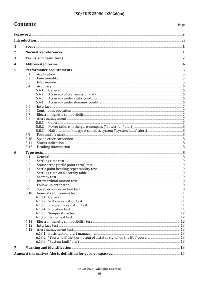
Contents Page
Foreword .v
Introduction .vi
1 Scope . 1
2 Normative references . 1
3 Terms and definitions . 2
4 Abbreviated terms . 4
5 Performance requirements . . 5
5.1 Application .5
5.2 Functionality .5
5.3 Information . .5
5.4 Accuracy .6
5.4.1 General .6
5.4.2 Accuracy of transmission data .6
5.4.3 Accuracy under static condition .6
5.4.4 Accuracy under dynamic condition .6
5.5 Interface .7
5.6 Continuous operation .7
5.7 Electromagnetic compatibility.7
5.8 Alert management .7
5.8.1 General .7
5.8.2 Power failure in the gyro-compass (“power fail” alert) .8
5.8.3 Malfunction of the gyro-compass system (“system fault” alert) .8
5.9 Fore and aft mark .8
5.10 Speed error correction .8
5.11 Status indication .8
5.12 Heading information .8
6 Type tests . 8
6.1 General .8
6.2 Settling time test .9
6.3 Static error (settle point error) test .9
6.4 Settle point heading repeatability test .9
6.5 Settling time on a Scorsby table .9
6.6 Scorsby test.9
6.7 Intercardinal motion test .10
6.8 Follow-up error test .10
6.9 Speed error correction test .10
6.10 General requirement test .11
6.10.1 General .11
6.10.2 Voltage variation test .11
6.10.3 Frequency variation test .11
6.10.4 Vibration test .11
6.10.5 Temperature test . 12
6.10.6 Damp heat test . . 12
6.11 Electromagnetic compatibility test . 12
6.12 Interface test . 13
6.13 Alert management test . 13
6.13.1 Basic test for alert management . 13
6.13.2 “Power fail” alert or output of a status signal on the EUT power . 13
6.13.3 “System fault” alert . 13
7 Marking and identification .13
Annex A (normative) Alerts definition for gyro-compasses . 14
iii
ISO/FDIS 22090-1:2026(en)
Annex B (normative) IEC 61162 series interfaces for VDR and other external equipment .15
Bibliography . 17
iv
ISO/FDIS 22090-1:2026(en)
Foreword
ISO (the International Organization for Standardization) is a worldwide federation of national standards
bodies (ISO member bodies). The work of preparing International Standards is normally carried out through
ISO technical committees. Each member body interested in a subject for which a technical committee
has been established has the right to be represented on that committee. International organizations,
governmental and non-governmental, in liaison with ISO, also take part in the work. ISO collaborates closely
with the International Electrotechnical Commission (IEC) on all matters of electrotechnical standardization.
The procedures used to develop this document and those intended for its further maintenance are described
in the ISO/IEC Directives, Part 1. In particular, the different approval criteria needed for the different types
of ISO document should be noted. This document was drafted in accordance with the editorial rules of the
ISO/IEC Directives, Part 2 (see www.iso.org/directives).
ISO draws attention to the possibility that the implementation of this document may involve the use of (a)
patent(s). ISO takes no position concerning the evidence, validity or applicability of any claimed patent
rights in respect thereof. As of the date of publication of this document, ISO had not received notice of (a)
patent(s) which may be required to implement this document. However, implementers are cautioned that
this may not represent the latest information, which may be obtained from the patent database available at
www.iso.org/patents. ISO shall not be held responsible for identifying any or all such patent rights.
Any trade name used in this document is information given for the convenience of users and does not
constitute an endorsement.
For an explanation of the voluntary nature of standards, the meaning of ISO specific terms and expressions
related to conformity assessment, as well as information about ISO's adherence to the World Trade
Organization (WTO) principles in the Technical Barriers to Trade (TBT), see www.iso.org/iso/foreword.html.
This document was prepared by Technical Committee ISO/TC 8, Ships and marine technology, Subcommittee
SC 6, Navigation and ship operations.
This third edition cancels and replaces the second edition (ISO 22090-1:2014), which has been technically
revised.
The main changes are as follows:
— Clause 4 (abbreviated terms) has been added;
— in 5.8, requirements related to bridge alert management have been added;
— in 6.1, a requirement for display equipment has been added;
— in 6.13, a test method for requirements related to bridge alert management has been added;
— Annex A has been replaced with a new Annex on alerts definition, including alert identifiers;
— in Annex B, an IEC 61162 series interfaces overview has been added;
— the normative references and bibliography have been updated.
A list of all parts in the ISO 22090 series can be found on the ISO website.
Any feedback or questions on this document should be directed to the user’s national standards body. A
complete listing of these bodies can be found at www.iso.org/members.html.
v
ISO/FDIS 22090-1:2026(en)
Introduction
This document is aligned with IMO Resolution MSC.116(73) on performance standards for marine
transmitting heading devices (THDs).
Any text in this document which is a citation from the IMO Resolution MSC.116(73), appears in italics.
Within these citations, any changes to the original wording of the IMO Resolution MSC.116(73) are written
in upright font.
In this document, the following verbal forms are used:
— “shall” indicates a requirement;
— “should” indicates a recommendation;
— “may” indicates a permission;
— “can” indicates a possibility or a capability.
The ISO 22090 series consists of the following parts, under the general title Ships and marine technology —
Transmitting heading devices (THDs):
— ISO 22090-1 (this document) ongyro-compasses;
— ISO 22090-2 on geomagnetic principles;
— ISO 22090-3 on GNSS principles.
vi
FINAL DRAFT International Standard ISO/FDIS 22090-1:2026(en)
Ships and marine technology — Transmitting heading devices
(THDs) —
Part 1:
Gyro-compasses
1 Scope
This document specifies general requirements, construction, performance and testing methods of
transmitting heading devices (THDs) using gyro-compasses, which are required to comply with the
International Convention for the Safety of Life at Sea (SOLAS) 1974 (as amended), Chapter V, and IMO
[ ]
Resolution MSC.116(73). 6
2 Normative references
The following documents are referred to in the text in such a way that some or all of their content constitutes
requirements of this document. For dated references, only the edition cited applies. For undated references,
the latest edition of the referenced document (including any amendments) applies.
IEC 60945, Marine navigation and radiocommunication equipment and systems — General requirements —
Methods of testing and required test results
IEC 61162-1, Maritime navigation and radiocommunication equipment and systems — Digital interfaces — Part
1: Single talker and multiple listeners
IEC 61162-2, Maritime navigation and radiocommunication equipment and systems — Digital interfaces — Part
2: Single talker and multiple listeners, high-speed transmission
IEC 61162-450, Maritime navigation and radiocommunication equipment and systems - Digital interfaces - Part
450: Multiple talkers and multiple listeners - Ethernet interconnection
IEC 62288, Maritime navigation and radiocommunication equipment and systems — Presentation of navigation-
related information on shipborne navigational displays — General requirements, methods of testing and required
test results
IEC 62923-1, Maritime navigation and radiocommunication equipment and systems — Bridge alert management
— Part 1: Operational and performance requirements, methods of testing and required test results
IEC 62923-2, Maritime navigation and radiocommunication equipment and systems — Bridge alert management
— Part 2: Alert and cluster identifiers and other additional features
IMO Resolution MSC.116(73), Performance standards for marine transmitting heading devices (THDs)
IMO Resolution MSC.302(87), Adoption of performance standards for bridge alert management
IMO Resolution A.424(XI), Performance standards for gyro-compasses
IMO Resolution A.694(17), General requirements for shipborne radio equipment forming part of the global
maritime distress and safety system (GMDSS) and for electronic navigational aids
IMO Resolution A.813(19), General requirements for electromagnetic compatibility (EMC) for all electrical and
electronic ship’s equipment
IMO Resolution A.821(19), Performance standards for gyro-compasses for high-speed craft
ISO/FDIS 22090-1:2026(en)
IMO Resolution MSC.191(79), Performance standards for the presentation of navigation-related information on
shipborne navigational displays
HSC Code, Chapter 13
3 Terms and definitions
For the purposes of this document, the following terms and definitions apply.
ISO and IEC maintain terminology databases for use in standardization at the following addresses:
— ISO Online browsing platform: available at https:// www .iso .org/ obp
— IEC Electropedia: available at https:// www .electropedia .org/
3.1
transmitting heading device
THD
electronic device that provides information about the ship’s true heading (3.6)
Note 1 to entry: Several technologies can be used to detect and transmit heading information. It is illogical to
standardize the detection of the heading separately from the transmission of the heading. Therefore, separate parts of
this document refer to different technologies. The requirements of this document only apply to gyroscopic technology.
Other technologies are covered in other parts of the ISO 22090 series.
[SOURCE: IMO Resolution MSC.116(73), 1.1— note 1 to entry has been added.]
3.2
gyro-compass
complete equipment comprising all essential elements of the complete design including both the gyro-
compass as heading sensor and the associated heading transmission system
3.3
heading
ship’s heading to be input to the transmitting heading device (3.1) function
Note 1 to entry: It is defined by the direction of the vertical projection of the fore and aft line of the ship onto the
horizontal plane. When measured relative to the true north, magnetic north, or compass north, it is respectively
defined as true heading, magnetic heading, or compass heading, and is usually expressed in degrees as a three-figure
group, starting from north, in a clockwise direction around the compass card.
[SOURCE: IMO Resolution MSC.116(73), 3.1]
3.4
sensing part
sensing function of detecting any heading information connected to the transmitting part (3.5)
[SOURCE: IMO Resolution MSC.116(73), 3.2]
3.5
transmitting part
device which receives heading information from the sensing part (3.4) and converts this to the required
accurate signal
[SOURCE: IMO Resolution MSC.116(73), 3.3]
3.6
true heading
horizontal angle between the vertical plane passing through the true meridian and the vertical plane passing
through the craft’s fore and aft datum line
Note 1 to entry: The true heading is measured from true north (000°) clockwise through 360°.
ISO/FDIS 22090-1:2026(en)
[SOURCE: IMO Resolution MSC.116(73), 3.4 — note 1 to entry has been added.]
3.7
transmission and resolution error
error which is caused by the method used to transmit the original information to a receiving device
Note 1 to entry: Such a method may have a limited capability to code any possible value of the information, e.g. step
output with 1/6° resolution. This error is also caused by the method used inside the transmitting heading device (3.1)
and at its output to code the information.
[SOURCE: IMO Resolution MSC.116(73), 3.5, modified — note 1 to entry has been added.]
3.8
static error
error caused by any reason and which stays unchanged in value during the operation of the system,
measured under static conditions
Note 1 to entry: This static error is considered to be the same as that defined in the settle point error (3.13) for gyro-
compasses.
[SOURCE: IMO Resolution MSC.116(73), 3.6 — note 1 to entry has been added.]
3.9
dynamic error
error (3.14) caused by dynamic influences acting on the system, such as vibration, roll, pitch, or linear
acceleration
Note 1 to entry: This error may have an amplitude and usually a frequency related to the environmental influences
and the parameters of the system itself.
Note 2 to entry: This dynamic error is considered to be the same as that defined in the error (3.14) for gyro-compasses.
[SOURCE: IMO Resolution MSC.116(73), 3.7, modified — notes 1 and 2 to entry have been added.]
3.10
follow-up error
error caused by the delay between the existence of a value to be sensed and the availability of the
corresponding signal or data stream at the output of the system
EXAMPLE The difference between the real heading of a turning vessel and the available information at the output
of the system.
Note 1 to entry: A follow-up error disappears when the system is static.
[SOURCE: IMO Resolution MSC.116(73), 3.8, modified — EXAMPLE and note 1 to entry have been added.]
3.11
settled
stable situation when any three readings taken at intervals of 30 min are within a band of 0,7°, with the
compass level and stationary
Note 1 to entry: The settling time is the elapsed time between the time of switch-on at the initial heading error and the
third recording of the settle.
3.12
settle point heading
mean value of ten readings taken at 20 min intervals after the compass has settled (3.11)
3.13
settle point error
difference between the settle point heading (3.12) and the true heading (3.6)
Note 1 to entry: See static error (3.8).
ISO/FDIS 22090-1:2026(en)
3.14
error
difference between the observed value and the settle point heading (3.12)
Note 1 to entry: See dynamic error (3.9).
Note 2 to entry: In this document, if the true heading (3.6) is unknown — other than in the case of a settle point error
(3.13) (the difference from the true heading) — quantitative heading error is evaluated using the settle point heading
instead of the true heading defined here.
3.15
latitude error
error to which some gyro-compasses (3.2) are subject, the magnitude and sign of which depend upon the
local latitude
Note 1 to entry: Means are provided for correcting this error.
3.16
speed error
error to which gyro-compasses (3.2) are subject, the magnitude and sign of which depend upon the speed,
course, and latitude of the ship
Note 1 to entry: Means are provided for correcting this error.
3.17
master compass
main compass unit which supplies the heading information to the transmitting part or other navigational
aids
3.18
Scorsby table
test machine which enables a platform to oscillate independently about three axes
Note 1 to entry: It is used to simulate the motion of a ship.
3.19
intercardinal motion
representation of an integral motion of the ship, which is used for an error test within motion in a dynamic
simulation test
3.20
bridge alert management
BAM
overall concept for management, handling and harmonized presentation of alerts on the bridge
[SOURCE: IMO Resolution MSC.302(87), Appendix 1]
3.21
central alert management system
CAM system
combined functionality of the central alert management and the central alert management human machine
interface
[SOURCE: IMO Resolution MSC.302(87), Appendix 1]
4 Abbreviated terms
For the purposes of this document, the following abbreviated terms apply.
ISO/FDIS 22090-1:2026(en)
BAM bridge alert management
CAM central alert management
EUT equipment under test
GC gyro-compass
GNSS global navigation satellite system
SDME speed and distance measuring equipment
VDR Voyage data recorder
5 Performance requirements
5.1 Application
Transmitting heading devices (THDs) shall comply with IMO Resolution MSC.116(73).
In accordance with IMO Resolution MSC.116(73), 1.2 and 1.3, in addition to the general requirements contained
in IMO Resolution A.694(17) to which IEC 60945 is associated and the relevant standard for the sensing part
used, the THD equipment shall comply with the following minimum requirements.
Where the IMO performance standards that apply to the sensing part do not specify a geographical operating
area, the THD shall operate:
a) at maximum rate of turn 20°/s, and
b) from 70° latitude south to 70° latitude north as minimum.
In accordance with IMO Resolution MSC.116(73), 2.1, the THDs complying with the requirements contained in
[6]
this document can be used for heading information as contained in Chapter V of the SOLAS Convention.
1)
However, ships within a speed range of 30 kn to 70 kn shall comply wit
...
ISO/FDIS 22090-1:2026(en)
ISO/TC 8/SC 6
Secretariat: JISC
Date: 2026-04-3007-09
Ships and marine technology — Transmitting heading devices
(THDs) —
Part 1:
Gyro-compasses
Navires et technologie maritime — Dispositifs de pilotage à transmission de données —
Partie 1: Compas gyroscopiques
FDIS stage
ISO/FDIS 22090-1:2026(en)
All rights reserved. Unless otherwise specified, or required in the context of its implementation, no part of this publication
may be reproduced or utilized otherwise in any form or by any means, electronic or mechanical, including photocopying,
or posting on the internet or an intranet, without prior written permission. Permission can be requested from either ISO
at the address below or ISO’s member body in the country of the requester.
ISO copyright office
CP 401 • Ch. de Blandonnet 8
CH-1214 Vernier, Geneva
Phone: + 41 22 749 01 11
EmailE-mail: copyright@iso.org
Website: www.iso.org
Published in Switzerland
ii
ISO/FDIS 22090-1:2026(en)
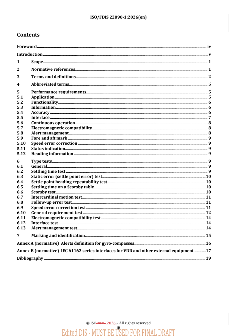
Contents
Foreword . iv
Introduction . v
1 Scope . 1
2 Normative references . 1
3 Terms and definitions . 2
4 Abbreviated terms . 5
5 Performance requirements . 5
5.1 Application . 5
5.2 Functionality . 6
5.3 Information . 6
5.4 Accuracy . 6
5.5 Interface . 7
5.6 Continuous operation . 8
5.7 Electromagnetic compatibility . 8
5.8 Alert management . 8
5.9 Fore and aft mark . 9
5.10 Speed error correction . 9
5.11 Status indication. 9
5.12 Heading information . 9
6 Type tests . 9
6.1 General. 9
6.2 Settling time test . 9
6.3 Static error (settle point error) test . 10
6.4 Settle point heading repeatability test . 10
6.5 Settling time on a Scorsby table . 10
6.6 Scorsby test . 10
6.7 Intercardinal motion test . 11
6.8 Follow-up error test . 11
6.9 Speed error correction test . 11
6.10 General requirement test . 12
6.11 Electromagnetic compatibility test . 14
6.12 Interface test . 14
6.13 Alert management test . 14
7 Marking and identification . 15
Annex A (normative) Alerts definition for gyro-compasses . 16
Annex B (normative) IEC 61162 series interfaces for VDR and other external equipment . 17
Bibliography . 19
iii
ISO/FDIS 22090-1:2026(en)
Foreword
ISO (the International Organization for Standardization) is a worldwide federation of national standards
bodies (ISO member bodies). The work of preparing International Standards is normally carried out through
ISO technical committees. Each member body interested in a subject for which a technical committee has been
established has the right to be represented on that committee. International organizations, governmental and
non-governmental, in liaison with ISO, also take part in the work. ISO collaborates closely with the
International Electrotechnical Commission (IEC) on all matters of electrotechnical standardization.
The procedures used to develop this document and those intended for its further maintenance are described
in the ISO/IEC Directives, Part 1. In particular, the different approval criteria needed for the different types of
ISO document should be noted. This document was drafted in accordance with the editorial rules of the
ISO/IEC Directives, Part 2 (see www.iso.org/directives).
ISO draws attention to the possibility that the implementation of this document may involve the use of (a)
patent(s). ISO takes no position concerning the evidence, validity or applicability of any claimed patent rights
in respect thereof. As of the date of publication of this document, ISO had not received notice of (a) patent(s)
which may be required to implement this document. However, implementers are cautioned that this may not
represent the latest information, which may be obtained from the patent database available at
www.iso.org/patents. ISO shall not be held responsible for identifying any or all such patent rights.
Any trade name used in this document is information given for the convenience of users and does not
constitute an endorsement.
For an explanation of the voluntary nature of standards, the meaning of ISO specific terms and expressions
related to conformity assessment, as well as information about ISO's adherence to the World Trade
Organization (WTO) principles in the Technical Barriers to Trade (TBT), see www.iso.org/iso/foreword.html.
This document was prepared by Technical Committee ISO/TC 8, Ships and marine technology, Subcommittee
SC 6, Navigation and ship operations.
This third edition cancels and replaces the second edition (ISO 22090-1:2014), which has been technically
revised.
The main changes are as follows:
— Clause 4 (abbreviated terms) has been added;
— Clause 4
— — in 5.85.8,, requirements related to bridge alert management have been added;
— — in 6.16.1,, a requirement for display equipment has been added;
— — in 6.136.13,, a test method for requirements related to bridge alert management has been added;
— Annex A— Annex A has been replaced with a new Annex on alerts definition, including alert identifiers;
— — in Annex BAnnex B,, an IEC 61162 series interfaces overview has been added;
— — the normative references and bibliography have been updated.
A list of all parts in the ISO 22090 series can be found on the ISO website.
Any feedback or questions on this document should be directed to the user’s national standards body. A
complete listing of these bodies can be found at www.iso.org/members.html.
iv
ISO/FDIS 22090-1:2026(en)
Introduction
This document is aligned with IMO Resolution MSC.116(73) on performance standards for marine
transmitting heading devices (THDs).
Any text in this document which is a citation from the IMO Resolution MSC.116(73), appears in italics. Within
these citations, any changes to the original wording of the IMO Resolution MSC.116(73) are written in upright
font.
In this document, the following verbal forms are used:
— — “shall” indicates a requirement;
— — “should” indicates a recommendation;
— — “may” indicates a permission;
— — “can” indicates a possibility or a capability.
The ISO 22090 series consists of the following parts, under the general title Ships and marine technology —
Transmitting heading devices (THDs):
— — Part ISO 22090-1: Gyro (this document) ongyro-compasses;
— — Part ISO 22090-2: Geomagnetic on geomagnetic principles;
— — Part ISO 22090-3: on GNSS principles.
v
Final DRAFT International Standard ISO/FDIS 22090-1:2026(en)
Ships and marine technology — Transmitting heading devices
(THDs) —
Part 1:
Gyro-compasses
1 Scope
This document specifies general requirements, construction, performance and testing methods of
transmitting heading devices (THDs) using gyro-compasses, which are required to comply with the
International Convention for the Safety of Life at Sea (SOLAS) 1974 (as amended), chapterChapter V, and IMO
[[6]
Resolution MSC.116(73).
2 Normative references
The following documents are referred to in the text in such a way that some or all of their content constitutes
requirements of this document. For dated references, only the edition cited applies. For undated references,
the latest edition of the referenced document (including any amendments) applies.
IEC 60945, Marine navigation and radiocommunication equipment and systems — General requirements —
Methods of testing and required test results
IEC 61162--1, Maritime navigation and radiocommunication equipment and systems — Digital interfaces —
Part 1: Single talker and multiple listeners
IEC 61162--2, Maritime navigation and radiocommunication equipment and systems — Digital interfaces —
Part 2: Single talker and multiple listeners, high-speed transmission
IEC 61162--450, Maritime navigation and radiocommunication equipment and systems - Digital interfaces - Part
450: Multiple talkers and multiple listeners - Ethernet interconnection
IEC 62288, Maritime navigation and radiocommunication equipment and systems — Presentation of navigation-
related information on shipborne navigational displays — General requirements, methods of testing and required
test results
IEC 62923--1, Maritime navigation and radiocommunication equipment and systems — Bridge alert
management — Part 1: Operational and performance requirements, methods of testing and required test results
IEC 62923--2, Maritime navigation and radiocommunication equipment and systems — Bridge alert
management — Part 2: Alert and cluster identifiers and other additional features
IMO Resolution MSC.116(73), Performance standards for marine transmitting heading devices (THDs)
IMO Resolution MSC.302(87), Adoption of performance standards for bridge alert management
IMO Resolution A.424(XI), Performance standards for gyro-compasses
IMO Resolution A.694(17), General requirements for shipborne radio equipment forming part of the global
maritime distress and safety system (GMDSS) and for electronic navigational aids
ISO/FDIS 22090-1:2026(en)
IMO Resolution A.813(19), General requirements for electromagnetic compatibility (EMC) for all electrical and
electronic ship’s equipment
IMO Resolution A.821(19), Performance standards for gyro-compasses for high-speed craft
IMO Resolution MSC.191(79), Performance standards for the presentation of navigation-related information on
shipborne navigational displays
IMO Resolution MSC 466(101), Amendments to the performance standards for the presentation of navigation-
related information on shipborne navigational displays (Resolution MSC.191(79))
HSC Code, chapterChapter 13
3 Terms and definitions
For the purposes of this document, the following terms and definitions apply.
ISO and IEC maintain terminology databases for use in standardization at the following addresses:
— — ISO Online browsing platform: available at https://www.iso.org/obp
— — IEC Electropedia: available at https://www.electropedia.org/
3.1 3.1
transmitting heading device
THD
electronic device that provides information about the ship’s true heading (3.6(3.6))
Note 1 to entry: Several technologies can be used to detect and transmit heading information. It is illogical to standardize
the detection of the heading separately from the transmission of the heading. Therefore, separate parts of this document
refer to different technologies. The requirements of this document only apply to gyroscopic technology. Other
technologies are covered in other parts of the ISO 22090 series.
[SOURCE: IMO Resolution MSC.116(73), 1.1— note 1 to entry has been added.]
3.2 3.2
gyro-compass
complete equipment comprising all essential elements of the complete design including both the gyro-
compass as heading sensor and the associated heading transmission system
3.3 3.3
heading
ship’s heading to be input to the transmitting heading device (3.1(3.1)) function
Note 1 to entry: It is defined by the direction of the vertical projection of the fore and aft line of the ship onto the
horizontal plane. When measured relative to the true north, magnetic north, or compass north, it is respectively defined
as true heading, magnetic heading, or compass heading, and is usually expressed in degrees as a three-figure group,
starting from north, in a clockwise direction around the compass card.
[SOURCE: IMO Resolution MSC.116(73), 3.1]
3.4 3.4
sensing part
sensing function of detecting any heading information connected to the transmitting part (3.5)
[SOURCE: IMO Resolution MSC.116(73), 3.2]
ISO/FDIS 22090-1:2026(en)
3.5 3.5
transmitting part
device which receives heading information from the sensing part (3.4) and converts this to the required
accurate signal
[SOURCE: IMO Resolution MSC.116(73), 3.3]
3.6 3.6
true heading
horizontal angle between the vertical plane passing through the true meridian and the vertical plane passing
through the craft’s fore and aft datum line
Note 1 to entry: The true heading is measured from true north (000°) clockwise through 360°.
[SOURCE: IMO Resolution MSC.116(73), 3.4 — note 1 to entry has been added.]
3.7 3.7
transmission and resolution error
error which is caused by the method used to transmit the original information to a receiving device
Note 1 to entry: Such a method may have a limited capability to code any possible value of the information, e.g. step
output with 1/6° resolution. This error is also caused by the method used inside the transmitting heading device (3.1(3.1))
and at its output to code the information.
[SOURCE: IMO Resolution MSC.116(73), 3.5, modified — note 1 to entry has been added.]
3.8 3.8
static error
error caused by any reason and which stays unchanged in value during the operation of the system, measured
under static conditions
Note 1 to entry: This static error is considered to be the same as that defined in the settle point error (3.13(3.13)) for
Gyrogyro-compasses.
[SOURCE: IMO Resolution MSC.116(73), 3.6 — note 1 to entry has been added.]
3.9 3.9
dynamic error
error (3.14) caused by dynamic influences acting on the system, such as vibration, roll, pitch, or linear
acceleration
Note 1 to entry: This error may have an amplitude and usually a frequency related to the environmental influences and
the parameters of the system itself.
Note 2 to entry: This dynamic error is considered to be the same as that defined in the error (3.14(3.14)) for Gyrogyro-
compasses.
[SOURCE: IMO Resolution MSC.116(73), 3.7, modified — notes 1 and 2 to entry have been added.]
3.10 3.10
follow-up error
error caused by the delay between the existence of a value to be sensed and the availability of the
corresponding signal or data stream at the output of the system
EXAMPLE The difference between the real heading of a turning vessel and the available information at the output
of the system.
ISO/FDIS 22090-1:2026(en)
Note 1 to entry: A follow-up error disappears when the system is static.
[SOURCE: IMO Resolution MSC.116(73), 3.8, modified — EXAMPLE and note 1 to entry have been added.]
3.11 3.11
settled
stable situation when any three readings taken at intervals of 30 min are within a band of 0,7°, with the
compass level and stationary
Note 1 to entry: The settling time is the elapsed time between the time of switch-on at the initial heading error and the
third recording of the settle.
3.12 3.12
settle point heading
mean value of ten readings taken at 20 min intervals after the compass has settled (3.11(3.11))
3.13 3.13
settle point error
difference between the settle point heading (3.12(3.12)) and the true heading (3.6(3.6))
Note 1 to entry: See static error (3.8(3.8).).
3.14
error (other than settle point error(3.13))
3.14
error
difference between the observed value and the settle point heading (3.12(3.12))
Note 1 to entry: See dynamic error (3.9(3.9)).
Note 2 to entry: In this document, if the true heading (3.6) is unknown — other than in the case of a
settle point error (3.133.15
) (the difference from the true heading) — quantitative heading error is evaluated using the settle point heading instead
of the true heading defined here.
3.15
latitude error
error to which some gyro-compasses (3.2(3.2)) are subject, the magnitude and sign of which depend upon the
local latitude
Note 1 to entry: Means are provided for correcting this error.
3.143.16 3.16
speed error
error to which gyro-compasses (3.2(3.2)) are subject, the magnitude and sign of which depend upon the speed,
course, and latitude of the ship
Note 1 to entry: Means are provided for correcting this error.
3.153.17 3.17
master compass
main compass unit which supplies the heading information to the transmitting part or other navigational aids
3.163.18 3.18
Scorsby table
test machine which enables a platform to oscillate independently about three axes
ISO/FDIS 22090-1:2026(en)
Note 1 to entry: It is used to simulate the motion of a ship.
3.173.19 3.19
intercardinal motion
representation of an integral motion of the ship, which is used for an error test within motion in a dynamic
simulation test
3.183.20 3.20
bridge alert management
BAM
overall concept for management, handling and harmonized presentation of alerts on the bridge
[SOURCE: IMO Resolution MSC.302(87), Appendix 1]
3.193.21 3.21
central alert management system
CAM system
combined functionality of the central alert management and the central alert management human machine
interface
[SOURCE: IMO Resolution MSC.302(87), Appendix 1]
4 Abbreviated terms
For the purposes of this document, the following abbreviated terms apply.
BAM bridge alert management
CAM central alert management
EUT equipment under test
GC gyro-compass
GNSS global navigation satellite system
SDME speed and distance measuring equipment
VDR Voyage data recorder
5 Performance requirements
5.1 Application
Transmitting heading devices (THDs) shall comply with IMO Resolution MSC.116(73).
In accordance with IMO Resolution MSC.116(73), 1.2 and 1.3, in addition to the general requirements contained
in IMO Resolution A.694(17) to which IEC 60945 is associated and the relevant standard for the sensing part
used, the THD equipment shall comply with the following minimum requirements.
Where the IMO performance standards that apply to the sensing part do not specify a geographical operating
area, the THD shall operate:
a) a) at maximum rate of turn 20°/s, and
b) b) from 70° latitude south to 70° latitude north as minimum.
ISO/FDIS 22090-1:2026(en)
In accordance with IMO Resolution MSC.116(73), 2.1, the THDs complying with the requirements contained in
this document can be used for heading information as contained in chapterChapter V of the SOLAS
[4] [6]
Convention .
11)
However, ships within a speed range of 30 kn to 70 kn shall comply with the requirements of IMO Resolution
A.821(19).
In accordance with IMO Resolution MSC.116(73), 2.2, in addition, such THD shall meet the dynamic
requirements contained in the HSC Code, chapterChapter 13 for the carriage of a suitable device providing
heading information.
5.2 Functionality
In this document, the gyro-compass is specified as the function of THD.
In accordance with IMO Resolution MSC.116(73), 4.1.1, the THD generates a heading signal and outputs a
suitable signal for other devices.
In accordance with IMO Resolution MSC.116(73), 4.1.2, any sensing part may be included in the device.
In accordance with IMO Resolution MSC.116(73), 4.1.3, if any correcting devices or parameters have been
associated, they shall be protected against inadvertent operation.
5.3 Information
In accordance with IMO Resolution MSC.116(73), 4.2.1, all displays with the exception of the sensor, and all
outputs of heading shall indicate true heading.
Indication shall be displayed, readable to a tenth of a degree.
In accordance with IMO Resolution MSC.116(73), 4.2.2, manually entered values used for electronic correction
shall be indicated by adequate means.
5.4 Accuracy
5.4.1 General
In accordance with IMO Resolution MSC.116(73), 4.3.1, the THD shall be tested for accuracy with the sensing
part connected. If the sensing part is so designed that it is included in the transmitting part, the equipment shall
be tested at all parts.
In accordance with IMO Resolution MSC.116(73), 4.3.2 and to maintain performance as a gyrocompass, the
THD shall meet at least the following accuracy (All from 5.4.2specified in 5.4.2 to 5.4.4 5.4.4)at the output of the
device under sea conditions as specified in IMO Resolution A.424(XI) or A.821(19) as applicable.
5.4.2 Accuracy of transmission data
In accordance with IMO Resolution MSC.116(73), 4.3.2.1, the transmission error, including the resolution error,
shall be less than ± 0,2°.
1 kn = 1,852 km/h.
1)
1 kn = 1,852 km/h.
ISO/FDIS 22090-1:2026(en)
5.4.3 Accuracy under static condition
5.4.3.1 Settling time under static condition
When switched on in accordance with the manufacturer's instructions, the compass shall settle within 6 h.
5.4.3.2 Static error (settle point error)
In accordance with IMO Resolution MSC.116(73), 4.3.2.2, the static error (settle point error) at any heading
shall be less than ± 1,0° × secant latitude, and the RMS value of the differences between individual heading
indications and the mean value shall be less than 0,35° × secant latitude.
The repeatability of settle point error from one run-up to another shall be within 0,35° × secant latitude.
5.4.4 Accuracy under dynamic condition
5.4.4.1 Settling time under dynamic condition
When switched on in accordance with the manufacturer's instructions, the compass shall settle within 6 h
when rolling and pitching with simple harmonic motion of any period between 6 s and 15 s, a maximum angle
of 5°, and a maximum horizontal acceleration of 0,22 m/s .
5.4.4.2 Dynamic error
In accordance with IMO Resolution MSC.116(73), 4.3.2.
...