

ISO/FDIS 25160
(Main)Testing method for hose reinforcement wire
- Abstract
This document specifies test methods of round steel hose reinforcement wire which are used for hose reinforcement. Test methods on mechanical properties and chemical properties (coating analysis) are included. By agreement, these test methods may be applied to similar single filaments used for reinforcement other rubber products.
- Status
- Not Published
- Technical Committee
- ISO/TC 17/SC 17 - Steel wire rod and wire products
- Drafting Committee
- ISO/TC 17/SC 17 - Steel wire rod and wire products
- Current Stage
- 5020 - FDIS ballot initiated: 2 months. Proof sent to secretariat
- Start Date
- 04-Sep-2026
- Completion Date
- 04-Sep-2026
Buy Documents
ISO/FDIS 25160 - Testing method for hose reinforcement wire
REDLINE ISO/FDIS 25160 - Testing method for hose reinforcement wire
ISO/FDIS 25160 is an ISO document for testing round steel hose reinforcement wire used in hose reinforcement. It sets out test methods for mechanical properties and coating analysis so producers, laboratories, and buyers can measure the wire in a consistent way. By agreement, the same methods can also be applied to similar single filaments used to reinforce other rubber products.
What does ISO/FDIS 25160 specify?
ISO/FDIS 25160 specifies test methods for round steel hose reinforcement wire, including mechanical tests and chemical property checks through coating analysis. The scope also allows the methods to be used, by agreement, for similar single filaments in other rubber-product reinforcement.
ISO/FDIS 25160 is organized into clauses on scope, normative references, terms and definitions, and then the individual test methods. The main technical clauses cover diameter, breaking force and yield force and elongation, knot strength, torsion resistance, reverse bending or flexions, cast and dead cast, and determination of coating mass and composition.
| Clause / topic | What it covers |
|---|---|
| 4 Diameter | Micrometer and non-contact laser measurement methods |
| 5 Breaking force and yield force and elongation | Tensile testing method and reporting |
| 6 Knot strength | Tensile test with a knot for small-diameter wire |
| 7 Torsion resistance | Simple torsion test and reporting |
| 8 Reverse bending or flexions | Repeated bend test and reporting |
| 9 Cast and dead cast | Cast and tip rise measurement |
| 10 Coating analysis | XRFS and AAS methods for coating mass, composition, and thickness |
What are the key requirements of ISO/FDIS 25160?
ISO/FDIS 25160 focuses on making the wire testable in a repeatable way. The practical requirements are about sample preparation, test setup, controlled loading, and how to report the result so different laboratories can compare data.
Diameter measurement
Clause 4 gives two diameter methods: a micrometer method and a non-contact laser method. For micrometer testing, the wire sample must be clean and as straight as possible, the micrometer must be zeroed before each test series, and measurements are taken at multiple wire orientations so the result reflects the actual diameter and, when needed, out-of-roundness. For laser measurement, the document requires 0.001 mm resolution, a perpendicular sample position, and multiple angles or rotation during measurement. In practice, this tells a lab whether it needs average diameter only or also ovality.
Tensile properties
Clause 5 covers breaking force, yield force, and elongation in a Constant-Rate-of-Extension (CRE) tensile test. The method uses defined grips, an extensometer, and, when requested, elevated-temperature testing in an oven. The sample must be straight and undamaged, preload and test speed depend on wire size and gauge length, and clamp failures make the test invalid. In practice, this clause is the main basis for checking wire strength, ductility, and supplier consistency.
Knot strength
Clause 6 uses a tensile test with a simple overhand knot in the middle of the specimen. It applies to wire with a diameter less than or equal to 0.82 mm, and it is described as especially suitable for wires below 0.50 mm. The test is a ductility and defect-sensitive check, because weak or damaged wire lowers knot strength. In practice, this is a screening test for small wire that may see severe forming or bending.
Torsion resistance
Clause 7 measures how many turns a single filament can take before fracture in simple torsion. The wire must be straight and free of localized sharp curvature, the axial load must stay low, and the speed and free length are controlled. The clause also gives validation rules for fractures near the grip area and requires the number of complete turns to be reported. In practice, this helps judge plastic deformation capacity and detect brittle or damaged wire.
Reverse bending or flexions
Clause 8 uses alternating 90° bends over cylindrical supports until fracture occurs. The wire is held under tension in a vertical test position, and the bending sequence continues right and left until breakage. The document also allows thermal aging before testing when agreed. In practice, this method is a fatigue-type ductility check for wire that must tolerate repeated directional bending.
Cast and dead cast
Clause 9 describes a simple way to measure the natural circular cast of the wire and the tip rise. The test uses a smooth table surface and a ruler with 1 mm resolution. In practice, these measurements help assess how the wire behaves in handling and forming, and how much it tends to stay curved after drawing.
Coating mass, composition, and thickness
Clause 10 gives two analytical routes for brass coating: X-ray fluorescent spectrometers (XRFS) and atomic absorption spectrometry (AAS). Both methods require defined sample preparation, calibration standards, and dissolution of the coating before measurement, then calculation of coating mass, copper content, and thickness. In practice, these methods are used to verify coating quality and consistency, which matters for corrosion protection and downstream processing.
What terms does ISO/FDIS 25160 define?
- Breaking force - the force level at fracture, expressed in N, which shows the load the wire withstands before breaking.
- Maximum force - the highest force the test piece withstands, expressed in N, which is used in tensile and knot testing results.
- Elongation - the total extension at break divided by the original specimen length, expressed as a percentage, which indicates ductility.
- Yield force - the force level at 0.2 % permanent elongation offset, expressed in N, which marks the start of plastic deformation.
- Cast - the natural circular curve of drawn wire, described by its free inner diameter.
- Tip rise - the amount the loose end of the wire stands out of plane from the table in the cast test.
- X-ray fluorescent spectrometers (XRFS) - instruments used to determine coating composition by X-ray fluorescence.
- Atomic absorption spectrometry (AAS) - an analytical method used here to measure copper and zinc in dissolved coating solutions.
Who uses ISO/FDIS 25160?
ISO/FDIS 25160 is used by wire manufacturers, hose makers, and test laboratories that need to check the properties of hose reinforcement wire. Quality managers use it for incoming inspection, in-process control, and release testing. Buyers and technical specifiers use it when they need a common test language for supplier comparison or acceptance criteria. It is also relevant to laboratories that measure coating mass and composition and to engineers evaluating wire performance in bending, torsion, and tensile loading.
Which standards are used with ISO/FDIS 25160?
- ISO 7800:2012 - provides the simple torsion test framework used for torsion testing and, where needed, fracture characterization.
- ISO 23717 - provides the base terminology for steel wire and wire products - hose reinforcement wire, which the terms and definitions clause relies on.
What does the ISO/FDIS 25160 document contain?
ISO/FDIS 25160 contains step-by-step test methods, apparatus descriptions, sample preparation rules, test settings, result calculations, and reporting instructions for each method. It includes figures for micrometer measurement, tensile behavior, knot testing, torsion, reverse bending, cast, and tip rise. It also includes tables for example bending-device parameters and calibration or standard solutions used in coating analysis. The coating section provides formulas for converting instrument readings into coating mass, composition, and thickness, which supports laboratory testing and quality verification.
Buy Documents
ISO/FDIS 25160 - Testing method for hose reinforcement wire
REDLINE ISO/FDIS 25160 - Testing method for hose reinforcement wire
Get Certified
Connect with accredited certification bodies for this standard

Element Materials Technology
Materials testing and product certification.

Inštitut za kovinske materiale in tehnologije
Institute of Metals and Technology. Materials testing, metallurgical analysis, NDT.
Sponsored listings
Frequently Asked Questions
ISO/FDIS 25160 is a draft published by the International Organization for Standardization (ISO). Its full title is "Testing method for hose reinforcement wire". This standard covers: This document specifies test methods of round steel hose reinforcement wire which are used for hose reinforcement. Test methods on mechanical properties and chemical properties (coating analysis) are included. By agreement, these test methods may be applied to similar single filaments used for reinforcement other rubber products.
This document specifies test methods of round steel hose reinforcement wire which are used for hose reinforcement. Test methods on mechanical properties and chemical properties (coating analysis) are included. By agreement, these test methods may be applied to similar single filaments used for reinforcement other rubber products.
ISO/FDIS 25160 is classified under the following ICS (International Classification for Standards) categories: 77.140.65 - Steel wire, wire ropes and link chains. The ICS classification helps identify the subject area and facilitates finding related standards.
ISO/FDIS 25160 is available in PDF format for immediate download after purchase. The document can be added to your cart and obtained through the secure checkout process. Digital delivery ensures instant access to the complete standard document.
Standards Content (Sample)
FINAL DRAFT
International
Standard
ISO/TC 17/SC 17
Testing method for hose
Secretariat: SAC
reinforcement wire
Voting begins on:
Méthode d'essai pour le fil de renforcement des tuyaux 2026-09-04
Voting terminates on:
2026-10-30
RECIPIENTS OF THIS DRAFT ARE INVITED TO SUBMIT,
WITH THEIR COMMENTS, NOTIFICATION OF ANY
RELEVANT PATENT RIGHTS OF WHICH THEY ARE AWARE
AND TO PROVIDE SUPPOR TING DOCUMENTATION.
IN ADDITION TO THEIR EVALUATION AS
BEING ACCEPTABLE FOR INDUSTRIAL, TECHNO
LOGICAL, COMMERCIAL AND USER PURPOSES, DRAFT
INTERNATIONAL STANDARDS MAY ON OCCASION HAVE
TO BE CONSIDERED IN THE LIGHT OF THEIR POTENTIAL
TO BECOME STAN DARDS TO WHICH REFERENCE MAY BE
MADE IN NATIONAL REGULATIONS.
Reference number
FINAL DRAFT
International
Standard
ISO/TC 17/SC 17
Testing method for hose
Secretariat: SAC
reinforcement wire
Voting begins on:
Méthode d'essai pour le fil de renforcement des tuyaux
Voting terminates on:
RECIPIENTS OF THIS DRAFT ARE INVITED TO SUBMIT,
WITH THEIR COMMENTS, NOTIFICATION OF ANY
RELEVANT PATENT RIGHTS OF WHICH THEY ARE AWARE
AND TO PROVIDE SUPPOR TING DOCUMENTATION.
© ISO 2026
IN ADDITION TO THEIR EVALUATION AS
All rights reserved. Unless otherwise specified, or required in the context of its implementation, no part of this publication may
BEING ACCEPTABLE FOR INDUSTRIAL, TECHNO
LOGICAL, COMMERCIAL AND USER PURPOSES, DRAFT
be reproduced or utilized otherwise in any form or by any means, electronic or mechanical, including photocopying, or posting on
INTERNATIONAL STANDARDS MAY ON OCCASION HAVE
the internet or an intranet, without prior written permission. Permission can be requested from either ISO at the address below
TO BE CONSIDERED IN THE LIGHT OF THEIR POTENTIAL
or ISO’s member body in the country of the requester.
TO BECOME STAN DARDS TO WHICH REFERENCE MAY BE
MADE IN NATIONAL REGULATIONS.
ISO copyright office
CP 401 • Ch. de Blandonnet 8
CH-1214 Vernier, Geneva
Phone: +41 22 749 01 11
Email: copyright@iso.org
Website: www.iso.org
Published in Switzerland Reference number
ii
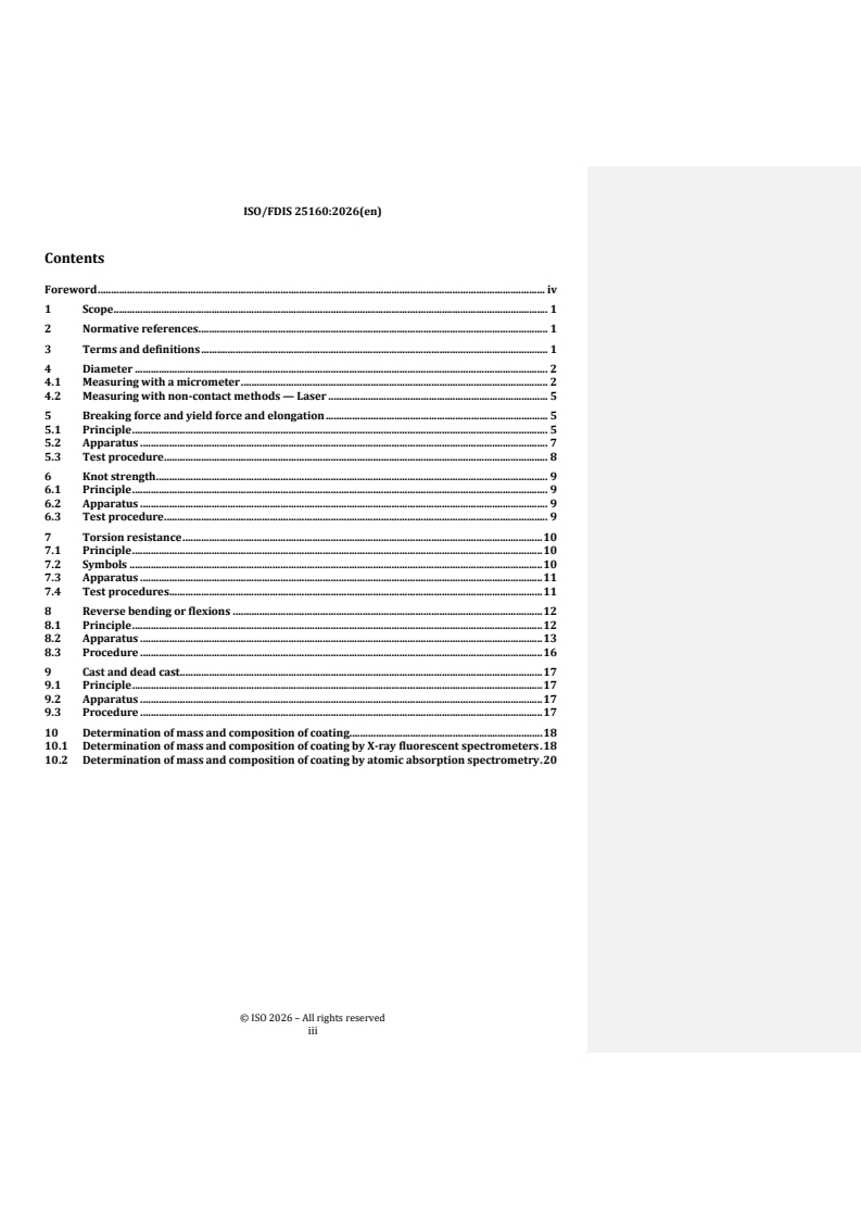
Contents Page
Foreword .v
1 Scope . 1
2 Normative references . 1
3 Terms and definitions . 1
4 Diameter . 2
4.1 Measuring with a micrometer .2
4.1.1 Principle .2
4.1.2 Apparatus .2
4.1.3 Test procedure.2
4.2 Measuring with non-contact methods — Laser .4
5 Breaking force and yield force and elongation . 4
5.1 Principle .4
5.2 Apparatus .5
5.2.1 Tensile testing machine .5
5.2.2 Grips.5
5.2.3 Extensometer .5
5.2.4 Oven .6
5.3 Test procedure .6
5.3.1 Sample preparation .6
5.3.2 Test settings.6
5.3.3 Test process .7
5.3.4 Calculation .7
5.3.5 Report.7
6 Knot strength . 7
6.1 Principle .7
6.2 Apparatus .7
6.3 Test procedure .7
6.3.1 Sample preparation .7
6.3.2 Test process .8
6.3.3 Calculation .8
6.3.4 Report.8
7 Torsion resistance . 8
7.1 Principle .8
7.2 Symbols .8
7.3 Apparatus .9
7.3.1 Torsion test machine .9
7.4 Test procedures .9
7.4.1 Sample preparation .9
7.4.2 Test process .9
7.4.3 Test report .10
8 Reverse bending or flexions . 10
8.1 Principle .10
8.2 Apparatus .11
8.3 Procedure . 13
8.3.1 Sample preparation . 13
8.3.2 Test process . 13
8.3.3 Test report . 13
9 Cast and dead cast . 14
9.1 Principle .14
9.2 Apparatus .14
9.3 Procedure .14
9.3.1 Cast .14
iii
9.3.2 Tip rise . .14
9.3.3 Test report .14
10 Determination of mass and composition of coating .15
10.1 Determination of mass and composition of coating by X-ray fluorescent spectrometers . 15
10.1.1 Principle . 15
10.1.2 Apparatus . 15
10.1.3 Reagents . 15
10.1.4 Preparation of test samples .16
10.1.5 Procedure .16
10.1.6 Expression of results .16
10.1.7 Test report .17
10.2 Determination of mass and composition of coating by atomic absorption spectrometry .17
10.2.1 Principle .17
10.2.2 Apparatus .17
10.2.3 Reagents .17
10.2.4 Procedure .18
10.2.5 Calculation .18
10.2.6 Test report .18
iv
Foreword
ISO (the International Organization for Standardization) is a worldwide federation of national standards
bodies (ISO member bodies). The work of preparing International Standards is normally carried out through
ISO technical committees. Each member body interested in a subject for which a technical committee
has been established has the right to be represented on that committee. International organizations,
governmental and non-governmental, in liaison with ISO, also take part in the work. ISO collaborates closely
with the International Electrotechnical Commission (IEC) on all matters of electrotechnical standardization.
The procedures used to develop this document and those intended for its further maintenance are described
in the ISO/IEC Directives, Part 1. In particular the different approval criteria needed for the different types
of ISO documents should be noted. This document was drafted in accordance with the editorial rules of the
ISO/IEC Directives, Part 2 (see www.iso.org/directives).
ISO draws attention to the possibility that the implementation of this document may involve the use of (a)
patent(s). ISO takes no position concerning the evidence, validity or applicability of any claimed patent
rights in respect thereof. As of the date of publication of this document, ISO had not received notice of (a)
patent(s) which may be required to implement this document. However, implementers are cautioned that
this may not represent the latest information, which may be obtained from the patent database available at
www.iso.org/patents. ISO shall not be held responsible for identifying any or all such patent rights.
Any trade name used in this document is information given for the convenience of users and does not
constitute an endorsement.
For an explanation of the voluntary nature of standards, the meaning of ISO specific terms and expressions
related to conformity assessment, as well as information about ISO's adherence to the World Trade
Organization (WTO) principles in the Technical Barriers to Trade (TBT), see www.iso.org/iso/foreword.html.
This document was prepared by Technical Committee ISO/TC 17, Steel, Subcommittee SC 17, Steel wire rod
and wire products.
Any feedback or questions on this document should be directed to the user’s national standards body. A
complete listing of these bodies can be found at www.iso.org/members.html.
v
FINAL DRAFT International Standard ISO/FDIS 25160:2026(en)
Testing method for hose reinforcement wire
1 Scope
This document specifies test methods of round steel hose reinforcement wire which are used for hose
reinforcement. Test methods on mechanical properties and chemical properties (coating analysis) are
included.
By agreement, these test methods can be applied to similar single filaments used for reinforcement of other
rubber products.
2 Normative references
The following documents are referred to in the text in such a way that some or all of their content constitutes
requirements of this document. For dated references, only the edition cited applies. For undated references,
the latest edition of the referenced document (including any amendments) applies.
ISO 7800:2012, Metallic materials — Wire — Simple torsion test
ISO 23717, Steel wire and wire products — Hose reinforcement wire
3 Terms and definitions
For the purposes of this document, the terms and definitions given in ISO 23717 and the following apply.
ISO and IEC maintain terminology databases for use in standardization at the following addresses:
— ISO Online browsing platform: available at https:// www .iso .org/ obp
— IEC Electropedia: available at https:// www .electropedia .org/
3.1
breaking force
force level (B ) at fracture, expressed in N
L
3.2
maximum force
F
m
highest force the test piece withstands, expressed in N
3.3
elongation
percent total elongation at break (A ) is the extension at break divided by the original specimen length
t
times 100
3.4
yield force
force level at 0,2 % permanent elongation offset, expressed in N
4 Diameter
4.1 Measuring with a micrometer
4.1.1 Principle
Hold a wire sample between two parallel circulars faced spindles of a micrometer. Close the movable spindle
gradually with controlled speed until it is in contact with the specimen. Read the value on the micrometer.
4.1.2 Apparatus
4.1.2.1 Micrometer
a) A precision cylindrical outside micrometer with non-rotating spindle type (see Figure 1).
b) In a laboratory setting, a digital precision micrometer with resolution of 0,001 mm shall be used.
c) Circular spindle Φ6,35 mm
d) Measuring range is from 0 mm to 25 mm.
e) Measuring force range: < 10 N.
Figure 1 — Cylindrical outside micrometer
4.1.3 Test procedure
4.1.3.1 Sample preparation
a) Cut a sample at length (about 10 cm to 15 cm).
b) A right-angle bend in the wire is to be applied to assist in rotating the wire between measurements.
c) The measured area of the wire shall be as straight as possible.
d) The wire surface shall be clean. Dirt and lubricant residues shall be removed with a clean tissue.
4.1.3.2 Zero-setting of the micrometer
a) Verify if the ‘display and nonius’ for digital micrometers and ‘nonius’ for analogue micrometers show
0,000 mm when the anvils are closed in a controlled way with 3 friction clicks.
b) When ‘reset action’ is needed; always first clean the anvil surface of the micrometer with clean paper
before the reset button is used.
c) This ‘zero-setting’ procedure needs to be done before each test series.
4.1.3.3 Methods of measuring
a) Method 1: Cylindrical outside micrometer: open and close method (see Figure 2).
Key
d the first reading, expressed in millimetres (mm)
d is the second reading, expressed in millimetres (mm)
d is the third reading, expressed in millimetres (mm)
d is the maximum diameter, expressed in millimetres (mm)
a
d is the minimum diameter, expressed in millimetres (mm)
b
Figure 2 — Diameter test diagrams
1) The movable anvil is closed until it is in contact with the specimen. The closing speed shall be controlled
until 3 clicks heard. The closing speed shall be controlled to avoid too high closing pressure and pressure
overshoots.
2) Measure value 1 and record as d .
3) Measure value 2 at 60° ± 10° rotation of the wire and record as d .
4) Measure value 3 at another 60° ± 10° rotating of the wire and record as d .
NOTE 1 Avoid measuring every 90° because after 2 rotations one is measuring at same angle again.
NOTE 2 When measuring method ‘out of roundness’ (ovality) is required.
5) Axially rotate the specimen between successive measurements to find maximum and minimum
diameter.
b) Method 2: Cylindrical outside micrometer: rotating method (see Figure 2).
1) The movable anvil is closed until it is in contact with the specimen and stay closed under a manually
applied stable closing force.
2) The sample is manually rotated 360° while the anvils are still in close position.
3) Maximum and minimum diameter is noted.
4) Average diameter is calculated out of Max and Min.
4.1.3.4 Calculations and report
4.1.3.4.1 M
...
ISO/TC 17/SC 17
Secretariat: SAC
Date: 2026-06-3008-21
Testing method for hose reinforcement wire
Méthode d'essai pour le fil de renforcement des tuyaux
FDIS stage
All rights reserved. Unless otherwise specified, or required in the context of its implementation, no part of this publication
may be reproduced or utilized otherwise in any form or by any means, electronic or mechanical, including photocopying,
or posting on the internet or an intranet, without prior written permission. Permission can be requested from either ISO
at the address below or ISO’s member body in the country of the requester.
ISO copyright office
CP 401 • Ch. de Blandonnet 8
CH-1214 Vernier, Geneva
Phone: + 41 22 749 01 11
EmailE-mail: copyright@iso.org
Website: www.iso.org
Published in Switzerland
ii
Contents
Foreword . iv
1 Scope . 1
2 Normative references . 1
3 Terms and definitions . 1
4 Diameter . 2
4.1 Measuring with a micrometer . 2
4.2 Measuring with non-contact methods — Laser . 5
5 Breaking force and yield force and elongation . 5
5.1 Principle . 5
5.2 Apparatus . 7
5.3 Test procedure . 8
6 Knot strength . 9
6.1 Principle . 9
6.2 Apparatus . 9
6.3 Test procedure . 9
7 Torsion resistance . 10
7.1 Principle . 10
7.2 Symbols . 10
7.3 Apparatus . 11
7.4 Test procedures . 11
8 Reverse bending or flexions . 12
8.1 Principle . 12
8.2 Apparatus . 13
8.3 Procedure . 16
9 Cast and dead cast . 17
9.1 Principle . 17
9.2 Apparatus . 17
9.3 Procedure . 17
10 Determination of mass and composition of coating . 18
10.1 Determination of mass and composition of coating by X-ray fluorescent spectrometers . 18
10.2 Determination of mass and composition of coating by atomic absorption spectrometry . 20
iii
Foreword
ISO (the International Organization for Standardization) is a worldwide federation of national standards
bodies (ISO member bodies). The work of preparing International Standards is normally carried out through
ISO technical committees. Each member body interested in a subject for which a technical committee has been
established has the right to be represented on that committee. International organizations, governmental and
non-governmental, in liaison with ISO, also take part in the work. ISO collaborates closely with the
International Electrotechnical Commission (IEC) on all matters of electrotechnical standardization.
The procedures used to develop this document and those intended for its further maintenance are described
in the ISO/IEC Directives, Part 1. In particular the different approval criteria needed for the different types of
ISO documents should be noted. This document was drafted in accordance with the editorial rules of the
ISO/IEC Directives, Part 2 (see www.iso.org/directives).
Field Code Changed
ISO draws attention to the possibility that the implementation of this document may involve the use of (a)
patent(s). ISO takes no position concerning the evidence, validity or applicability of any claimed patent rights
in respect thereof. As of the date of publication of this document, ISO had not received notice of (a) patent(s)
which may be required to implement this document. However, implementers are cautioned that this may not
represent the latest information, which may be obtained from the patent database available at
www.iso.org/patents. ISO shall not be held responsible for identifying any or all such patent rights.
Any trade name used in this document is information given for the convenience of users and does not
constitute an endorsement.
For an explanation of the voluntary nature of standards, the meaning of ISO specific terms and expressions
related to conformity assessment, as well as information about ISO's adherence to the World Trade
Organization (WTO) principles in the Technical Barriers to Trade (TBT), see www.iso.org/iso/foreword.html.
Field Code Changed
This document was prepared by Technical Committee ISO/TC 17, Steel, Subcommittee SC 17, Steel wire rod
and wire products.
Any feedback or questions on this document should be directed to the user’s national standards body. A
complete listing of these bodies can be found at www.iso.org/members.html.
iv
Testing method for hose reinforcement wire
1 Scope
This document specifies test methods of round steel hose reinforcement wire which are used for hose
reinforcement. Test methods on mechanical properties and chemical properties (coating analysis) are
included.
By agreement, these test methods maycan be applied to similar single filaments used for reinforcement of
other rubber products.
2 Normative references
The following documents are referred to in the text in such a way that some or all of their content constitutes
requirements of this document. For dated references, only the edition cited applies. For undated references,
the latest edition of the referenced document (including any amendments) applies.
ISO 7800:2012, Metallic materials — Wire — Simple torsion test
ISO 23717, Steel wire and wire products — Hose reinforcement wire
3 Terms and definitions
For the purposes of this document, the terms and definitions given in ISO 23717 and the following apply.
ISO and IEC maintain terminology databases for use in standardization at the following addresses:
— — ISO Online browsing platform: available at https://www.iso.org/obp
— — IEC Electropedia: available at https://www.electropedia.org/
3.1 3.1
breaking force
force level (BL) at fracture, expressed in N
3.2 3.2
maximum force
F
m
highest force the test piece withstands, expressed in N
3.3 3.3
elongation
percent total elongation at break (A ) is the extension at break divided by the original specimen length
t
times 100
3.4 3.4
yield force
force level at 0,2 % permanent elongation offset, expressed in N
4 Diameter
4.1 Measuring with a micrometer
4.1.1 Principle
Hold a wire sample between two parallel circulars faced spindles of a micrometer. Close the movable spindle
gradually with controlled speed until it is in contact with the specimen. Read the value on the micrometer.
4.1.2 Apparatus
4.1.2.1 Micrometer
a) a) A precision cylindrical outside micrometer with non-rotating spindle type (see
Figure 1Figure 1).).
b) b) In a laboratory setting, a digital precision micrometer with resolution of 0,001 mm shall be
used.
c) c) Circular spindle Φ6,35 mm
d) d) Measuring range is from 0 mm to 25 mm.
e) e) Measuring force range: < 10 N.
Figure 1 — Cylindrical outside micrometer
4.1.3 Test procedure
4.1.3.1 Sample preparation
a) a) Cut a sample at length (about 10 cm to 15 cm).
b) b) A right-angle bend in the wire is to be applied to assist in rotating the wire between
measurements.
c) c) The measured area of the wire shall be as straight as possible.
d) d) The wire surface shall be clean. Dirt and lubricant residues shall be removed with a clean tissue.
4.1.3.2 Zero-setting of the micrometer
a) a) Verify if the ‘display and nonius’ for digital micrometers and ‘nonius’ for analogue micrometers
show 0,000 mm when the anvils are closed in a controlled way with 3 friction clicks.
b) b) When ‘reset action’ is needed; always first clean the anvil surface of the micrometer with clean
paper before the reset button is used.
c) c) This ‘zero-setting’ procedure needs to be done before each test series.
4.1.3.3 Methods of measuring
a) a) Method 1: Cylindrical outside micrometer: open and close method (see Figure 2Figure 2).).
Key
d1 the first reading, expressed in millimetres (mm)
d is the second reading, expressed in millimetres (mm)
d is the third reading, expressed in millimetres (mm)
da is the maximum diameter, expressed in millimetres (mm)
db is the minimum diameter, expressed in millimetres (mm)
Figure 2 — Diameter test diagrams
1) 1) The movable anvil is closed until it is in contact with the specimen. The closing speed shall be
controlled until 3 clicks heard. The closing speed shall be controlled to avoid too high closing pressure
and pressure overshoots.
2) 2) Measure value 1 and record as d1.
3) 3) Measure value 2 at 60°+/-° ± 10° rotation of the wire and record as d .
4) 4) Measure value 3 at another 60°+/-° ± 10° rotating of the wire and record as d .
NOTE 1 Avoid measuring every 90° because after 2 rotations one is measuring at same angle again.
NOTE 2 When measuring method ‘out of roundness’ (ovality) is required.
5) 5) Axially rotate the specimen between successive measurements to find maximum and minimum
diameter.
6) b) Method 2: Cylindrical outside micrometer: rotating method (see Figure 2Figure 2).).
1) 1) The movable anvil is closed until it is in contact with the specimen and stay closed under a
manually applied stable closing force.
2) 2) The sample is manually rotated 360° while the anvils are still in close position.
3) 3) Maximum and minimum diameter is noted.
4) 4) Average diameter is calculated out of Max and Min.
4.1.3.4 Calculations and report
4.1.3.4.1 Method when no ovality or out of roundness is required
Determine the wire diameter by calculating the arithmetic mean of minimum 3 readings with
Formula (1)Formula (1).
d = ( d + d + d )/3 (1)
0 1 2 3
where
d is wire diameter
st
d is the 1 reading
nd
d is the 2 reading
rd
d is the 3 reading
d is the wire diameter;
st
d is the 1 reading;
nd
d2 is the 2 reading;
rd
d is the 3 reading.
4.1.3.4.2 Method when ovality or out of roundness is required
Determine the ‘Ovality’ by calculating the difference of the two readings with Formula (2)Formula (2):
Ov= da-db (2)
where
d = (d + d )/2 (3)
0 a b
da is the maximum diameter, expressed in millimetres (mm));
db is the minimum diameter, expressed in millimetres (mm));
d is the average diameter, expressed in millimetres (mm)).
4.2 Measuring with non-contact methods –— Laser
a) a) Resolution of 0,001 mm is minimum requirement.
b) b) Sample surface needs to be cleaned prior to test.
c) c) Sample needs to be perfect perpendicular positioned towards the laser beam.
d) d) Sample needs to be rotatable during testing having multiple measurements to calculate
average diameter or non-contact measuring devices shall be able to test in multiple angles (min 4) to take
average diameter.
5 Breaking force and yield force and elongation
5.1 Principle
This test method covers the measurement of breaking force, yield force, and elongation of single filament steel
reinforcement wire in a tensile test. Both ends of a test sample are clamped under a defined pretension in a
tensile testing machine; increasing load under a constant rate of extension is applied until the specimen
breaks. The change in force is measured versus the increase in separation of the specimen clamps to form a
force-extension curve. Breaking force (load) and maximum force and percent elongation at break and yield
force are measured or calculated (see Figure 3Figure 3).).
Key
F force
ep specified percentage plastic extension
0 zero point
mE slope of the elastic part of the stress-percentage extension curve
e percentage extension a fracture
F maximum force
m
At percentage total extension at fracture
Figure 3 — Tensile force - elongation curve
5.2 Apparatus
5.2.1 Tensile testing machine
a) a) Constant-Rate-of-Extension (CRE) tensile testing machine, its capacity shall ensure that the
measured force required to fracture the wire is within the calibrated range of the loadcell.
b) b) The capability of cross-head speed: ≥ 150 mm/min.
c) c) Machine accuracy Class 0,5 = Load weighing accuracy: +/-± 0,5 %
d) d) Load cell capacity depends on type and characteristics of the tested wire.
e) e) The structure of the machine and gripping systems shall be able to handle the axial force.
5.2.2 Grips
Grip types shall be selected according to the wire dimensions and wire characteristics and within the range of
the load cell. They can be wedge grips type, action screw type, or pneumatic action type with suitable jaw faces
(for example: smooth and ceramic or serrated jaw faces) to avoid failure of specimen at gripping point and
avoid slippage of specimen within the jaws.
5.2.3 Extensometer
a) a) Contact or no-contact extensometer.
b) b) Resolution of 0,001 % of the gauge length.
c) c) Standard clamp to clamp distance is 250 mm or 500 mm
Standard extensometer is 200 mm.
d) d) Extensometer accuracy Class 05.
— — Contact extensometer with sensor and contact arms
— — Non-contact extensometer
e) e) Video extensometer
f) f) Laser extensometer
g) g) Light extensometer
5.2.4 Oven
a) a) An oven is required only when testing at elevated temperature is specified.
b) b) The oven shall have a temperature capacity of at least 200 °C.
c) c) An oven with a built-in timer is recommended.
5.3 Test procedure
5.3.1 Sample preparation
a) a) Sample taking process shall avoid any undulations, loops, bends or damage of the wire and
wire surface.
b) b) Cut a piece of wire of the used test length plus twice the length of a jaw face.
c) c) When slippage occurs in the clamps, a new sample specimen shall be taken to retest.
d) d) When requested the wire can be thermally aged in an oven. Aging time and aging temperature
as agreed with requester. Standard aging conditions are: 60 min ± 1 min, at 150 °C ± 3 °C.
5.3.2 Test settings
a) Test length:
— — Standard gauge length Lo: = 500 mm
— — Standard extensometer gauge Le: = 200 mm
— — The gauge length Lo and Le can be adjusted according to the requester.
b) b) Speed:
— — Preload speed: 5 mm/min to 15 mm/min
— — Test speed @at 500 mm: 100 mm/min
— — Test speed @at 250 mm: 25 mm/min
— — Test speed with extensometer: 20 to 60 mm/min
c) c) Preload:
3 N for wires ≤ 0,50 mm
5 N or 10 N for wires > 0,50 mm;
d) d) The preload can be adjusted the wire is not taut at preload level.
— — General rule: The preload shall be as low as possible, but the wire shall be taut status between the
clamps, not slack.
e) e) The number of datapoints to construct the curve shall be at least 15001 500 datapoints.
5.3.3 Test process
a) a) Test carried out under controlled conditions shall be made at a temperature of 23 °C +/-± 5 °C.
b) b) Secure the specimen in the centre of the top clamp. Load the other end in the bottom clamp.
c) c) Manually apply a pretension just below the applied pre-load to take out any residual curvature
before initiating the test.
d) d) Start the machine and record force and extension of curve generated.
e) e) Run until specimen breaks.
f) f) When fracture location is closer than 3 mm from the grips then test cannot be validated.
g) g) Test is to discard, and new sample specimen is to test.
h) h) If these fractures close to clamps frequently occurs:
— — reduce clamping force but avoid slippage out of the clamps.
— — choose different jaw faces (for example: smooth and ceramic and light serrated jaw faces)
5.3.4 Calculation
Calculation of test parameters is done
...