

SIST EN 301 033 V1.3.1:2010
(Main)Electromagnetic compatibility and Radio spectrum Matters (ERM) - Technical characteristics and methods of measurement for shipborne watchkeeping receivers for reception of Digital Selective Calling (DSC) in the maritime MF, MF/HF and VHF bands
- Abstract
The present document states the minimum operational and performance requirements for shipborne receivers intended to be connected to an external installation, including a decoder for DSC, and used as receivers for watchkeeping DSC on board ships operating in the mobile MF, MF/HF and VHF band allocated in the ITU Radio Regulations [1] to the maritime mobile service, both in connection with distress and safety communication and in connection with general communication. These requirements include the relevant provisions of the ITU Radio Regulations [1], ITU-R Recommendations M.493-12 [3], M.541-9 [10], M.489-2 [9] and the IMO Resolutions A.803(19), A.804(19), A.806(19) and A.694(17). The present document specifies also technical characteristics, methods of testing and required test results for dedicated watchkeeping receivers for use with radio installations in the GMDSS as required by chapter IV of the SOLAS. It covers both receivers with analogue output or with digital DSC signal output interfaces or with both. DSC watchkeeping receivers may be a separate equipment or be integrated with a DSC or radiotelephone equipment. For integrated equipment the present document specifies the requirements and methods of testing of the DSC watchkeeping receivers only. DSC watchkeeping receivers can be either fixed-frequency receivers or, in MF/HF bands, scanning receivers. Requirements for the DSC equipment or radiotelephone equipment are given in EN 300 338-2 [12], EN 301 925 [11] and EN 300 373-1 [13] respectively.
- Status
- Published
- Publication Date
- 08-Nov-2010
- Technical Committee
- MOC - Mobile Communications
- Current Stage
- 6060 - National Implementation/Publication (Adopted Project)
- Start Date
- 22-Sep-2010
- Due Date
- 27-Nov-2010
- Completion Date
- 09-Nov-2010
Buy Documents
ETSI EN 301 033 V1.3.1 (2010-05) - Electromagnetic compatibility and Radio spectrum Matters (ERM); Technical characteristics and methods of measurement for shipborne watchkeeping receivers for reception of Digital Selective Calling (DSC) in the maritime MF, MF/HF and VHF bands
ETSI EN 301 033 V1.3.1 (2010-09) - Electromagnetic compatibility and Radio spectrum Matters (ERM); Technical characteristics and methods of measurement for shipborne watchkeeping receivers for reception of Digital Selective Calling (DSC) in the maritime MF, MF/HF and VHF bands

SIST EN 301 033 V1.3.1:2010 is the SIST adoption of the ETSI standard for shipborne watchkeeping receivers used for Digital Selective Calling (DSC) in the maritime MF, MF/HF and VHF bands. It specifies minimum operational and performance requirements, technical characteristics, test methods and required test results for receivers used on ships for distress, safety and general communication, including use in the Global Maritime Distress and Safety System (GMDSS).
What does SIST EN 301 033 V1.3.1:2010 specify?
SIST EN 301 033 V1.3.1:2010 specifies the requirements for shipborne DSC watchkeeping receivers that connect to an external installation and include a DSC decoder. The document covers separate receivers and the receiver part of integrated DSC or radiotelephone equipment.
The standard is organized into clauses on scope, references, definitions and abbreviations, general and operational requirements, technical requirements, test conditions, environmental tests, MF/HF performance, VHF performance, and radiated measurement arrangements.
| Annex | What it covers |
|---|---|
| Annex A | Normative radiated measurements, including outdoor and indoor test sites, antennas, substitution methods and anechoic chamber arrangements |
| Annex B | Informative bibliography |
What are the key requirements of SIST EN 301 033 V1.3.1:2010?
General design and operation
Clause 4 requires the equipment to maintain continuous watch on the relevant DSC channels and to be suitable for shipboard use and continuous operation. In practice, this means the receiver has to be ready for alarm and calling duties without frequent intervention.
Clause 4 also requires accessible construction, replaceable main modules, protection against static voltage at the antenna input, and software protection. The software and memory rules matter because distress calling information must remain available and operator-programmed memory needs protection against power interruption.
Clause 4.6 defines the interfaces for analogue and digital DSC outputs, and for scanning control and frequency read-out where provided. This is important for integration with external DSC decoder equipment and with ship systems using IEC 61162-1 or ITU-T V.11.
Bands, channels and reception modes
Clause 5 defines the operating bands and call channels. MF covers 1 606,5 kHz to 4 000 kHz, HF covers 4 MHz to 27,5 MHz, and VHF covers 156 MHz to 174 MHz.
For distress, urgency and safety calling, the standard fixes specific watch channels, including 2 187,5 kHz in MF and channel 70 at 156,525 MHz in VHF. MF/HF scanning receivers may scan up to 6 frequencies, and the document sets rules for which distress frequencies must be included when the operator can customize the scan list.
Clause 5 also fixes the reception classes: F1B or J2B for MF/HF DSC and G2B for VHF DSC. For a buyer or test lab, this tells you what demodulation mode the equipment must support.
Test conditions and performance
Clause 6 sets normal and extreme test conditions, signal connections, test frequencies, standard test signals and measurement uncertainty. It also requires bit error ratio measurements for digital outputs and for analogue outputs via a linear FSK discriminator.
Clauses 7 to 9 then apply environmental and RF performance checks. These include vibration, dry heat, damp heat, low temperature and corrosion, followed by calling sensitivity, adjacent channel selectivity, co-channel rejection, intermodulation, spurious response, dynamic range, spurious emissions, antenna input protection and scanning efficiency.
What terms does SIST EN 301 033 V1.3.1:2010 define?
- assigned frequency - the centre of the frequency band assigned to a station.
- continuous watch - a watch that is not interrupted except for brief breaks caused by the ship’s own communications or maintenance/checks.
- performance check - the receiver check of calling sensitivity described in clause 7.2.
- DSC (Digital Selective Calling) - the calling system used for maritime mobile service distress, safety and general calls.
- GMDSS (Global Maritime Distress and Safety System) - the ship radio framework that uses these receivers for distress and safety communications.
- MF/HF - Medium Frequency and High Frequency, the bands used for maritime DSC watchkeeping in this standard.
- VHF - Very High Frequency, used here for DSC watchkeeping on channel 70.
Who uses SIST EN 301 033 V1.3.1:2010?
The standard is used by manufacturers of shipborne DSC watchkeeping receivers, designers of integrated DSC and radiotelephone equipment, and test laboratories that verify conformance. It is also relevant to ship equipment integrators, marine radio installers, and quality or procurement teams that need to confirm the receiver supports the required maritime channels, interfaces and environmental performance.
Which standards are used with SIST EN 301 033 V1.3.1:2010?
- ITU Radio Regulations - define the maritime mobile service bands and channel framework used by the receiver.
- ITU-R Recommendation M.493-12 - defines the maritime DSC system the receiver must demodulate.
- ITU-R Recommendation M.541-9 - gives operational procedures for DSC use.
- ITU-R Recommendation M.489-2 - provides technical characteristics for VHF radiotelephone channels.
- ITU-T Recommendation E.161 - guides keypad digit arrangement.
- ITU-T Recommendation V.11 - defines compatible digital interface levels and stop/start control signals.
- IEC 61162-1 - provides the digital maritime interface used for frequency control and read-out.
- IEC 60417 - supplies graphical symbols for equipment markings.
- ETSI EN 300 338-2 - covers DSC equipment; this standard points to it for the DSC generator/decoder functions.
- ETSI EN 301 925 - covers VHF radiotelephone transmitters and receivers used with related equipment.
- ETSI EN 300 373-1 - covers maritime MF and HF transmitters and receivers.
What does the SIST EN 301 033 V1.3.1:2010 document contain?
The document contains detailed test methods for the receiver’s calling sensitivity, selectivity, rejection, dynamic range, emissions and protection against strong signals. It also defines environmental test procedures for vibration, temperature cycling and corrosion so the receiver can be assessed for shipboard service conditions.
Annex A gives the radiated measurement arrangements used for spurious emissions and receiver sensitivity measurements, including outdoor site geometry, antenna positioning and optional indoor anechoic chamber setups. Clause 6.9 also gives measurement uncertainty limits and how to interpret test results in a conformance report.
Buy Documents
ETSI EN 301 033 V1.3.1 (2010-05) - Electromagnetic compatibility and Radio spectrum Matters (ERM); Technical characteristics and methods of measurement for shipborne watchkeeping receivers for reception of Digital Selective Calling (DSC) in the maritime MF, MF/HF and VHF bands
ETSI EN 301 033 V1.3.1 (2010-09) - Electromagnetic compatibility and Radio spectrum Matters (ERM); Technical characteristics and methods of measurement for shipborne watchkeeping receivers for reception of Digital Selective Calling (DSC) in the maritime MF, MF/HF and VHF bands
Get Certified
Connect with accredited certification bodies for this standard

DNV
DNV is an independent assurance and risk management provider.

Lloyd's Register
Lloyd's Register is a global professional services organisation specialising in engineering and technology.

FSC International
Forest Stewardship Council certification.
Sponsored listings
Frequently Asked Questions
SIST EN 301 033 V1.3.1:2010 is a standard published by the Slovenian Institute for Standardization (SIST). Its full title is "Electromagnetic compatibility and Radio spectrum Matters (ERM) - Technical characteristics and methods of measurement for shipborne watchkeeping receivers for reception of Digital Selective Calling (DSC) in the maritime MF, MF/HF and VHF bands". This standard covers: The present document states the minimum operational and performance requirements for shipborne receivers intended to be connected to an external installation, including a decoder for DSC, and used as receivers for watchkeeping DSC on board ships operating in the mobile MF, MF/HF and VHF band allocated in the ITU Radio Regulations [1] to the maritime mobile service, both in connection with distress and safety communication and in connection with general communication. These requirements include the relevant provisions of the ITU Radio Regulations [1], ITU-R Recommendations M.493-12 [3], M.541-9 [10], M.489-2 [9] and the IMO Resolutions A.803(19), A.804(19), A.806(19) and A.694(17). The present document specifies also technical characteristics, methods of testing and required test results for dedicated watchkeeping receivers for use with radio installations in the GMDSS as required by chapter IV of the SOLAS. It covers both receivers with analogue output or with digital DSC signal output interfaces or with both. DSC watchkeeping receivers may be a separate equipment or be integrated with a DSC or radiotelephone equipment. For integrated equipment the present document specifies the requirements and methods of testing of the DSC watchkeeping receivers only. DSC watchkeeping receivers can be either fixed-frequency receivers or, in MF/HF bands, scanning receivers. Requirements for the DSC equipment or radiotelephone equipment are given in EN 300 338-2 [12], EN 301 925 [11] and EN 300 373-1 [13] respectively.
The present document states the minimum operational and performance requirements for shipborne receivers intended to be connected to an external installation, including a decoder for DSC, and used as receivers for watchkeeping DSC on board ships operating in the mobile MF, MF/HF and VHF band allocated in the ITU Radio Regulations [1] to the maritime mobile service, both in connection with distress and safety communication and in connection with general communication. These requirements include the relevant provisions of the ITU Radio Regulations [1], ITU-R Recommendations M.493-12 [3], M.541-9 [10], M.489-2 [9] and the IMO Resolutions A.803(19), A.804(19), A.806(19) and A.694(17). The present document specifies also technical characteristics, methods of testing and required test results for dedicated watchkeeping receivers for use with radio installations in the GMDSS as required by chapter IV of the SOLAS. It covers both receivers with analogue output or with digital DSC signal output interfaces or with both. DSC watchkeeping receivers may be a separate equipment or be integrated with a DSC or radiotelephone equipment. For integrated equipment the present document specifies the requirements and methods of testing of the DSC watchkeeping receivers only. DSC watchkeeping receivers can be either fixed-frequency receivers or, in MF/HF bands, scanning receivers. Requirements for the DSC equipment or radiotelephone equipment are given in EN 300 338-2 [12], EN 301 925 [11] and EN 300 373-1 [13] respectively.
SIST EN 301 033 V1.3.1:2010 is classified under the following ICS (International Classification for Standards) categories: 33.060.99 - Other equipment for radiocommunications; 33.100.01 - Electromagnetic compatibility in general; 47.020.70 - Navigation and control equipment. The ICS classification helps identify the subject area and facilitates finding related standards.
SIST EN 301 033 V1.3.1:2010 is available in PDF format for immediate download after purchase. The document can be added to your cart and obtained through the secure checkout process. Digital delivery ensures instant access to the complete standard document.
Standards Content (Sample)
Final draft ETSI EN 301 033 V1.3.1 (2010-05)
European Standard (Telecommunications series)
Electromagnetic compatibility
and Radio spectrum Matters (ERM);
Technical characteristics and methods of measurement
for shipborne watchkeeping receivers
for reception of Digital Selective Calling (DSC)
in the maritime MF, MF/HF and VHF bands
2 Final draft ETSI EN 301 033 V1.3.1 (2010-05)
Reference
REN/ERM-TG26-083
Keywords
DSC, maritime, radio, receiver
ETSI
650 Route des Lucioles
F-06921 Sophia Antipolis Cedex - FRANCE
Tel.: +33 4 92 94 42 00 Fax: +33 4 93 65 47 16
Siret N° 348 623 562 00017 - NAF 742 C
Association à but non lucratif enregistrée à la
Sous-Préfecture de Grasse (06) N° 7803/88
Important notice
Individual copies of the present document can be downloaded from:
http://www.etsi.org
The present document may be made available in more than one electronic version or in print. In any case of existing or
perceived difference in contents between such versions, the reference version is the Portable Document Format (PDF).
In case of dispute, the reference shall be the printing on ETSI printers of the PDF version kept on a specific network drive
within ETSI Secretariat.
Users of the present document should be aware that the document may be subject to revision or change of status.
Information on the current status of this and other ETSI documents is available at
http://portal.etsi.org/tb/status/status.asp
If you find errors in the present document, please send your comment to one of the following services:
http://portal.etsi.org/chaircor/ETSI_support.asp
Copyright Notification
No part may be reproduced except as authorized by written permission.
The copyright and the foregoing restriction extend to reproduction in all media.
© European Telecommunications Standards Institute 2010.
All rights reserved.
TM TM TM TM
DECT , PLUGTESTS , UMTS , TIPHON , the TIPHON logo and the ETSI logo are Trade Marks of ETSI registered
for the benefit of its Members.
TM
3GPP is a Trade Mark of ETSI registered for the benefit of its Members and of the 3GPP Organizational Partners.
LTE™ is a Trade Mark of ETSI currently being registered
for the benefit of its Members and of the 3GPP Organizational Partners.
GSM® and the GSM logo are Trade Marks registered and owned by the GSM Association.
ETSI
3 Final draft ETSI EN 301 033 V1.3.1 (2010-05)
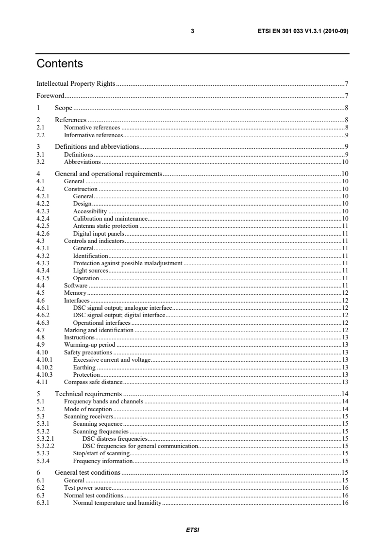
Contents
Intellectual Property Rights . 7
Foreword . 7
1 Scope . 8
2 References . 8
2.1 Normative references . 8
2.2 Informative references . 9
3 Definitions and abbreviations . 10
3.1 Definitions . 10
3.2 Abbreviations . 10
4 General and operational requirements . 10
4.1 General . 10
4.2 Construction . 10
4.2.1 General . 10
4.2.2 Design . 11
4.2.3 Accessibility . 11
4.2.4 Calibration and maintenance. 11
4.2.5 Antenna static protection . 11
4.2.6 Digital input panels . 11
4.3 Controls and indicators . 11
4.3.1 General . 11
4.3.2 Identification . 11
4.3.3 Protection against possible maladjustment . 11
4.3.4 Light sources . 12
4.3.5 Operation . 12
4.4 Software . 12
4.5 Memory . 12
4.6 Interfaces . 12
4.6.1 DSC signal output; analogue interface. 12
4.6.2 DSC signal output; digital interface . 12
4.6.3 Operational interfaces . 13
4.7 Marking and identification . 13
4.8 Instructions . 13
4.9 Warming-up period . 13
4.10 Safety precautions . 14
4.10.1 Excessive current and voltage . 14
4.10.2 Earthing . 14
4.10.3 Protection . 14
4.11 Compass safe distance . 14
5 Technical requirements . 14
5.1 Frequency bands and channels . 14
5.2 Mode of reception . 15
5.3 Scanning receivers . 15
5.3.1 Scanning sequence . 15
5.3.2 Scanning frequencies . 15
5.3.2.1 DSC distress frequencies . 15
5.3.2.2 DSC frequencies for general communication. 15
5.3.3 Stop/start of scanning. 15
5.3.4 Frequency information . 16
6 General test conditions . 16
6.1 General . 16
6.2 Test power source . 16
6.3 Normal test conditions . 16
6.3.1 Normal temperature and humidity . 16
ETSI
4 Final draft ETSI EN 301 033 V1.3.1 (2010-05)
6.3.2 Normal test power source . 16
6.3.2.1 ac voltage and frequency . 16
6.3.2.2 Secondary battery power sources . 17
6.3.2.3 Other power sources . 17
6.4 Extreme test conditions . 17
6.4.1 Extreme temperature tests . 17
6.4.2 Extreme values of test power source . 17
6.4.2.1 a.c. voltage and frequency . 17
6.4.2.2 Secondary battery power sources . 17
6.4.2.3 Other power sources . 17
6.5 Connection of test signals to the receiver . 17
6.5.1 Sources . 17
6.5.2 Levels . 18
6.6 Testing frequencies. 18
6.6.1 General test frequencies . 18
6.6.2 Additional test frequencies for HF equipment . 18
6.7 Test signals . 18
6.7.1 Standard test signal No. 1 . 18
6.7.2 Standard test signal No. 2 . 18
6.8 Measurement of bit error ratio . 18
6.9 Measurement uncertainty and interpretation of the measuring results . 19
6.9.1 Measurement uncertainty . 19
6.9.2 Interpretation of measurement results . 19
7 Environmental tests . 19
7.1 Procedure . 19
7.2 Performance check . 20
7.3 Vibration test . 20
7.3.1 Definition . 20
7.3.2 Method of measurement . 20
7.3.3 Requirement . 20
7.4 Temperature tests . 20
7.4.1 Dry heat . 21
7.4.1.1 Definition . 21
7.4.1.2 Method of measurement . 21
7.4.1.3 Requirement . 21
7.4.2 Damp heat . 21
7.4.2.1 Definition . 21
7.4.2.2 Method of measurement . 21
7.4.2.3 Requirement . 21
7.4.3 Low temperature . 21
7.4.3.1 Definition . 21
7.4.3.2 Method of measurement . 22
7.4.3.3 Requirement . 22
7.5 Corrosion test . 22
7.5.1 General . 22
7.5.2 Definition . 22
7.5.3 Method of measurement . 22
7.5.4 Requirements . 22
8 MF/HF watchkeeping receiver . 23
8.1 Calling sensitivity . 23
8.1.1 Definition . 23
8.1.2 Method of measurement . 23
8.1.3 Limits . 23
8.2 Adjacent channel selectivity . 23
8.2.1 Definition . 23
8.2.2 Method of measurement . 23
8.2.3 Limits . 24
8.3 Co-channel rejection. 24
8.3.1 Definition . 24
8.3.2 Method of measurements . 24
ETSI
5 Final draft ETSI EN 301 033 V1.3.1 (2010-05)
8.3.3 Limits . 24
8.4 RF intermodulation response . 24
8.4.1 Definition . 24
8.4.2 Method of measurement . 24
8.4.3 Limits . 24
8.5 Spurious response rejection . 25
8.5.1 Definition . 25
8.5.2 Method of measurement . 25
8.5.3 Limits . 26
8.6 Dynamic range . 26
8.6.1 Definition . 26
8.6.2 Method of measurement . 26
8.6.3 Limits . 26
8.7 Conducted spurious emissions into the antenna . 26
8.7.1 Definition . 26
8.7.2 Method of measurement . 26
8.7.3 Limits . 27
8.8 Radiated spurious emissions. 27
8.8.1 Definition . 27
8.8.2 Method of measurements . 27
8.8.3 Limit . 28
8.9 Protection of receiver antenna input circuits . 28
8.9.1 Definition . 28
8.9.2 Method of measurement . 28
8.9.3 Limits . 28
8.10 Scanning efficiency . 28
8.10.1 Definition . 28
8.10.2 Method of measurement . 28
8.10.3 Limits . 28
8.11 Stop/start of scanning (Watchkeeping receiver without DSC decoder) . 29
8.11.1 Definition . 29
8.11.2 Method of measurement . 29
8.11.3 Limits . 29
9 VHF watchkeeping receiver . 29
9.1 Calling sensitivity . 29
9.1.1 Definition . 29
9.1.2 Method of measurement . 29
9.1.3 Limits . 29
9.2 Adjacent channel selectivity . 29
9.2.1 Definition . 29
9.2.2 Method of measurement . 30
9.2.3 Limits . 30
9.3 Co-channel rejection. 30
9.3.1 Definition . 30
9.3.2 Method of measurement . 30
9.3.3 Limits . 30
9.4 Intermodulation response . 30
9.4.1 Definition . 30
9.4.2 Method of measurement . 31
9.4.3 Limits . 31
9.5 Spurious response and blocking immunity . 31
9.5.1 Definition . 31
9.5.2 Method of measurement . 31
9.5.3 Limits . 31
9.6 Dynamic range . 31
9.6.1 Definition . 31
9.6.2 Method of measurement . 32
9.6.3 Limit . 32
9.7 Conducted spurious emissions into the antenna . 32
9.7.1 Definition . 32
9.7.2 Method of measurement . 32
ETSI
6 Final draft ETSI EN 301 033 V1.3.1 (2010-05)
9.7.3 Limit . 32
9.8 Radiated spurious emissions. 32
9.8.1 Definition . 32
9.8.2 Method of measurements . 32
9.8.3 Limit . 33
Annex A (normative): Radiated measurements . 34
A.1 Test sites and general arrangements for measurements involving the use of radiated fields . 34
A.1.1 Outdoor test site . 34
A.1.2 Test antenna . 35
A.1.3 Substitution antenna . 35
A.1.4 Optional additional indoor site . 35
A.2 Guidance on the use of radiation test sites . 36
A.2.1 Measuring distance . 36
A.2.2 Test antenna . 36
A.2.3 Substitution antenna . 36
A.2.4 Artificial antenna . 37
A.2.5 Auxiliary cables . 37
A.2.6 Acoustic measuring arrangement . 37
A.3 Further optional alternative indoor test site using an anechoic chamber . 37
A.3.1 Example of the construction of a shielded anechoic chamber . 38
A.3.2 Influence of parasitic reflections in anechoic chambers . 38
A.3.3 Calibration of the shielded anechoic chamber . 39
Annex B (informative): Bibliography . 41
History . 42
ETSI
7 Final draft ETSI EN 301 033 V1.3.1 (2010-05)
Intellectual Property Rights
IPRs essential or potentially essential to the present document may have been declared to ETSI. The information
pertaining to these essential IPRs, if any, is publicly available for ETSI members and non-members, and can be found
in ETSI SR 000 314: "Intellectual Property Rights (IPRs); Essential, or potentially Essential, IPRs notified to ETSI in
respect of ETSI standards", which is available from the ETSI Secretariat. Latest updates are available on the ETSI Web
server (http://webapp.etsi.org/IPR/home.asp).
Pursuant to the ETSI IPR Policy, no investigation, including IPR searches, has been carried out by ETSI. No guarantee
can be given as to the existence of other IPRs not referenced in ETSI SR 000 314 (or the updates on the ETSI Web
server) which are, or may be, or may become, essential to the present document.
Foreword
This European Standard (Telecommunications series) has been produced by ETSI Technical Committee
Electromagnetic compatibility and Radio spectrum Matters (ERM), and is now submitted for the ETSI standards
One-step Approval Procedure.
Proposed national transposition dates
Date of latest announcement of this EN (doa): 3 months after ETSI publication
Date of latest publication of new National Standard
or endorsement of this EN (dop/e): 6 months after doa
Date of withdrawal of any conflicting National Standard (dow): 6 months after doa
ETSI
8 Final draft ETSI EN 301 033 V1.3.1 (2010-05)
1 Scope
The present document states the minimum operational and performance requirements for shipborne receivers intended
to be connected to an external installation, including a decoder for DSC, and used as receivers for watchkeeping DSC
on board ships operating in the mobile MF, MF/HF and VHF band allocated in the ITU Radio Regulations [1] to the
maritime mobile service, both in connection with distress and safety communication and in connection with general
communication.
These requirements include the relevant provisions of the ITU Radio Regulations [1], ITU-R Recommendations
M.493-12 [3], M.541-9 [10], M.489-2 [9] and the IMO Resolutions A.803(19), A.804(19), A.806(19) and A.694(17).
The present document specifies also technical characteristics, methods of testing and required test results for dedicated
watchkeeping receivers for use with radio installations in the GMDSS as required by chapter IV of the SOLAS.
It covers both receivers with analogue output or with digital DSC signal output interfaces or with both.
DSC watchkeeping receivers may be a separate equipment or be integrated with a DSC or radiotelephone equipment.
For integrated equipment the present document specifies the requirements and methods of testing of the DSC
watchkeeping receivers only.
DSC watchkeeping receivers can be either fixed-frequency receivers or, in MF/HF bands, scanning receivers.
Requirements for the DSC equipment or radiotelephone equipment are given in EN 300 338-2 [12], EN 301 925 [11]
and EN 300 373-1 [13] respectively.
2 References
References are either specific (identified by date of publication and/or edition number or version number) or
non-specific.
• For a specific reference, subsequent revisions do not apply.
• Non-specific reference may be made only to a complete document or a part thereof and only in the following
cases:
- if it is accepted that it will be possible to use all future changes of the referenced document for the
purposes of the referring document;
- for informative references.
Referenced documents which are not found to be publicly available in the expected location might be found at
http://docbox.etsi.org/Reference.
NOTE: While any hyperlinks included in this clause were valid at the time of publication ETSI cannot guarantee
their long term validity.
2.1 Normative references
The following referenced documents are indispensable for the application of the present document. For dated
references, only the edition cited applies. For non-specific references, the latest edition of the referenced document
(including any amendments) applies.
[1] ITU Radio Regulations (2008).
[2] ITU-T Recommendation E.161 (2001): "Arrangement of digits, letters and symbols on telephones
and other devices that can be used for gaining access to a telephone network".
[3] ITU-R Recommendation M.493-12 (2007): "Digital selective-calling system for use in the
maritime mobile service".
ETSI
9 Final draft ETSI EN 301 033 V1.3.1 (2010-05)
[4] ISO 3791 (1976): "Office machines and data processing equipment -- Keyboard layouts for
numeric applications".
[5] IEC 61162-1 (2007): "Maritime navigation and radiocommunication equipment and systems -
Digital interfaces - Part 1: Single talker and multiple listeners".
[6] Void.
[7] ITU-T Recommendation V.11 (1996): "Electrical characteristics for balanced double-current
interchange circuits operating at data signalling rates up to 10 Mbit/s".
[8] IEC 60417: "Graphical symbols for use on equipment".
[9] ITU-R Recommendation M.489-2: "Technical characteristics of VHF radiotelephone equipment
operating in the maritime mobile service in channels spaced by 25 kHz".
[10] ITU-R Recommendation M.541-9 (2004): "Operational procedures for the use of digital selective-
calling equipment in the maritime mobile service".
[11] ETSI EN 301 925: "Electromagnetic compatibility and Radio spectrum Matters (ERM);
Radiotelephone transmitters and receivers for the maritime mobile service operating in VHF
bands; Technical characteristics and methods of measurement".
[12] ETSI EN 300 338-2: "Electromagnetic compatibility and Radio spectrum Matters (ERM);
Technical characteristics and methods of measurement for equipment for generation, transmission
and reception of Digital Selective Calling (DSC) in the maritime MF, MF/HF and/or VHF mobile
service; Part 2: Class A/B DSC".
[13] ETSI EN 300 373-1: "Electromagnetic compatibility and Radio spectrum Matters (ERM);
Maritime mobile transmitters and receivers for use in the MF and HF bands; Part 1: Technical
characteristics and methods of measurement".
2.2 Informative references
The following referenced documents are not essential to the use of the present document but they assist the user with
regard to a particular subject area. For non-specific references, the latest version of the referenced document (including
any amendments) applies.
[i.1] Void.
[i.2] ITU-R Recommendation SM.332-4 (1978): "Selectivity of receivers".
[i.3] Void.
[i.4] Void.
[i.5] ETSI TR 100 028-1 (2001): "Electromagnetic compatibility and Radio spectrum Matters (ERM);
Uncertainties in the measurement of mobile radio equipment characteristics; Part 1".
ETSI
10 Final draft ETSI EN 301 033 V1.3.1 (2010-05)
3 Definitions and abbreviations
3.1 Definitions
For the purposes of the present document, the following terms and definitions apply:
assigned frequency: centre of the frequency band assigned to a station
continuous watch: continuous watch means that the radio watch concerned is not interrupted other than for brief
intervals when the ship's receiving capability is impaired or blocked by its own communications or when the facilities
are under periodical maintenance or check
F1B: frequency modulation with digital information, without a sub-carrier for automatic reception
G2B: phase-modulation with digital information, with a sub-carrier for automatic reception
J2B: single sideband with digital information, with the use of a modulating sub-carrier for automatic reception, with the
carrier suppressed to at least 40 dB below peak envelope power
performance check: check of calling sensitivity (see clause 7.2)
3.2 Abbreviations
For the purposes of the present document, the following abbreviations apply:
a.c. alternating current
d.c. direct current
DSC Digital Selective Calling
e.m.f. electromotive force
EUT Equipment Under Test
FSK Frequency Shift Keying
GMDSS Global Maritime Distress and Safety System
HF High Frequency
IF Intermediate Frequency
IMO International Maritime Organization
MF Medium Frequency
MF/HF Medium and High Frequency
r.m.s. root mean square
RF Radio Frequency
SOLAS (International Convention for the) Safety of Life at Sea
VHF Very High Frequency
4 General and operational requirements
4.1 General
The manufacturer shall declare that compliance to the requirement of clause 4 is achieved and shall provide relevant
documentation.
4.2 Construction
4.2.1 General
The equipment shall be so constructed that it is capable of keeping continuous watch on relevant DSC channels
(see clause 5.1) and of being operated readily.
ETSI
11 Final draft ETSI EN 301 033 V1.3.1 (2010-05)
4.2.2 Design
In all respects the mechanical and electrical design and construction and the finish of the equipment shall conform with
good engineering practice, and the equipment shall be suitable for use on board ships at sea.
The equipment shall be designed for continuous operation.
4.2.3 Accessibility
All parts of the equipment that are subject to inspection and maintenance adjustments, shall be easily accessible.
Components shall be easily identifiable either by markings within the equipment, or with the aid of technical
descriptions.
4.2.4 Calibration and maintenance
The equipment shall be so constructed that its main modules can easily be replaced and put into operation without
elaborate recalibration or readjustment.
4.2.5 Antenna static protection
In order to protect
...
European Standard (Telecommunications series)
Electromagnetic compatibility
and Radio spectrum Matters (ERM);
Technical characteristics and methods of measurement
for shipborne watchkeeping receivers
for reception of Digital Selective Calling (DSC)
in the maritime MF, MF/HF and VHF bands
2 ETSI EN 301 033 V1.3.1 (2010-09)
Reference
REN/ERM-TG26-083
Keywords
DSC, maritime, radio, receiver
ETSI
650 Route des Lucioles
F-06921 Sophia Antipolis Cedex - FRANCE
Tel.: +33 4 92 94 42 00 Fax: +33 4 93 65 47 16
Siret N° 348 623 562 00017 - NAF 742 C
Association à but non lucratif enregistrée à la
Sous-Préfecture de Grasse (06) N° 7803/88
Important notice
Individual copies of the present document can be downloaded from:
http://www.etsi.org
The present document may be made available in more than one electronic version or in print. In any case of existing or
perceived difference in contents between such versions, the reference version is the Portable Document Format (PDF).
In case of dispute, the reference shall be the printing on ETSI printers of the PDF version kept on a specific network drive
within ETSI Secretariat.
Users of the present document should be aware that the document may be subject to revision or change of status.
Information on the current status of this and other ETSI documents is available at
http://portal.etsi.org/tb/status/status.asp
If you find errors in the present document, please send your comment to one of the following services:
http://portal.etsi.org/chaircor/ETSI_support.asp
Copyright Notification
No part may be reproduced except as authorized by written permission.
The copyright and the foregoing restriction extend to reproduction in all media.
© European Telecommunications Standards Institute 2010.
All rights reserved.
TM TM TM TM
DECT , PLUGTESTS , UMTS , TIPHON , the TIPHON logo and the ETSI logo are Trade Marks of ETSI registered
for the benefit of its Members.
TM
3GPP is a Trade Mark of ETSI registered for the benefit of its Members and of the 3GPP Organizational Partners.
LTE™ is a Trade Mark of ETSI currently being registered
for the benefit of its Members and of the 3GPP Organizational Partners.
GSM® and the GSM logo are Trade Marks registered and owned by the GSM Association.
ETSI
3 ETSI EN 301 033 V1.3.1 (2010-09)
Contents
Intellectual Property Rights . 7
Foreword . 7
1 Scope . 8
2 References . 8
2.1 Normative references . 8
2.2 Informative references . 9
3 Definitions and abbreviations . 9
3.1 Definitions . 9
3.2 Abbreviations . 10
4 General and operational requirements . 10
4.1 General . 10
4.2 Construction . 10
4.2.1 General . 10
4.2.2 Design . 10
4.2.3 Accessibility . 10
4.2.4 Calibration and maintenance. 10
4.2.5 Antenna static protection . 11
4.2.6 Digital input panels . 11
4.3 Controls and indicators . 11
4.3.1 General . 11
4.3.2 Identification . 11
4.3.3 Protection against possible maladjustment . 11
4.3.4 Light sources . 11
4.3.5 Operation . 11
4.4 Software . 11
4.5 Memory . 12
4.6 Interfaces . 12
4.6.1 DSC signal output; analogue interface. 12
4.6.2 DSC signal output; digital interface . 12
4.6.3 Operational interfaces . 12
4.7 Marking and identification . 12
4.8 Instructions . 13
4.9 Warming-up period . 13
4.10 Safety precautions . 13
4.10.1 Excessive current and voltage . 13
4.10.2 Earthing . 13
4.10.3 Protection . 13
4.11 Compass safe distance . 13
5 Technical requirements . 14
5.1 Frequency bands and channels . 14
5.2 Mode of reception . 14
5.3 Scanning receivers . 15
5.3.1 Scanning sequence . 15
5.3.2 Scanning frequencies . 15
5.3.2.1 DSC distress frequencies . 15
5.3.2.2 DSC frequencies for general communication. 15
5.3.3 Stop/start of scanning. 15
5.3.4 Frequency information . 15
6 General test conditions . 15
6.1 General . 15
6.2 Test power source . 16
6.3 Normal test conditions . 16
6.3.1 Normal temperature and humidity . 16
ETSI
4 ETSI EN 301 033 V1.3.1 (2010-09)
6.3.2 Normal test power source . 16
6.3.2.1 ac voltage and frequency . 16
6.3.2.2 Secondary battery power sources . 16
6.3.2.3 Other power sources . 16
6.4 Extreme test conditions . 16
6.4.1 Extreme temperature tests . 16
6.4.2 Extreme values of test power source . 17
6.4.2.1 a.c. voltage and frequency . 17
6.4.2.2 Secondary battery power sources . 17
6.4.2.3 Other power sources . 17
6.5 Connection of test signals to the receiver . 17
6.5.1 Sources . 17
6.5.2 Levels . 17
6.6 Testing frequencies. 17
6.6.1 General test frequencies . 17
6.6.2 Additional test frequencies for HF equipment . 18
6.7 Test signals . 18
6.7.1 Standard test signal No. 1 . 18
6.7.2 Standard test signal No. 2 . 18
6.8 Measurement of bit error ratio . 18
6.9 Measurement uncertainty and interpretation of the measuring results . 19
6.9.1 Measurement uncertainty . 19
6.9.2 Interpretation of measurement results . 19
7 Environmental tests . 19
7.1 Procedure . 19
7.2 Performance check . 19
7.3 Vibration test . 20
7.3.1 Definition . 20
7.3.2 Method of measurement . 20
7.3.3 Requirement . 20
7.4 Temperature tests . 20
7.4.1 Dry heat . 21
7.4.1.1 Definition . 21
7.4.1.2 Method of measurement . 21
7.4.1.3 Requirement . 21
7.4.2 Damp heat . 21
7.4.2.1 Definition . 21
7.4.2.2 Method of measurement . 21
7.4.2.3 Requirement . 21
7.4.3 Low temperature . 21
7.4.3.1 Definition . 21
7.4.3.2 Method of measurement . 22
7.4.3.3 Requirement . 22
7.5 Corrosion test . 22
7.5.1 General . 22
7.5.2 Definition . 22
7.5.3 Method of measurement . 22
7.5.4 Requirements . 22
8 MF/HF watchkeeping receiver . 23
8.1 Calling sensitivity . 23
8.1.1 Definition . 23
8.1.2 Method of measurement . 23
8.1.3 Limits . 23
8.2 Adjacent channel selectivity . 23
8.2.1 Definition . 23
8.2.2 Method of measurement . 23
8.2.3 Limits . 24
8.3 Co-channel rejection. 24
8.3.1 Definition . 24
8.3.2 Method of measurements . 24
ETSI
5 ETSI EN 301 033 V1.3.1 (2010-09)
8.3.3 Limits . 24
8.4 RF intermodulation response . 24
8.4.1 Definition . 24
8.4.2 Method of measurement . 24
8.4.3 Limits . 24
8.5 Spurious response rejection . 25
8.5.1 Definition . 25
8.5.2 Method of measurement . 25
8.5.3 Limits . 26
8.6 Dynamic range . 26
8.6.1 Definition . 26
8.6.2 Method of measurement . 26
8.6.3 Limits . 26
8.7 Conducted spurious emissions into the antenna . 26
8.7.1 Definition . 26
8.7.2 Method of measurement . 26
8.7.3 Limits . 27
8.8 Radiated spurious emissions. 27
8.8.1 Definition . 27
8.8.2 Method of measurements . 27
8.8.3 Limit . 28
8.9 Protection of receiver antenna input circuits . 28
8.9.1 Definition . 28
8.9.2 Method of measurement . 28
8.9.3 Limits . 28
8.10 Scanning efficiency . 28
8.10.1 Definition . 28
8.10.2 Method of measurement . 28
8.10.3 Limits . 28
8.11 Stop/start of scanning (Watchkeeping receiver without DSC decoder) . 29
8.11.1 Definition . 29
8.11.2 Method of measurement . 29
8.11.3 Limits . 29
9 VHF watchkeeping receiver . 29
9.1 Calling sensitivity . 29
9.1.1 Definition . 29
9.1.2 Method of measurement . 29
9.1.3 Limits . 29
9.2 Adjacent channel selectivity . 29
9.2.1 Definition . 29
9.2.2 Method of measurement . 30
9.2.3 Limits . 30
9.3 Co-channel rejection. 30
9.3.1 Definition . 30
9.3.2 Method of measurement . 30
9.3.3 Limits . 30
9.4 Intermodulation response . 30
9.4.1 Definition . 30
9.4.2 Method of measurement . 31
9.4.3 Limits . 31
9.5 Spurious response and blocking immunity . 31
9.5.1 Definition . 31
9.5.2 Method of measurement . 31
9.5.3 Limits . 31
9.6 Dynamic range . 31
9.6.1 Definition . 31
9.6.2 Method of measurement . 32
9.6.3 Limit . 32
9.7 Conducted spurious emissions into the antenna . 32
9.7.1 Definition . 32
9.7.2 Method of measurement . 32
ETSI
6 ETSI EN 301 033 V1.3.1 (2010-09)
9.7.3 Limit . 32
9.8 Radiated spurious emissions. 32
9.8.1 Definition . 32
9.8.2 Method of measurements . 32
9.8.3 Limit . 33
Annex A (normative): Radiated measurements . 34
A.1 Test sites and general arrangements for measurements involving the use of radiated fields . 34
A.1.1 Outdoor test site . 34
A.1.2 Test antenna . 35
A.1.3 Substitution antenna . 35
A.1.4 Optional additional indoor site . 35
A.2 Guidance on the use of radiation test sites . 36
A.2.1 Measuring distance . 36
A.2.2 Test antenna . 36
A.2.3 Substitution antenna . 36
A.2.4 Artificial antenna . 37
A.2.5 Auxiliary cables . 37
A.2.6 Acoustic measuring arrangement . 37
A.3 Further optional alternative indoor test site using an anechoic chamber . 37
A.3.1 Example of the construction of a shielded anechoic chamber . 38
A.3.2 Influence of parasitic reflections in anechoic chambers . 38
A.3.3 Calibration of the shielded anechoic chamber . 39
Annex B (informative): Bibliography . 41
History . 42
ETSI
7 ETSI EN 301 033 V1.3.1 (2010-09)
Intellectual Property Rights
IPRs essential or potentially essential to the present document may have been declared to ETSI. The information
pertaining to these essential IPRs, if any, is publicly available for ETSI members and non-members, and can be found
in ETSI SR 000 314: "Intellectual Property Rights (IPRs); Essential, or potentially Essential, IPRs notified to ETSI in
respect of ETSI standards", which is available from the ETSI Secretariat. Latest updates are available on the ETSI Web
server (http://webapp.etsi.org/IPR/home.asp).
Pursuant to the ETSI IPR Policy, no investigation, including IPR searches, has been carried out by ETSI. No guarantee
can be given as to the existence of other IPRs not referenced in ETSI SR 000 314 (or the updates on the ETSI Web
server) which are, or may be, or may become, essential to the present document.
Foreword
This European Standard (Telecommunications series) has been produced by ETSI Technical Committee
Electromagnetic compatibility and Radio spectrum Matters (ERM).
National transposition dates
Date of adoption of this EN: 9 September 2010
Date of latest announcement of this EN (doa): 31 December 2010
Date of latest publication of new National Standard
or endorsement of this EN (dop/e): 30 June 2011
Date of withdrawal of any conflicting National Standard (dow): 30 June 2011
ETSI
8 ETSI EN 301 033 V1.3.1 (2010-09)
1 Scope
The present document states the minimum operational and performance requirements for shipborne receivers intended
to be connected to an external installation, including a decoder for DSC, and used as receivers for watchkeeping DSC
on board ships operating in the mobile MF, MF/HF and VHF band allocated in the ITU Radio Regulations [1] to the
maritime mobile service, both in connection with distress and safety communication and in connection with general
communication.
These requirements include the relevant provisions of the ITU Radio Regulations [1], ITU-R Recommendations
M.493-12 [3], M.541-9 [10], M.489-2 [9] and the IMO Resolutions A.803(19), A.804(19), A.806(19) and A.694(17).
The present document specifies also technical characteristics, methods of testing and required test results for dedicated
watchkeeping receivers for use with radio installations in the GMDSS as required by chapter IV of the SOLAS.
It covers both receivers with analogue output or with digital DSC signal output interfaces or with both.
DSC watchkeeping receivers may be a separate equipment or be integrated with a DSC or radiotelephone equipment.
For integrated equipment the present document specifies the requirements and methods of testing of the DSC
watchkeeping receivers only.
DSC watchkeeping receivers can be either fixed-frequency receivers or, in MF/HF bands, scanning receivers.
Requirements for the DSC equipment or radiotelephone equipment are given in EN 300 338-2 [12], EN 301 925 [11]
and EN 300 373-1 [13] respectively.
2 References
References are either specific (identified by date of publication and/or edition number or version number) or
non-specific. For specific references, only the cited version applies. For non-specific references, the latest version of the
reference document (including any amendments) applies.
Referenced documents which are not found to be publicly available in the expected location might be found at
http://docbox.etsi.org/Reference.
NOTE: While any hyperlinks included in this clause were valid at the time of publication ETSI cannot guarantee
their long term validity.
2.1 Normative references
The following referenced documents are necessary for the application of the present document.
[1] ITU Radio Regulations (2008).
[2] ITU-T Recommendation E.161 (2001): "Arrangement of digits, letters and symbols on telephones
and other devices that can be used for gaining access to a telephone network".
[3] ITU-R Recommendation M.493-12 (2007): "Digital selective-calling system for use in the
maritime mobile service".
[4] ISO 3791 (1976): "Office machines and data processing equipment -- Keyboard layouts for
numeric applications".
[5] IEC 61162-1 (2007): "Maritime navigation and radiocommunication equipment and systems -
Digital interfaces - Part 1: Single talker and multiple listeners".
[6] Void.
[7] ITU-T Recommendation V.11 (1996): "Electrical characteristics for balanced double-current
interchange circuits operating at data signalling rates up to 10 Mbit/s".
ETSI
9 ETSI EN 301 033 V1.3.1 (2010-09)
[8] IEC 60417: "Graphical symbols for use on equipment".
[9] ITU-R Recommendation M.489-2: "Technical characteristics of VHF radiotelephone equipment
operating in the maritime mobile service in channels spaced by 25 kHz".
[10] ITU-R Recommendation M.541-9 (2004): "Operational procedures for the use of digital selective-
calling equipment in the maritime mobile service".
[11] ETSI EN 301 925: "Electromagnetic compatibility and Radio spectrum Matters (ERM);
Radiotelephone transmitters and receivers for the maritime mobile service operating in VHF
bands; Technical characteristics and methods of measurement".
[12] ETSI EN 300 338-2: "Electromagnetic compatibility and Radio spectrum Matters (ERM);
Technical characteristics and methods of measurement for equipment for generation, transmission
and reception of Digital Selective Calling (DSC) in the maritime MF, MF/HF and/or VHF mobile
service; Part 2: Class A/B DSC".
[13] ETSI EN 300 373-1: "Electromagnetic compatibility and Radio spectrum Matters (ERM);
Maritime mobile transmitters and receivers for use in the MF and HF bands; Part 1: Technical
characteristics and methods of measurement".
2.2 Informative references
The following referenced documents are not necessary for the application of the present document but they assist the
user with regard to a particular subject area.
[i.1] Void.
[i.2] ITU-R Recommendation SM.332-4 (1978): "Selectivity of receivers".
[i.3] Void.
[i.4] Void.
[i.5] ETSI TR 100 028-1 (2001): "Electromagnetic compatibility and Radio spectrum Matters (ERM);
Uncertainties in the measurement of mobile radio equipment characteristics; Part 1".
3 Definitions and abbreviations
3.1 Definitions
For the purposes of the present document, the following terms and definitions apply:
assigned frequency: centre of the frequency band assigned to a station
continuous watch: continuous watch means that the radio watch concerned is not interrupted other than for brief
intervals when the ship's receiving capability is impaired or blocked by its own communications or when the facilities
are under periodical maintenance or check
F1B: frequency modulation with digital information, without a sub-carrier for automatic reception
G2B: phase-modulation with digital information, with a sub-carrier for automatic reception
J2B: single sideband with digital information, with the use of a modulating sub-carrier for automatic reception, with the
carrier suppressed to at least 40 dB below peak envelope power
performance check: check of calling sensitivity (see clause 7.2)
ETSI
10 ETSI EN 301 033 V1.3.1 (2010-09)
3.2 Abbreviations
For the purposes of the present document, the following abbreviations apply:
a.c. alternating current
d.c. direct current
DSC Digital Selective Calling
e.m.f. electromotive force
EUT Equipment Under Test
FSK Frequency Shift Keying
GMDSS Global Maritime Distress and Safety System
HF High Frequency
IF Intermediate Frequency
IMO International Maritime Organization
MF Medium Frequency
MF/HF Medium and High Frequency
r.m.s. root mean square
RF Radio Frequency
SOLAS (International Convention for the) Safety of Life at Sea
VHF Very High Frequency
4 General and operational requirements
4.1 General
The manufacturer shall declare that compliance to the requirement of clause 4 is achieved and shall provide relevant
documentation.
4.2 Construction
4.2.1 General
The equipment shall be so constructed that it is capable of keeping continuous watch on relevant DSC channels (see
clause 5.1) and of being operated readily.
4.2.2 Design
In all respects the mechanical and electrical design and construction and the finish of the equipment shall conform with
good engineering practice, and the equipment shall be suitable for use on board ships at sea.
The equipment shall be designed for continuous operation.
4.2.3 Accessibility
All parts of the equipment that are subject to inspection and maintenance adjustments, shall be easily accessible.
Components shall be easily identifiable either by markings within the equipment, or with the aid of technical
descriptions.
4.2.4 Calibration and maintenance
The equipment shall be so constructed that its main modules can easily be replaced and put into operation without
elaborate recalibration or readjustment.
ETSI
11 ETSI EN 301 033 V1.3.1 (2010-09)
4.2.5 Antenna static protection
In order to protect against damage due to static voltages that may appear at the input of the receiver, there shall be a d.c.
path from the antenna terminal to ground not exceeding 100 kΩ.
4.2.6 Digital input panels
Where a digital input panel with the digits "0" to "9" is provided, the digits should be arranged to conform with
ITU-T Recommendation E.161 [2]. However, where an alphanumeric keyboard layout, as used on office machinery and
data processing equipment, is provided, the digits "0" to "9" may, alternatively, be arranged to conform with
ISO 3791 [4].
4.3 Controls and indicators
4.3.1 General
The number of operational controls, their design an
...
2003-01.Slovenski inštitut za standardizacijo. Razmnoževanje celote ali delov tega standarda ni dovoljeno.9+)Electromagnetic compatibility and Radio spectrum Matters (ERM) - Technical characteristics and methods of measurement for shipborne watchkeeping receivers for reception of Digital Selective Calling (DSC) in the maritime MF, MF/HF and VHF bands47.020.70Navigacijska in krmilna opremaNavigation and control equipment33.100.01Elektromagnetna združljivost na splošnoElectromagnetic compatibility in general33.060.99Druga oprema za radijske komunikacijeOther equipment for radiocommunicationsICS:Ta slovenski standard je istoveten z:EN 301 033 Version 1.3.1SIST EN 301 033 V1.3.1:2010en01-december-2010SIST EN 301 033 V1.3.1:2010SLOVENSKI
STANDARD
ETSI ETSI EN 301 033 V1.3.1 (2010-09) 2
Reference REN/ERM-TG26-083 Keywords DSC, maritime, radio, receiver ETSI 650 Route des Lucioles F-06921 Sophia Antipolis Cedex - FRANCE
Tel.: +33 4 92 94 42 00
Fax: +33 4 93 65 47 16
Siret N° 348 623 562 00017 - NAF 742 C Association à but non lucratif enregistrée à la Sous-Préfecture de Grasse (06) N° 7803/88
Important notice Individual copies of the present document can be downloaded from: http://www.etsi.org The present document may be made available in more than one electronic version or in print. In any case of existing or perceived difference in contents between such versions, the reference version is the Portable Document Format (PDF). In case of dispute, the reference shall be the printing on ETSI printers of the PDF version kept on a specific network drive within ETSI Secretariat. Users of the present document should be aware that the document may be subject to revision or change of status. Information on the current status of this and other ETSI documents is available at http://portal.etsi.org/tb/status/status.asp If you find errors in the present document, please send your comment to one of the following services: http://portal.etsi.org/chaircor/ETSI_support.asp Copyright Notification No part may be reproduced except as authorized by written permission. The copyright and the foregoing restriction extend to reproduction in all media.
© European Telecommunications Standards Institute 2010. All rights reserved.
DECTTM, PLUGTESTSTM, UMTSTM, TIPHONTM, the TIPHON logo and the ETSI logo are Trade Marks of ETSI registered for the benefit of its Members. 3GPPTM is a Trade Mark of ETSI registered for the benefit of its Members and of the 3GPP Organizational Partners. LTE™ is a Trade Mark of ETSI currently being registered for the benefit of its Members and of the 3GPP Organizational Partners. GSM® and the GSM logo are Trade Marks registered and owned by the GSM Association. SIST EN 301 033 V1.3.1:2010
ETSI ETSI EN 301 033 V1.3.1 (2010-09) 3 Contents Intellectual Property Rights . 7 Foreword . 7 1 Scope . 8 2 References . 8 2.1 Normative references . 8 2.2 Informative references . 9 3 Definitions and abbreviations . 9 3.1 Definitions . 9 3.2 Abbreviations . 10 4 General and operational requirements . 10 4.1 General . 10 4.2 Construction . 10 4.2.1 General . 10 4.2.2 Design . 10 4.2.3 Accessibility . 10 4.2.4 Calibration and maintenance. 10 4.2.5 Antenna static protection . 11 4.2.6 Digital input panels . 11 4.3 Controls and indicators . 11 4.3.1 General . 11 4.3.2 Identification . 11 4.3.3 Protection against possible maladjustment . 11 4.3.4 Light sources . 11 4.3.5 Operation . 11 4.4 Software . 11 4.5 Memory . 12 4.6 Interfaces . 12 4.6.1 DSC signal output; analogue interface. 12 4.6.2 DSC signal output; digital interface . 12 4.6.3 Operational interfaces . 12 4.7 Marking and identification . 12 4.8 Instructions . 13 4.9 Warming-up period . 13 4.10 Safety precautions . 13 4.10.1 Excessive current and voltage . 13 4.10.2 Earthing . 13 4.10.3 Protection . 13 4.11 Compass safe distance . 13 5 Technical requirements . 14 5.1 Frequency bands and channels . 14 5.2 Mode of reception . 14 5.3 Scanning receivers . 15 5.3.1 Scanning sequence . 15 5.3.2 Scanning frequencies . 15 5.3.2.1 DSC distress frequencies . 15 5.3.2.2 DSC frequencies for general communication. 15 5.3.3 Stop/start of scanning. 15 5.3.4 Frequency information . 15 6 General test conditions . 15 6.1 General . 15 6.2 Test power source . 16 6.3 Normal test conditions . 16 6.3.1 Normal temperature and humidity . 16 SIST EN 301 033 V1.3.1:2010
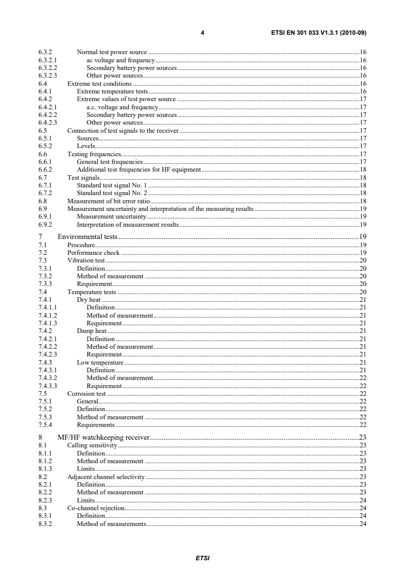
ETSI ETSI EN 301 033 V1.3.1 (2010-09) 4 6.3.2 Normal test power source . 16 6.3.2.1 ac voltage and frequency . 16 6.3.2.2 Secondary battery power sources . 16 6.3.2.3 Other power sources . 16 6.4 Extreme test conditions . 16 6.4.1 Extreme temperature tests . 16 6.4.2 Extreme values of test power source . 17 6.4.2.1 a.c. voltage and frequency . 17 6.4.2.2 Secondary battery power sources . 17 6.4.2.3 Other power sources . 17 6.5 Connection of test signals to the receiver . 17 6.5.1 Sources . 17 6.5.2 Levels . 17 6.6 Testing frequencies. 17 6.6.1 General test frequencies . 17 6.6.2 Additional test frequencies for HF equipment . 18 6.7 Test signals . 18 6.7.1 Standard test signal No. 1 . 18 6.7.2 Standard test signal No. 2 . 18 6.8 Measurement of bit error ratio . 18 6.9 Measurement uncertainty and interpretation of the measuring results . 19 6.9.1 Measurement uncertainty . 19 6.9.2 Interpretation of measurement results . 19 7 Environmental tests . 19 7.1 Procedure . 19 7.2 Performance check . 19 7.3 Vibration test . 20 7.3.1 Definition . 20 7.3.2 Method of measurement . 20 7.3.3 Requirement . 20 7.4 Temperature tests . 20 7.4.1 Dry heat . 21 7.4.1.1 Definition . 21 7.4.1.2 Method of measurement . 21 7.4.1.3 Requirement . 21 7.4.2 Damp heat . 21 7.4.2.1 Definition . 21 7.4.2.2 Method of measurement . 21 7.4.2.3 Requirement . 21 7.4.3 Low temperature . 21 7.4.3.1 Definition . 21 7.4.3.2 Method of measurement . 22 7.4.3.3 Requirement . 22 7.5 Corrosion test . 22 7.5.1 General . 22 7.5.2 Definition . 22 7.5.3 Method of measurement . 22 7.5.4 Requirements . 22 8 MF/HF watchkeeping receiver . 23 8.1 Calling sensitivity . 23 8.1.1 Definition . 23 8.1.2 Method of measurement . 23 8.1.3 Limits . 23 8.2 Adjacent channel selectivity . 23 8.2.1 Definition . 23 8.2.2 Method of measurement . 23 8.2.3 Limits . 24 8.3 Co-channel rejection. 24 8.3.1 Definition . 24 8.3.2 Method of measurements . 24 SIST EN 301 033 V1.3.1:2010
ETSI ETSI EN 301 033 V1.3.1 (2010-09) 5 8.3.3 Limits . 24 8.4 RF intermodulation response . 24 8.4.1 Definition . 24 8.4.2 Method of measurement . 24 8.4.3 Limits . 24 8.5 Spurious response rejection . 25 8.5.1 Definition . 25 8.5.2 Method of measurement . 25 8.5.3 Limits . 26 8.6 Dynamic range . 26 8.6.1 Definition . 26 8.6.2 Method of measurement . 26 8.6.3 Limits . 26 8.7 Conducted spurious emissions into the antenna . 26 8.7.1 Definition . 26 8.7.2 Method of measurement . 26 8.7.3 Limits . 27 8.8 Radiated spurious emissions. 27 8.8.1 Definition . 27 8.8.2 Method of measurements . 27 8.8.3 Limit . 28 8.9 Protection of receiver antenna input circuits . 28 8.9.1 Definition . 28 8.9.2 Method of measurement . 28 8.9.3 Limits . 28 8.10 Scanning efficiency . 28 8.10.1 Definition . 28 8.10.2 Method of measurement . 28 8.10.3 Limits . 28 8.11 Stop/start of scanning (Watchkeeping receiver without DSC decoder) . 29 8.11.1 Definition . 29 8.11.2 Method of measurement . 29 8.11.3 Limits . 29 9 VHF watchkeeping receiver . 29 9.1 Calling sensitivity . 29 9.1.1 Definition . 29 9.1.2 Method of measurement . 29 9.1.3 Limits . 29 9.2 Adjacent channel selectivity . 29 9.2.1 Definition . 29 9.2.2 Method of measurement . 30 9.2.3 Limits . 30 9.3 Co-channel rejection. 30 9.3.1 Definition . 30 9.3.2 Method of measurement . 30 9.3.3 Limits . 30 9.4 Intermodulation response . 30 9.4.1 Definition . 30 9.4.2 Method of measurement . 31 9.4.3 Limits . 31 9.5 Spurious response and blocking immunity . 31 9.5.1 Definition . 31 9.5.2 Method of measurement . 31 9.5.3 Limits . 31 9.6 Dynamic range . 31 9.6.1 Definition . 31 9.6.2 Method of measurement . 32 9.6.3 Limit . 32 9.7 Conducted spurious emissions into the antenna . 32 9.7.1 Definition . 32 9.7.2 Method of measurement . 32 SIST EN 301 033 V1.3.1:2010
ETSI ETSI EN 301 033 V1.3.1 (2010-09) 6 9.7.3 Limit . 32 9.8 Radiated spurious emissions. 32 9.8.1 Definition . 32 9.8.2 Method of measurements . 32 9.8.3 Limit . 33 Annex A (normative): Radiated measurements . 34 A.1 Test sites and general arrangements for measurements involving the use of radiated fields . 34 A.1.1 Outdoor test site . 34 A.1.2 Test antenna . 35 A.1.3 Substitution antenna . 35 A.1.4 Optional additional indoor site . 35 A.2 Guidance on the use of radiation test sites . 36 A.2.1 Measuring distance . 36 A.2.2 Test antenna . 36 A.2.3 Substitution antenna . 36 A.2.4 Artificial antenna . 37 A.2.5 Auxiliary cables . 37 A.2.6 Acoustic measuring arrangement . 37 A.3 Further optional alternative indoor test site using an anechoic chamber . 37 A.3.1 Example of the construction of a shielded anechoic chamber . 38 A.3.2 Influence of parasitic reflections in anechoic chambers . 38 A.3.3 Calibration of the shielded anechoic chamber . 39 Annex B (informative): Bibliography . 41 History . 42
ETSI ETSI EN 301 033 V1.3.1 (2010-09) 7 Intellectual Property Rights IPRs essential or potentially essential to the present document may have been declared to ETSI. The information pertaining to these essential IPRs, if any, is publicly available for ETSI members and non-members, and can be found in ETSI SR 000 314: "Intellectual Property Rights (IPRs); Essential, or potentially Essential, IPRs notified to ETSI in respect of ETSI standards", which is available from the ETSI Secretariat. Latest updates are available on the ETSI Web server (http://webapp.etsi.org/IPR/home.asp). Pursuant to the ETSI IPR Policy, no investigation, including IPR searches, has been carried out by ETSI. No guarantee can be given as to the existence of other IPRs not referenced in ETSI SR 000 314 (or the updates on the ETSI Web server) which are, or may be, or may become, essential to the present document. Foreword This European Standard (Telecommunications series) has been produced by ETSI Technical Committee Electromagnetic compatibility and Radio spectrum Matters (ERM).
National transposition dates Date of adoption of this EN: 9 September 2010 Date of latest announcement of this EN (doa): 31 December 2010 Date of latest publication of new National Standard or endorsement of this EN (dop/e):
30 June 2011 Date of withdrawal of any conflicting National Standard (dow): 30 June 2011
ETSI ETSI EN 301 033 V1.3.1 (2010-09) 8 1 Scope The present document states the minimum operational and performance requirements for shipborne receivers intended to be connected to an external installation, including a decoder for DSC, and used as receivers for watchkeeping DSC on board ships operating in the mobile MF, MF/HF and VHF band allocated in the ITU Radio Regulations [1] to the maritime mobile service, both in connection with distress and safety communication and in connection with general communication. These requirements include the relevant provisions of the ITU Radio Regulations [1], ITU-R Recommendations M.493-12 [3], M.541-9 [10], M.489-2 [9] and the IMO Resolutions A.803(19), A.804(19), A.806(19) and A.694(17). The present document specifies also technical characteristics, methods of testing and required test results for dedicated watchkeeping receivers for use with radio installations in the GMDSS as required by chapter IV of the SOLAS. It covers both receivers with analogue output or with digital DSC signal output interfaces or with both. DSC watchkeeping receivers may be a separate equipment or be integrated with a DSC or radiotelephone equipment. For integrated equipment the present document specifies the requirements and methods of testing of the DSC watchkeeping receivers only. DSC watchkeeping receivers can be either fixed-frequency receivers or, in MF/HF bands, scanning receivers. Requirements for the DSC equipment or radiotelephone equipment are given in EN 300 338-2 [12], EN 301 925 [11] and EN 300 373-1 [13] respectively. 2 References References are either specific (identified by date of publication and/or edition number or version number) or non-specific. For specific references, only the cited version applies. For non-specific references, the latest version of the reference document (including any amendments) applies. Referenced documents which are not found to be publicly available in the expected location might be found at http://docbox.etsi.org/Reference. NOTE: While any hyperlinks included in this clause were valid at the time of publication ETSI cannot guarantee their long term validity. 2.1 Normative references The following referenced documents are necessary for the application of the present document. [1] ITU Radio Regulations (2008). [2] ITU-T Recommendation E.161 (2001): "Arrangement of digits, letters and symbols on telephones and other devices that can be used for gaining access to a telephone network". [3] ITU-R Recommendation M.493-12 (2007): "Digital selective-calling system for use in the maritime mobile service". [4] ISO 3791 (1976): "Office machines and data processing equipment -- Keyboard layouts for numeric applications". [5] IEC 61162-1 (2007): "Maritime navigation and radiocommunication equipment and systems - Digital interfaces - Part 1: Single talker and multiple listeners". [6] Void. [7] ITU-T Recommendation V.11 (1996): "Electrical characteristics for balanced double-current interchange circuits operating at data signalling rates up to 10 Mbit/s". SIST EN 301 033 V1.3.1:2010
ETSI ETSI EN 301 033 V1.3.1 (2010-09) 9 [8] IEC 60417: "Graphical symbols for use on equipment". [9] ITU-R Recommendation M.489-2: "Technical characteristics of VHF radiotelephone equipment operating in the maritime mobile service in channels spaced by 25 kHz". [10] ITU-R Recommendation M.541-9 (2004): "Operational procedures for the use of digital selective-calling equipment in the maritime mobile service". [11] ETSI EN 301 925: "Electromagnetic compatibility and Radio spectrum Matters (ERM); Radiotelephone transmitters and receivers for the maritime mobile service operating in VHF bands; Technical characteristics and methods of measurement". [12] ETSI EN 300 338-2: "Electromagnetic compatibility and Radio spectrum Matters (ERM); Technical characteristics and methods of measurement for equipment for generation, transmission and reception of Digital Selective Calling (DSC) in the maritime MF, MF/HF and/or VHF mobile service; Part 2: Class A/B DSC". [13] ETSI EN 300 373-1: "Electromagnetic compatibility and Radio spectrum Matters (ERM); Maritime mobile transmitters and receivers for use in the MF and HF bands; Part 1: Technical characteristics and methods of measurement". 2.2 Informative references The following referenced documents are not necessary for the application of the present document but they assist the user with regard to a particular subject area. [i.1] Void. [i.2] ITU-R Recommendation SM.332-4 (1978): "Selectivity of receivers". [i.3] Void. [i.4] Void. [i.5] ETSI TR 100 028-1 (2001): "Electromagnetic compatibility and Radio spectrum Matters (ERM); Uncertainties in the measurement of mobile radio equipment characteristics; Part 1". 3 Definitions and abbreviations 3.1 Definitions For the purposes of the present document, the following terms and definitions apply: assigned frequency: centre of the frequency band assigned to a station continuous watch: continuous watch means that the radio watch concerned is not interrupted other than for brief intervals when the ship's receiving capability is impaired or blocked by its own communications or when the facilities are under periodical maintenance or check F1B: frequency modulation with digital information, without a sub-carrier for automatic reception G2B: phase-modulation with digital information, with a sub-carrier for automatic reception J2B: single sideband with digital information, with the use of a modulating sub-carrier for automatic reception, with the carrier suppressed to at least 40 dB below peak envelope power performance check: check of calling sensitivity (see clause 7.2) SIST EN 301 033 V1.3.1:2010
ETSI ETSI EN 301 033 V1.3.1 (2010-09) 10 3.2 Abbreviations For the purposes of the present document, the following abbreviations apply: a.c. alternating current d.c. direct current DSC Digital Selective Calling e.m.f. electromotive force EUT Equipment Under Test FSK Frequency Shift Keying GMDSS Global Maritime Distress and Safety System HF High Frequency IF Intermediate Frequency IMO International Maritime Organization MF Medium Frequency MF/HF Medium and High Frequency r.m.s. root mean square RF Radio Frequency SOLAS (International Convention for the) Safety of Life at Sea VHF Very High Frequency 4 General and operational requirements 4.1 General The manufacturer shall declare that compliance to the requirement of clause 4 is achieved and shall provide relevant documentation. 4.2 Construction 4.2.1 General The equipment shall be so constructed that it is capable of keeping continuous watch on relevant DSC channels (see clause 5.1) and of being operated readily. 4.2.2 Design In all respects the mechanical and electrical design and construction and the finish of the equipment shall conform with good engineering practice, and the equipment shall be suitable for use on board ships at sea. The equipment shall be designed for continuous operation. 4.2.3 Accessibility All parts of the equipment that are subject to inspection and maintenance adjustments, shall be easily accessible. Components shall be easily identifiable either by markings within the equipment, or with the aid of technical descriptions. 4.2.4 Calibration and maintenance The equipment shall be so constructed that its main modules can easily be replaced and put into operation without elaborate recalibration or readjustment. SIST EN 301 033 V1.3.1:2010
ETSI ETSI EN 301 033 V1.3.1 (2010-09) 11 4.2.5 Antenna static protection In order to protect against damage due to static voltages that may appear at the input of the receiver, there shall be a d.c. path from the antenna terminal to ground not exceeding 100 kΩ. 4.2.6 Digital input panels Where a digital input panel with the digits "0" to "9" is provided, the digits should be arranged to conform with ITU-T Recommendation E.161 [2]. However, where an alphanumeric keyboard layout, as used on office machinery and data processing equipment, is provided, the digits "0" to "9" may, alternatively, be arranged to conform with ISO 3791 [4].
...