

oSIST prEN 1538:2026
(Main)Execution of special geotechnical work - Diaphragm walls
- Abstract
This European Standard establishes general principles for the execution of diaphragm walls as either retaining walls or cut-off walls.
NOTE 1 This standard covers only structures constructed in a trench excavated with a support fluid or in dry conditions, where soil is removed and replaced by concrete or slurry and with wall thickness B ≥ 40 cm.
NOTE 2 Diaphragm walls can be permanent or temporary structures.
NOTE 3 The following types of structure are considered:
a) retaining walls: usually constructed to support the sides of an excavation in the ground. They include:
1) cast in situ concrete diaphragm walls;
2) precast concrete diaphragm walls;
3) reinforced slurry walls;
b) cut-off walls: usually constructed to prevent migration of groundwater, clear or polluted, or of other contaminants present in the ground. They include:
1) slurry walls (possibly with membranes or sheet piles);
2) plastic concrete walls.
NOTE 4 Walls formed shallow vertical trenches (typically excavations with a ratio of depth over thickness D/B < 5 or D < 5 m) are not covered by this standard.
- Status
- Not Published
- Public Enquiry End Date
- 19-Nov-2026
- Technical Committee
- KON - Structures
- Current Stage
- 4020 - Public enquire (PE) (Adopted Project)
- Start Date
- 05-Oct-2026
- Due Date
- 22-Feb-2027

oSIST prEN 1538:2026 is the Slovenian draft version of the European draft prEN 1538 from SIST/CEN. It specifies the execution of diaphragm walls for retaining walls, cut-off walls and barrettes, with requirements for planning, materials, execution, supervision, records and special requirements. It is written for engineers, contractors, supervisors, quality staff and buyers who need to define or check how special geotechnical works are carried out.
What does oSIST prEN 1538:2026 specify?
oSIST prEN 1538:2026 specifies general principles for executing diaphragm walls in trenches excavated with support fluid or in dry conditions, and for walls formed as retaining walls, cut-off walls or barrettes. It applies to permanent and temporary works and is intended to be used with the execution specifications for the project.
The document is organized into clauses on scope, normative references, terms and definitions, information needed for the work, geotechnical investigation, materials and products, design considerations, execution, supervision and inspection, records, and special requirements. It also includes three informative annexes that give guidance on watertightness, an example inspection and testing plan, and the degree of obligation used in the document.
| Annex | What it covers |
|---|---|
| Annex A | Watertightness guidance for embedded retaining walls |
| Annex B | Example inspection and testing plan for different diaphragm wall cases |
| Annex C | Degree of obligation used for the provisions |
What are the key requirements of oSIST prEN 1538:2026?
oSIST prEN 1538:2026 puts most of the control on the execution side: the project has to be planned from the site information, the ground investigation, the chosen execution method and the expected wall function. In practice, that means the document is not only about how to dig and pour, but also about what information has to be available before work starts and how the work is checked as it proceeds.
Execution specifications, site data and investigation
Clause 4 requires the execution specifications to gather the information needed for the work, including legal restrictions, site geometry, nearby structures and services, and a quality management system covering supervision, inspection, testing and monitoring. Clause 5 requires a geotechnical investigation that is sufficient for choosing the execution method and for recognizing risks such as obstructions, cavities, soft ground, groundwater conditions and soil or groundwater chemistry.
For a reader in practice, this means the wall cannot be planned only from the design intent. The contractor and designer need enough ground and site data to decide the method, tools, support fluid and sequence before excavation begins.
Materials, products and support fluids
Clause 6 requires the constituent materials to meet the relevant European Standards, the local provisions and the execution specifications, with documented sources of supply. It also sets specific expectations for bentonite, polymers, cement, aggregates, water, additions, admixtures, concrete, grout, plastic concrete, self-hardening slurry and reinforcement.
The same clause controls support fluids: they have to support the open trench during excavation and then allow concrete to displace them during concreting. For bentonite-based and polymer-based fluids, the document points to property checks and acceptance ranges, and it allows other fluid types only where full-scale trial trenches or comparable experience support their use. In practice, the team has to monitor fluid quality, not just deliver it.
Design considerations, watertightness and trench stability
Clause 7 says the design has to take the execution method into account, including tolerances, aggressive ground or groundwater and the practical stability of the trench. It also says diaphragm walls cannot be assumed to be fully watertight, so the design should specify a watertightness class based on the required performance and the site conditions.
For watertightness, the document uses classes from visible seepage to relatively dry performance. That matters because the wall function, joint type, recesses, concrete quality and surrounding conditions all affect what can realistically be achieved.
Clause 7 also requires trench stability to be checked by calculations, trial excavations or comparable experience, especially where support fluid is needed or where sudden fluid losses are possible. For socketing into rock or bearing strata, the design has to define the depth of penetration and the material quality to be reached. In practice, this is the point where the contractor has to confirm that the ground can actually be excavated and that the wall or barrette can reach its intended bearing or cut-off condition.
Reinforcement, cover and inserts
Clause 7.5 sets the design rules for reinforcement cages in reinforced concrete diaphragm walls. The cage has to be designed for handling, transport and installation, must preserve concrete flow, and has to leave space for tremie pipes, inserts, joints and cover control.
Clause 7.6 requires minimum and nominal cover to be based on EN 1992 and on execution tolerances. Spacers have to keep the cage in position without causing corrosion or cover damage, and the cage position has to allow the trench to be filled properly. For a buyer or quality manager, this is one of the main practical checks: the cage geometry must match the excavation and concreting method, not just the structural design.
Execution, concreting and quality control
Clause 8 requires a planned and approved execution plan before work starts, together with suitable working platforms and guide walls. It then controls excavation, cleaning of the trench, reinforcement installation, joints, concreting, grouting for barrettes and trimming to cut-off level.
The concreting rules are especially important. The document requires continuous monolithic placement, no internal vibration, control of concrete level and volume, and special care for submerged concreting with a tremie pipe. If the tremie immersion is lost, the document requires specific checks before work continues and documentation of any recovery method. In practice, this is the part that protects the wall from contamination, segregation and hidden defects.
Supervision, records and special requirements
Clause 9 requires supervision, inspection, testing and monitoring by qualified personnel, and it allows non-destructive testing to assess integrity. Clause 10 requires records as part of the Geotechnical Construction Record, including panel data, excavation data and concreting data. Clause 11 covers health, safety, environment and safe operation of the heavy equipment.
For the user, this means the standard is not satisfied by construction alone. The work has to be checked, recorded and traceable, because the wall is a geotechnical structure whose performance depends on execution quality.
What terms does oSIST prEN 1538:2026 define?
- execution specifications - the set of documents that bring together the technical requirements, drawings and other documents needed to execute the works.
- diaphragm wall - a wall built in a trench excavated in the ground.
- panel - a discrete length of diaphragm wall, or a connected group of lengths, formed and filled during excavation.
- retaining wall - a wall that supports the ground or additional loads, usually at an excavation.
- cut-off wall - a relatively thin barrier used to limit groundwater or contamination movement.
- barrette - a single panel used to transfer forces.
- support fluid - a bentonite, polymer or blended fluid used to support the trench sides.
- tremie pipe - a watertight concreting pipe used for submerged concrete placement.
Who uses oSIST prEN 1538:2026?
oSIST prEN 1538:2026 is used by geotechnical contractors, foundation specialists, site engineers, design engineers, supervisors and quality managers working on deep excavations and underground structures. It is also relevant to buyers and project teams writing execution specifications, because the document defines what information, materials, monitoring and records have to be included for diaphragm wall work. Its main industrial use is in special geotechnical works for retaining structures, groundwater cut-offs and foundation elements.
What changed in oSIST prEN 1538:2026 from the previous edition?
oSIST prEN 1538:2026 will supersede EN 1538:2010+A1:2015. The foreword states that it has been revised substantially in structure and content, and that it has been harmonized in particular to align with prEN 1536:2026.
Which standards are used with oSIST prEN 1538:2026?
| Standard | What it contributes |
|---|---|
| EN 206-1 | Concrete specification, performance, production and conformity |
| EN 206-3 | Additional concrete requirements for special geotechnical works |
| EN 1992 (all parts) | Design of concrete structures, including reinforcement and cover |
| EN 1993 (all parts) | Design of steel elements used in the wall |
| EN 1994 (all parts) | Design of composite steel and concrete elements |
| EN 1997 (all parts) | Geotechnical design framework and execution context |
| EN 10025-2 | Structural steel delivery conditions |
| EN 10080 | Reinforcing steel for concrete cages |
| EN 10210 (all parts) | Hot-finished structural hollow sections |
| EN 10219 (all parts) | Cold-formed welded structural hollow sections |
| EN 10248 (all parts) | Hot rolled sheet piling |
| EN 10249 (all parts) | Cold formed sheet piling |
| EN 12715 | Grouting rules where grout is used |
| EN 13670 | Execution of concrete structures and on-site concrete control |
| EN 16228 (all parts) | Safety for drilling and foundation equipment |
What does the oSIST prEN 1538:2026 document contain?
The document contains figures showing typical panel geometry, a barrette and the construction deviation terms used for tolerances. It also includes tables for support fluid characteristics, watertightness classification and an example inspection and testing plan for cast-in situ walls, precast elements, slurry cut-off walls and plastic concrete cut-off walls.
Annex A explains watertightness paths, design choices, joint effects and execution issues that influence water ingress. Annex B turns the requirements into practical inspection and testing points for site control, while Annex C explains how to read the document’s requirements, recommendations, permissions and statements.
Relations
- Effective Date
- 09-Jul-2024
Get Certified
Connect with accredited certification bodies for this standard

Zavod za gradbeništvo Slovenije (ZAG) - Inšpekcija
ZAG inspection body for construction products, structures, and materials.
Sponsored listings
Frequently Asked Questions
oSIST prEN 1538:2026 is a draft published by the Slovenian Institute for Standardization (SIST). Its full title is "Execution of special geotechnical work - Diaphragm walls". This standard covers: This European Standard establishes general principles for the execution of diaphragm walls as either retaining walls or cut-off walls. NOTE 1 This standard covers only structures constructed in a trench excavated with a support fluid or in dry conditions, where soil is removed and replaced by concrete or slurry and with wall thickness B ≥ 40 cm. NOTE 2 Diaphragm walls can be permanent or temporary structures. NOTE 3 The following types of structure are considered: a) retaining walls: usually constructed to support the sides of an excavation in the ground. They include: 1) cast in situ concrete diaphragm walls; 2) precast concrete diaphragm walls; 3) reinforced slurry walls; b) cut-off walls: usually constructed to prevent migration of groundwater, clear or polluted, or of other contaminants present in the ground. They include: 1) slurry walls (possibly with membranes or sheet piles); 2) plastic concrete walls. NOTE 4 Walls formed shallow vertical trenches (typically excavations with a ratio of depth over thickness D/B < 5 or D < 5 m) are not covered by this standard.
This European Standard establishes general principles for the execution of diaphragm walls as either retaining walls or cut-off walls. NOTE 1 This standard covers only structures constructed in a trench excavated with a support fluid or in dry conditions, where soil is removed and replaced by concrete or slurry and with wall thickness B ≥ 40 cm. NOTE 2 Diaphragm walls can be permanent or temporary structures. NOTE 3 The following types of structure are considered: a) retaining walls: usually constructed to support the sides of an excavation in the ground. They include: 1) cast in situ concrete diaphragm walls; 2) precast concrete diaphragm walls; 3) reinforced slurry walls; b) cut-off walls: usually constructed to prevent migration of groundwater, clear or polluted, or of other contaminants present in the ground. They include: 1) slurry walls (possibly with membranes or sheet piles); 2) plastic concrete walls. NOTE 4 Walls formed shallow vertical trenches (typically excavations with a ratio of depth over thickness D/B < 5 or D < 5 m) are not covered by this standard.
oSIST prEN 1538:2026 is classified under the following ICS (International Classification for Standards) categories: 93.020 - Earthworks. Excavations. Foundation construction. Underground works. The ICS classification helps identify the subject area and facilitates finding related standards.
oSIST prEN 1538:2026 has the following relationships with other standards: It is inter standard links to SIST EN 1538:2011+A1:2015. Understanding these relationships helps ensure you are using the most current and applicable version of the standard.
oSIST prEN 1538:2026 is available in PDF format for immediate download after purchase. The document can be added to your cart and obtained through the secure checkout process. Digital delivery ensures instant access to the complete standard document.
Standards Content (Sample)
SLOVENSKI STANDARD
01-november-2026
Izvedba posebnih geotehničnih del - Diafragme
Execution of special geotechnical work - Diaphragm walls
Ausführung von Arbeiten im Spezialtiefbau - Schlitzwände
Exécution des travaux géotechniques spéciaux - Parois moulées
Ta slovenski standard je istoveten z: prEN 1538
ICS:
93.020 Zemeljska dela. Izkopavanja. Earthworks. Excavations.
Gradnja temeljev. Dela pod Foundation construction.
zemljo Underground works
2003-01.Slovenski inštitut za standardizacijo. Razmnoževanje celote ali delov tega standarda ni dovoljeno.
DRAFT
EUROPEAN STANDARD
NORME EUROPÉENNE
EUROPÄISCHE NORM
September 2026
ICS Will supersede EN 1538:2010+A1:2015
English Version
Execution of special geotechnical work - Diaphragm walls
Exécution des travaux géotechniques spéciaux - Parois Ausführung von Arbeiten im Spezialtiefbau -
moulées Schlitzwände
This draft European Standard is submitted to CEN members for enquiry. It has been drawn up by the Technical Committee
CEN/TC 288.
If this draft becomes a European Standard, CEN members are bound to comply with the CEN/CENELEC Internal Regulations
which stipulate the conditions for giving this European Standard the status of a national standard without any alteration.
This draft European Standard was established by CEN in three official versions (English, French, German). A version in any other
language made by translation under the responsibility of a CEN member into its own language and notified to the CEN-CENELEC
Management Centre has the same status as the official versions.
CEN members are the national standards bodies of Austria, Belgium, Bulgaria, Croatia, Cyprus, Czech Republic, Denmark, Estonia,
Finland, France, Germany, Greece, Hungary, Iceland, Ireland, Italy, Latvia, Lithuania, Luxembourg, Malta, Netherlands, Norway,
Poland, Portugal, Republic of North Macedonia, Romania, Serbia, Slovakia, Slovenia, Spain, Sweden, Switzerland, Türkiye and
United Kingdom.
Recipients of this draft are invited to submit, with their comments, notification of any relevant patent rights of which they are
aware and to provide supporting documentation.
Warning : This document is not a European Standard. It is distributed for review and comments. It is subject to change without
notice and shall not be referred to as a European Standard.
EUROPEAN COMMITTEE FOR STANDARDIZATION
COMITÉ EUROPÉEN DE NORMALISATION
EUROPÄISCHES KOMITEE FÜR NORMUNG
CEN-CENELEC Management Centre: Rue de la Science 23, B-1040 Brussels
© 2026 CEN All rights of exploitation in any form and by any means reserved Ref. No. prEN 1538:2026 E
worldwide for CEN national Members.
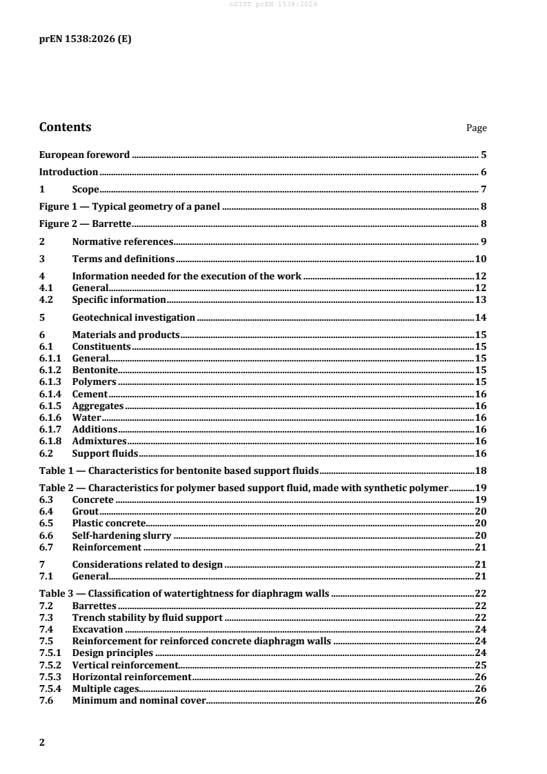
Contents Page
European foreword . 5
Introduction . 6
1 Scope . 7
Figure 1 — Typical geometry of a panel . 8
Figure 2 — Barrette . 8
2 Normative references . 9
3 Terms and definitions . 10
4 Information needed for the execution of the work . 12
4.1 General. 12
4.2 Specific information . 13
5 Geotechnical investigation . 14
6 Materials and products . 15
6.1 Constituents . 15
6.1.1 General. 15
6.1.2 Bentonite. 15
6.1.3 Polymers . 15
6.1.4 Cement . 16
6.1.5 Aggregates . 16
6.1.6 Water . 16
6.1.7 Additions . 16
6.1.8 Admixtures . 16
6.2 Support fluids . 16
Table 1 — Characteristics for bentonite based support fluids . 18
Table 2 — Characteristics for polymer based support fluid, made with synthetic polymer . 19
6.3 Concrete . 19
6.4 Grout . 20
6.5 Plastic concrete. 20
6.6 Self-hardening slurry . 20
6.7 Reinforcement . 21
7 Considerations related to design . 21
7.1 General. 21
Table 3 — Classification of watertightness for diaphragm walls . 22
7.2 Barrettes . 22
7.3 Trench stability by fluid support . 22
7.4 Excavation . 24
7.5 Reinforcement for reinforced concrete diaphragm walls . 24
7.5.1 Design principles . 24
7.5.2 Vertical reinforcement. 25
7.5.3 Horizontal reinforcement . 26
7.5.4 Multiple cages. 26
7.6 Minimum and nominal cover. 26
Figure 3 — Concrete cover and reinforcement bar spacing in diaphragm walls . 28
7.7 Precast concrete elements . 29
7.8 Profile elements . 29
7.9 Recesses . 29
8 Execution . 30
8.1 General . 30
8.2 Construction tolerances . 30
8.2.1 Geometrical tolerances of panels . 30
Figure 4 — Definition of geometrical construction deviation terms . 31
8.2.2 Installation tolerances for reinforcement cages . 32
8.2.3 Tolerances for trimming . 32
8.3 Preliminary works . 32
8.4 Excavation . 33
8.4.1 General . 33
8.4.2 Methods and tools . 34
8.4.3 Excavation sequence . 35
8.4.4 Unsupported trenches . 35
8.4.5 Trenches supported by support fluids. 35
8.5 Cleaning the trench . 36
8.6 Reinforcement . 36
8.6.1 General . 36
8.6.2 Coupling sections of reinforcement . 36
8.6.3 Spacers. 37
8.7 Joints between panels . 37
8.8 Concreting . 37
8.8.1 General . 37
8.8.2 Concreting in dry conditions . 38
8.8.3 Concreting in submerged conditions . 39
8.8.4 Loss of immersion of tremie pipe . 40
8.8.5 Precast concrete elements, steel tubes and profile elements . 41
8.9 External grouting of barrettes . 41
8.10 Trimming . 41
9 Supervision, inspection, testing and monitoring . 42
10 Records . 43
11 Special requirements . 43
Annex A (informative) Watertightness . 44
A.1 General . 44
A.2 Design Considerations impacting watertightness of retaining walls . 44
A.2.1 Principles . 44
Figure A.1 — Embedded retaining wall showing potential paths for groundwater ingress
through the wall . 45
A.2.2 Concrete . 45
A.2.3 Joints. 46
A.2.4 Testing and control of watertightness . 46
A.3 Execution . 46
A.3.1 Before Concreting . 46
A.3.2 Concreting Procedure . 47
A.3.3 Post-Concreting Considerations . 47
Annex B (informative) Example inspection and testing plan . 48
Table B.1 — Example inspection and testing plan for cast-in situ concrete diaphragm walls . 48
Table B.2 — Specific inspection and testing for precast concrete elements in diaphragm
walls or reinforced slurry walls . 52
Table B.3 — Specific inspection and testing for execution of slurry cut-off walls . 54
Table B.4 — Specific inspection and testing for execution of plastic concrete cut-off walls . 54
Annex C (informative) Degree of obligation of the provisions . 56
Bibliography . 57
European foreword
This document (prEN 1538:2026) has been prepared by Technical Committee CEN/TC 288 “Execution of
special geotechnical works”, the secretariat of which is held by AFNOR.
This document is currently submitted to the CEN Enquiry.
This document will supersede EN 1538:2010 + A1:2015.
This document includes the following significant technical changes with respect to EN 1538:2010 +
A1:2015:
— revised substantially in its structure and content;
— harmonized in particular to align with prEN 1536:2026.
This document has been prepared under a standardization request addressed to CEN by the European
Commission. The Standing Committee of the EFTA States subsequently approves these requests for its
Member States.
Introduction
Attention is drawn to the possibility that some of the elements of this document may be the subject of
patent rights. CEN shall not be held responsible for identifying any or all such patent rights.
The general scope of TC 288 is the standardisation of the execution procedures for geotechnical works,
including considerations to design, provisions on materials, supervision, testing and monitoring, records
of the works executed, and on special requirements including sustainability.
WG25 has been charged to revise EN 1538:2015, with the subject area of diaphragm walls, functioning
as retaining walls, cut-off walls, or as foundation elements (barrettes). Barrettes were dealt with
previously in prEN 1536:2026.
The design, planning and execution of diaphragm walls call for experience and knowledge in this
specialised field. The execution phase requires skilled and qualified personnel, and the present document
cannot replace the expertise of specialist contractors.
The document has been prepared to complement EN 1997, Eurocode 7: Geotechnical design. Clause 7
“Considerations related to design” of this document expands on design only where necessary (e.g. the
detailing of reinforcement) but shall provide full coverage of the execution and supervision requirements.
With regards to EN 13670, Execution of concrete structures, EN 1538 contains specific requirements for
diaphragm walls as a concrete structure, such as the detailing of the reinforcement, the concrete
placement and the supervision of concreting process which are complementing the provisions of
EN 13670.
Guidelines providing supplementary information, published by the European Federation of Foundation
Contractors and the Deep Foundation Institute, can be found in the bibliography. These are considered
to reflect state-of-the-art experience and contribute to a more elaborate understanding of the subject
matter.
1 Scope
1.1 This document establishes general principles for the execution of diaphragm walls and barrettes
as per the execution specifications.
NOTE 1 It is expected that the execution specifications define the execution standard to be applied based on
EN 1997 where relevant.
NOTE 2 Walls which deviate from the following clauses in this section can be considered as diaphragm walls
provided the execution principles correspond to this document (see Clause 8).
NOTE 3 The term diaphragm wall is used throughout this document and, where applicable, includes barrettes.
1.2 This document applies to diaphragm walls which may have various cross-sectional shapes, uniform
over depth (straight shaft), see Figure 1 and Figure 2.
1.3 This document applies to diaphragm walls with
— a wall thickness B ≥ 0,4 m,
— a depth to width ratio D/B ≥ 5, with D ≥ 5 m.
1.4 This document applies to permanent or temporary works for:
— retaining walls
— cut-off walls
— foundations (barrettes), usually formed by single panels or a combination of panels.
1.5 This document applies to diaphragm walls where excavation methods are either continuous or
discontinuous using support fluids for stabilizing the excavation walls where required.
1.6 This document applies only to execution methods that allow the designed cross-sections to be
produced.
1.7 This document applies to diaphragm walls constructed of:
— self-hardening slurries;
— unreinforced (plain) concrete incl. plastic concrete;
— reinforced concrete;
— concrete reinforced by structural elements (reinforcing elements);
— precast concrete (including prestressed concrete) elements or steel tubes where the gap between
the element or tube and the ground is filled by concrete or self-hardening slurry.
NOTE Concrete can be substituted by grout, where applicable.
Key
1 Wall thickness (B) 7 Guide-wall
2 Horizontal length of reinforcement cage 8 Cut off level
3 Cage width 9 Vertical length of reinforcement cage
4 Length of panel 10 Reinforcement cage
5 Working platform level 11 Depth of excavation (D)
6 concreting level 12 Concave portion of curved joints
Figure 1 — Typical geometry of a panel
Key
L Barrette length
B Barrette thickness
A Cross-sectional area of the shaft
Figure 2 — Barrette
2 Normative references
The following documents are referred to in the text in such a way that some or all of their content
constitutes requirements of this document. For dated references, only the edition cited applies. For
undated references, the latest edition of the referenced document (including any amendments) applies.
EN 206-1, Concrete - Specification, performance, production and conformity - Part 1: Performance,
requirements, factory production control and assessment criteria for individual values
EN 206-3, Concrete - Specification, performance, production and conformity - Part 3: Additional
requirements for specification and conformity of concrete for special geotechnical works
EN 1992 (all parts), Eurocode 2: Design of concrete structures
EN 1993 (all parts), Eurocode 3: Design of steel structures
EN 1994 (all parts), Eurocode 4: Design of composite steel and concrete structures
EN 1997 (all parts), Eurocode 7: Geotechnical design
EN 10025-2, Hot rolled products of structural steels - Part 2: Technical delivery conditions for non-alloy
structural steels
EN 10080, Steel for the reinforcement of concrete - Weldable reinforcing steel - General
EN 10210 (all parts), Hot finished structural hollow sections of non-alloy and fine grain steels
EN 10219 (all parts), Cold formed welded structural hollow sections of non-alloy and fine grain steels
EN 10248 (all parts), Hot rolled sheet piling of non alloy steels
EN 10249 (all parts), Cold formed sheet piling of non alloy steels
EN 12715, Execution of special geotechnical work - Grouting
EN 13670, Execution of concrete structures
EN 16228 (all parts), Drilling and foundation equipment – Safety
3 Terms and definitions
For the purposes of this document, the following terms and definitions apply.
ISO and IEC maintain terminology databases for use in standardization at the following addresses:
— ISO Online browsing platform: available at https://www.iso.org/obp/
— IEC Electropedia: available at https://www.electropedia.org/
3.1
execution specifications
set of documents covering all relevant requirements, technical specifications and construction drawings
necessary for the execution of the works
3.2
diaphragm wall
wall constructed in a trench excavated in the ground
3.3
panel
discrete length of diaphragm wall or a number of interconnecting lengths, formed by continuous or
discontinuous excavation methods and (simultaneously) filled with a self-hardening material (e.g. I-, L-,
T- or X-shape)
3.4
retaining wall
wall that provides lateral and/or vertical support to the ground or additional loads, usually to support
the sides of an excavation in the ground
3.5
cut-off wall
relatively thin barrier element used to prevent migration of groundwater or for confinement purposes
3.6
barrette
a single panel for the transfer of forces
3.7
base grouting
pressure injection of grout below the base of an installed barrette in order to enhance performance under
load
3.8
shaft grouting
injection of grout carried out after concrete of the barrette has set for the enhancement of skin friction
accomplished by the use of grouting pipes which are installed down the shaft, normally placed with the
barrette reinforcement
3.9
concreting level
upper level to which concrete is cast in a trench
3.10
cut-off level
designed level of the panel head
3.11
empty trench
length of excavation from the working platform level to the cut-off level
3.12
guide wall
a pair of shallow-depth, parallel temporary walls which used as a guide for the excavating tool, and to
secure the sides of the trench beneath the working platform level
3.13
support fluid
fluid consisting of bentonite or polymer or a combination of both used to support the sides of the
excavation
Note 1 to entry: A support fluid can also convey cuttings, e.g. in direct and reverse circulation operations.
3.14
self-hardening slurry
suspension consisting of binders with or without additions and admixtures which acts as a support fluid
during excavation and hardens with time
3.15
grout
pumpable material (suspension, solution or resins, emulsion or mortar respectively “sanded grout”)
which hardens with time
Note 1 to entry: Grout is typically used for injection but can also be a substitute for concrete.
3.16
plastic concrete
low-strength, low-stiffness and low-permeability concrete with high deformation capacity
3.17
concreting pipe
A section or sections of pipe generally made of steel, surmounted by a hopper or chute for concreting
under dry conditions
3.18
tremie pipe
concreting pipe, with watertight joints for submerged concrete placement
3.19
integrity test
test carried out on an installed panel to verify the soundness of materials and, depending on the method
used, the panel geometry
3.20
obstruction
a natural or artificial local anomaly generally requiring special tools or methods for its removal and or
penetration
3.21
spacer
spacer pad
component of plastic or steel material or concrete (pad) fixed to the reinforcement cage to maintain the
predetermined gap width, usually the concrete cover
3.22
stop-end
special formwork element to shape the vertical end of a panel and create a definite joint for the adjacent
panel
3.23
waterstop
special flexible element attached longitudinally to a stop-end in such a way that part of the waterstop is
embedded in concrete in a panel after the concreting and stop-end extracting operations
3.24
filter cake
formation of retained material such as bentonite and excavated soil from a suspension built up on the
face of a permeable medium by water drainage due to a pressure differential
3.25
trimming
removal of excess concrete above the designed cut-off level
3.26
excavation curve
diagram representing the excavation depth versus time
3.27
concreting curve
diagram representing the volume of poured concrete versus depth
4 Information needed for the execution of the work
4.1 General
4.1.1 Prior to the execution of the work, all necessary information shall be provided in the execution
specifications.
NOTE It is expected that the information includes technical requirements resulting from the function of the
diaphragm wall.
4.1.2 This information should include:
— any legal or statutory restrictions;
— the location of main grid lines for setting out;
— the conditions of structures, roads, services, etc. adjacent to the work, including any necessary
surveys;
— a suitable quality management system, including supervision, inspection, testing and monitoring and
maintenance in accordance with EN 1997-1:2024, Clause 10 and Clause 11.
NOTE Clause 9 of this document refers to supervision, inspection, testing, monitoring during execution.
4.1.3 The information regarding the site conditions shall cover, where relevant:
— the geometry of the site (boundary conditions, topography, access, slopes, headroom restrictions,
etc.);
— the existing underground structures, services, known contaminations, and archeological constraints;
— the environmental restrictions, including noise, vibration, pollution;
— the future or ongoing activities such as dewatering, tunnelling, deep excavations.
4.2 Specific information
4.2.1 The execution specifications shall include specific information.
4.2.2 The specific information shall include geotechnical information and data as specified in Clause 5.
NOTE Different from the reason for design of geotechnical structures, for execution the average ground
properties and their distribution are relevant to choose suitable work methods.
4.2.3 The specific information shall cover, where relevant:
— execution specifications;
— previous use of the site;
— adjacent foundations (types, loads and geometry);
— presence of obstructions in the ground (old masonry, anchors, etc.);
— presence of headroom restrictions;
— presence of archeological remains;
— presence of natural and/or man made cavities (mines, etc.);
— presence of contaminated ground, and type, extent and degree of contamination;
— any specific requirements for the diaphragm wall, in particular those pertaining to tolerances, quality
of materials, class of watertightness;
— where available, previous experience with diaphragm walls or underground works on or adjacent to
the site;
— for cut-off walls, permeability, strength and deformation properties of the wall material;
— proposed adjacent enabling or advance works such as underpinning, pre-treatment of soil,
dewatering that may affect the execution of a diaphragm wall ;
— functional requirements for instrumentation and monitoring of potentially affected structures;
4.2.4 Necessity, extent, procedure and content for any survey of the conditions of structures, roads,
utilities, etc. adjacent to the works area, during execution, shall be specified.
4.2.5 Required site survey shall be carried out and be available prior to the commencement of the
works.
NOTE The results are useful to define the threshold values for any movement which might affect adjacent
structures.
5 Geotechnical investigation
5.1 The geotechnical investigation shall provide all necessary information for the execution of the
works
NOTE The scope of the geotechnical investigation can exceed that is required in EN 1997 for the design of
geotechnical structures.
5.2 Relevant experience of the execution of comparable foundation works under similar conditions in
the vicinity of the site should be taken into account.
5.3 The geotechnical investigation report shall be available in time for the planning of the execution of
the diaphragm walls (e.g. the choice of method of execution).
5.4 The geotechnical investigation shall be checked to see whether it is sufficient for the execution of
the diaphragm walls.
5.5 If the geotechnical investigations are not sufficient, a supplementary investigation shall be
conducted.
5.6 The geotechnical investigation report shall include specific information regarding the following
aspects where relevant:
— the ground level at any point of investigation or testing relative to the recognised national datum or
to a fixed reference chart datum;
— ground properties necessary to determine work method, equipment and tools, and to estimate
performance as well as wear and tear, e.g. strength, density, abrasivity.
— piezometric levels and expected variation of all water-tables and permeability of the soils;
— presence of coarse, highly permeable soils or cavities (natural or artificial), to rate the risk of sudden
losses of support fluid.
— high ground-water velocities in underground strata which can cause difficulties during execution;
— presence, strength and deformation characteristics of soft soils, such as very soft clay or peat
— presence of boulders or obstructions which can cause difficulties during excavation and, an
assessment of their size and frequency, when applicable;
— presence, position, level in both the longitudinal and transverse direction, strength and degree of
weathering and the extent and direction of fissuring, strength of hard rock or other hard materials
which can cause difficulties during excavation and may require the use of special tools;
— chemistry of groundwater, soil and rock, and water temperatures if required;
— chemistry of waste materials;
— presence of pretreated soil, which can have an adverse effect during excavation;
— mining beneath the site;
— site stability problems (slope stability for instance).
6 Materials and products
6.1 Constituents
6.1.1 General
6.1.1.1 The constituents shall meet the requirements set in the respective European Standards, the
provisions valid in the place of use and the provisions given in the executions specifications.
6.1.1.2 The sources of supply of constituents shall be documented and shall not be changed without
prior notification.
6.1.2 Bentonite
6.1.2.1 In absence of a specific European Standard for bentonite for the application in geotechnical
works, a suitable production quality system shall be in place to prove consistency in production and each
delivery shall come with a conformity certificate.
NOTE Bentonite is a clay containing mainly the mineral montmorillonite and is used in support fluids, either
as pure bentonite suspension or as an addition to polymer solutions. It is also used as a constituent part of hardening
slurries and of plastic concrete.
6.1.2.2 Bentonite used in bentonite suspensions shall not contain harmful constituents in such
quantities as can be detrimental to reinforcement or concrete.
6.1.2.3 The chemical and mineralogical composition of the bentonite shall be supplied.
6.1.2.4 Representative data on characteristic technical parameters shall be supplied, proving
suitability for the field of application at a minimum:
— moisture content,
— percentage by mass of grain size greater than 0,063 mm,
— Marsh viscosity of a suspension with a given composition, and
— fluid loss of a suspension with a given composition.
NOTE 0,063 mm can be substituted by 0,074 mm where the quality system refers to imperial units
6.1.3 Polymers
6.1.3.1 In absence of a specific European Standard for polymers for the application in geotechnical
works, a suitable production quality system shall be in place to prove consistency in production and each
delivery shall come with a conformity certificate.
NOTE Polymers are materials formed of molecules from chained monomeric units and are used in support
fluids as pure polymer solution, or as additives to enhance rheological effectiveness of bentonite suspensions.
6.1.3.2 Polymers used in polymer solutions shall not contain harmful constituents in such quantities
as can be detrimental to reinforcement or concrete.
6.1.3.3 The generic classification of the polymers shall be noted in the product declaration.
NOTE Typically, polymers are classified either natural, synthetic or natural-modified.
6.1.3.4 Representative data on characteristic technical parameters shall be supplied, proving
suitability for the field of application, at a minimum:
— molecular weight,
— ionicity and charge density,
— type of polymer, and
— Marsh viscosity development curve for 24 h of a solution with a given composition.
6.1.4 Cement
6.1.4.1 Cement for concrete for diaphragm walls shall comply with EN 206-1 and EN 206-3.
6.1.4.2 Cement for self-hardening slurries or grout shall conform to the provisions valid in the place
of use and shall have established suitability for use in the specific application.
NOTE In accordance with EN 206-3, cementitious compounds can be used, or cement can be substituted by
additions.
6.1.5 Aggregates
Aggregates shall comply with EN 206-1 and EN 206-3.
6.1.6 Water
6.1.6.1 Mixing water for concrete shall comply with EN 206-1 and EN 206-3.
6.1.6.2 The suitability of mixing water for support fluid shall be proven by testing or by comparable
experience.
NOTE Testing is usually not necessary for tap / potable water.
6.1.7 Additions
The use of additions shall comply with EN 206-1 and EN 206-3.
6.1.8 Admixtures
Admixtures shall comply with EN 206-1 and EN 206-3.
6.2 Support fluids
6.2.1 For the design of support fluids the presence of hydraulic binders which may result from
preparatory and/or additional work (e.g. injection, jet-grouting) or from operating modes (e.g.
production of a joint by biting into an existent panel), and possible effects of temperature and chemical
components of the soil and groundwater should be taken into account.
6.2.2 A support fluid shall be prepared with either bentonite, polymers or a blend of bentonite and
polymers.
NOTE Additives can be necessary to adjust properties of the support fluid.
6.2.3 In certain cases, e.g. when the density of the support fluid has to be increased, suitable inert
materials may be added.
6.2.4 During excavation, the support fluid shall have and maintain properties required to support the
open excavation.
6.2.5 Before concreting, the support fluid shall have properties to allow its displacement by the
concrete.
6.2.6 Bentonite based support fluids should comply with requirements as set out in Table 1.
NOTE 1 Other properties can be specified in special circumstances, for example in:
— soils or rock with high permeability or cavities where loss of bentonite can occur;
— high piezometric ground water levels (confined or artesian conditions);
— very loose sand or soft soils (typically with q < 300 kPa or C < 15 kPa);
c u
— salt water conditions.
NOTE 2 Prolonged exposure times can require additional or adapted properties to be specified.
Table 1 — Characteristics for bentonite based support fluids
Fluid requirements for
Propertya Unit
Initial use (fresh) Re-use concreting
Density 1,02 to 1,06f < 1,25g < 1,15 g/cm
Marsh viscosityb 32 to 50 32 to 60 32 to 50 s/946 ml
Fluid lossc < 25 < 50 < 45 ml
Filter cake < 2 < 6 < 4 mm
Sand content not applicable not applicable < 4 %
pHd e 7 to 11 7 to 12 not applicable —
a
Properties should be measured using the tests described in EN ISO 10414-1 for density, Marsh viscosity, fluid
loss and sand content.
b
The Marsh value is the time required for a volume of 946 ml to flow through the orifice of the cone. A volume
of 1000 ml may be used, but in this case, the value given in Table 1 needs to be adjusted and justified.
c
The duration of the fluid loss may be reduced to 7.5 minutes for routine control tests. However, in this case,
the values of fluid loss and filter cake shall be adjusted. The fluid loss for the 7.5-min test will be approximately
half of the value obtained in the 30-min test. Test for compliance at concreting stage shall be with a duration
of 30 minutes.
d
Indicative values
e
pH paper or electronic pH meter are suitable method
f
Higher density can be allowed in special cases where inert materials are added to the fresh slurry (e.g.
Artesian conditions, shallow groundwater level.
g
Where bentonite suspension is also used as a means of transport for the excavated material (such as with
hydromill), higher densities are permitted during the excavation process for the re-use stage.
6.2.7 Synthetic polymer based support fluids should comply with requirements as set out in Table 2.
NOTE Prolonged exposure times can require additional or adapted properties to be specified.
Table 2 — Characteristics for polymer based support fluid, made with synthetic polymer
Fluid requirements for
Propertya Unit
Initial use (fresh) Re-use concretingb
Densityc < 1,01d < 1,05 < 1,03e g/cm
Marsh viscosityf > 80 > 60 60 to 120 s/946 ml
Sand contentg n/a ≤ 1h %
pHi 9 to 12 8 to 12 8 to 12 —
a
Properties should be measured using the tests described in EN ISO 10414-1 for density, Marsh viscosity and
sand content.
b
Measure on a sample taken 30 cm to 50 cm from base prior concreting (refer to EFFC/DFI Guide to support
fluids for deep foundations for suitable sampling device)
c
Electronic scale with a precision of 0,01 g and calibrated recipient is a valid method for density measurement
d
Higher density can be considered when polymer solutions is enhanced with minerals particles for borehole
stability
e
Where contractor implement enhanced base cleaning procedure prior concreting the requirement can be
relaxed to < 1,05 (e.g. airlift or pumping dirty support fluid at the base)
f
The Marsh value is the time required for a volume of 946 ml to flow through the orifice of the cone. A volume
of 1 000 ml may be used, but in this case, the value given in Table 1 needs to be adjusted and justified.
g
For specific method to measure sand content of polymer based support fluids refer to EFFC/DFI Guide to
support fluids for deep foundations
h
Where contractor implement enhanced base cleaning procedure prior concreting the requirement can be
relaxed to < 2 %
i
Indicative values – pH paper or electronic pH meter are suitable method
6.2.8 The use of polymer based support fluid with properties oth
...