

SIST-TS CEN/TS 18335:2026
(Main)Ventilation for buildings - Ventilative cooling systems - Design
- Abstract
This document gives guidance to the design of ventilative cooling systems while referring to relevant standards to ensure coherence and avoiding overlapping. In this document different design approaches for use of natural, mechanical or hybrid ventilative cooling can be found, starting at the feasibility phase before going into the design phase. In addition, this document gives guidance on where to find additional information on the design, calculation and maintenance of such systems.
This document is applicable to buildings specified according to the thermal indoor environmental aspects used for human occupancy where production processes don’t have a major impact on the indoor environmental quality. This document is applicable to residential and non-residential buildings.
This document applies to all types of buildings: new and retrofit, residential and non-residential.
This document is applicable to:
- mechanical ventilative cooling
- natural ventilative cooling
- hybrid ventilative cooling
- airing as a supplement to ventilative cooling specifically relevant during e.g. power failures
- supplementary free cooling as a supplement to ventilative cooling
The design of supplementary free cooling systems and active cooling systems are not part of the normative part of the document. However, the interface between ventilative cooling systems and supplementary free cooling systems as well as the interface between ventilative cooling and active cooling systems are mentioned informatively.
Design of ventilative cooling systems commonly considers other aspects like energy use, acoustic, draught, solar gain control, outdoor air quality, user acceptance, burglary and cleaning and maintenance, though these are not covered in detail in this document.
This document only covers temperature control.
This document does not apply to:
- moisture control
- waterborne
- heat losses.
- Status
- Published
- Publication Date
- 28-Oct-2026
- Technical Committee
- OGS - Heating for buildings
- Current Stage
- 6060 - National Implementation/Publication (Adopted Project)
- Start Date
- 28-Oct-2026
- Due Date
- 02-Jan-2027
- Completion Date
- 29-Oct-2026

Get Certified
Connect with accredited certification bodies for this standard

DIBt (Deutsches Institut für Bautechnik)
German Institute for Building Technology.
DIN CERTCO
DIN Group product certification.

Aboma Certification B.V.
Specialized in construction, metal, and transport sectors.
Sponsored listings
Frequently Asked Questions
SIST-TS CEN/TS 18335:2026 is a technical specification published by the Slovenian Institute for Standardization (SIST). Its full title is "Ventilation for buildings - Ventilative cooling systems - Design". This standard covers: This document gives guidance to the design of ventilative cooling systems while referring to relevant standards to ensure coherence and avoiding overlapping. In this document different design approaches for use of natural, mechanical or hybrid ventilative cooling can be found, starting at the feasibility phase before going into the design phase. In addition, this document gives guidance on where to find additional information on the design, calculation and maintenance of such systems. This document is applicable to buildings specified according to the thermal indoor environmental aspects used for human occupancy where production processes don’t have a major impact on the indoor environmental quality. This document is applicable to residential and non-residential buildings. This document applies to all types of buildings: new and retrofit, residential and non-residential. This document is applicable to: - mechanical ventilative cooling - natural ventilative cooling - hybrid ventilative cooling - airing as a supplement to ventilative cooling specifically relevant during e.g. power failures - supplementary free cooling as a supplement to ventilative cooling The design of supplementary free cooling systems and active cooling systems are not part of the normative part of the document. However, the interface between ventilative cooling systems and supplementary free cooling systems as well as the interface between ventilative cooling and active cooling systems are mentioned informatively. Design of ventilative cooling systems commonly considers other aspects like energy use, acoustic, draught, solar gain control, outdoor air quality, user acceptance, burglary and cleaning and maintenance, though these are not covered in detail in this document. This document only covers temperature control. This document does not apply to: - moisture control - waterborne - heat losses.
This document gives guidance to the design of ventilative cooling systems while referring to relevant standards to ensure coherence and avoiding overlapping. In this document different design approaches for use of natural, mechanical or hybrid ventilative cooling can be found, starting at the feasibility phase before going into the design phase. In addition, this document gives guidance on where to find additional information on the design, calculation and maintenance of such systems. This document is applicable to buildings specified according to the thermal indoor environmental aspects used for human occupancy where production processes don’t have a major impact on the indoor environmental quality. This document is applicable to residential and non-residential buildings. This document applies to all types of buildings: new and retrofit, residential and non-residential. This document is applicable to: - mechanical ventilative cooling - natural ventilative cooling - hybrid ventilative cooling - airing as a supplement to ventilative cooling specifically relevant during e.g. power failures - supplementary free cooling as a supplement to ventilative cooling The design of supplementary free cooling systems and active cooling systems are not part of the normative part of the document. However, the interface between ventilative cooling systems and supplementary free cooling systems as well as the interface between ventilative cooling and active cooling systems are mentioned informatively. Design of ventilative cooling systems commonly considers other aspects like energy use, acoustic, draught, solar gain control, outdoor air quality, user acceptance, burglary and cleaning and maintenance, though these are not covered in detail in this document. This document only covers temperature control. This document does not apply to: - moisture control - waterborne - heat losses.
SIST-TS CEN/TS 18335:2026 is classified under the following ICS (International Classification for Standards) categories: 91.140.30 - Ventilation and air-conditioning systems. The ICS classification helps identify the subject area and facilitates finding related standards.
SIST-TS CEN/TS 18335:2026 is available in PDF format for immediate download after purchase. The document can be added to your cart and obtained through the secure checkout process. Digital delivery ensures instant access to the complete standard document.
Standards Content (Sample)
SLOVENSKI STANDARD
01-december-2026
Prezračevanje stavb - Ventilacijski hladilni sistemi - Načrtovanje
Ventilation for buildings - Ventilative cooling systems - Design
Lüftung von Gebäuden - Systeme für ventilative Kühlung - Planung
Ventilation des bâtiments - Systèmes de rafraichissement par surventilation - Conception
Ta slovenski standard je istoveten z: CEN/TS 18335:2026
ICS:
91.140.30 Prezračevalni in klimatski Ventilation and air-
sistemi conditioning systems
2003-01.Slovenski inštitut za standardizacijo. Razmnoževanje celote ali delov tega standarda ni dovoljeno.
CEN/TS 18335
TECHNICAL SPECIFICATION
SPÉCIFICATION TECHNIQUE
October 2026
TECHNISCHE SPEZIFIKATION
ICS 91.140.30
English Version
Ventilation for buildings - Ventilative cooling systems -
Design
Ventilation des bâtiments - Systèmes de Lüftung von Gebäuden - Systeme für ventilative
rafraichissement par surventilation - Conception Kühlung - Planung
This Technical Specification (CEN/TS) was approved by CEN on 24 August 2026 for provisional application.
The period of validity of this CEN/TS is limited initially to three years. After two years the members of CEN will be requested to
submit their comments, particularly on the question whether the CEN/TS can be converted into a European Standard.
CEN members are required to announce the existence of this CEN/TS in the same way as for an EN and to make the CEN/TS
available promptly at national level in an appropriate form. It is permissible to keep conflicting national standards in force (in
parallel to the CEN/TS) until the final decision about the possible conversion of the CEN/TS into an EN is reached.
CEN members are the national standards bodies of Austria, Belgium, Bulgaria, Croatia, Cyprus, Czech Republic, Denmark, Estonia,
Finland, France, Germany, Greece, Hungary, Iceland, Ireland, Italy, Latvia, Lithuania, Luxembourg, Malta, Netherlands, Norway,
Poland, Portugal, Republic of North Macedonia, Romania, Serbia, Slovakia, Slovenia, Spain, Sweden, Switzerland, Türkiye and
United Kingdom.
EUROPEAN COMMITTEE FOR STANDARDIZATION
COMITÉ EUROPÉEN DE NORMALISATION
EUROPÄISCHES KOMITEE FÜR NORMUNG
CEN-CENELEC Management Centre: Rue de la Science 23, B-1040 Brussels
© 2026 CEN All rights of exploitation in any form and by any means reserved Ref. No. CEN/TS 18335:2026 E
worldwide for CEN national Members.
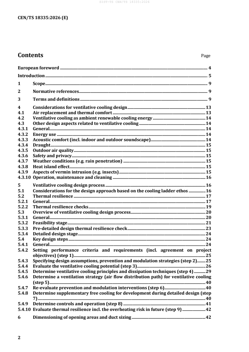
Contents Page
European foreword . 4
Introduction . 5
1 Scope . 9
2 Normative references . 9
3 Terms and definitions . 9
4 Considerations for ventilative cooling design . 13
4.1 Air replacement and thermal comfort . 13
4.2 Ventilative cooling as ambient renewable cooling energy . 14
4.3 Other design aspects related to ventilative cooling . 14
4.3.1 General. 14
4.3.2 Energy use . 14
4.3.3 Acoustic comfort (incl. indoor and outdoor soundscape). 14
4.3.4 Draught . 15
4.3.5 Outdoor air quality . 15
4.3.6 Safety and privacy . 15
4.3.7 Weather conditions (e.g. rain penetration) . 15
4.3.8 Heat island effect . 15
4.3.9 Aspects of vermin intrusion (e.g. insects) . 15
4.3.10 Operation, maintenance and cleaning . 16
5 Ventilative cooling design process . 16
5.1 Considerations for the design approach based on the cooling ladder ethos . 16
5.2 Thermal resilience . 17
5.2.1 General. 17
5.2.2 Thermal resilience checks . 19
5.3 Overview of ventilative cooling design process . 20
5.3.1 General. 20
5.3.2 Feasibility stage . 21
5.3.3 Pre-detailed design thermal resilience check . 23
5.3.4 Detailed design stage . 24
5.4 Key design steps . 24
5.4.1 General. 24
5.4.2 Setting performance criteria and requirements (incl. agreement on project
objectives) (step 1) . 25
5.4.3 Specifying design assumptions, prevention and modulation strategies (step 2). 25
5.4.4 Evaluate the ventilative cooling potential (step 3) . 26
5.4.5 Determine ventilative cooling principles and dissipation techniques (step 4) . 29
5.4.6 Determine a ventilation strategy (air flow distribution path) for ventilative cooling
(step 5) . 40
5.4.7 Re-evaluate prevention and modulation interventions (step 6). 40
5.4.8 Determine supplementary free cooling for development during detailed design (step
7) . 40
5.4.9 Determine controls and operation (step 8) . 41
5.4.10 Evaluate thermal resilience incl. the overheating risk in future (step 9) . 42
6 Dimensioning of opening areas and duct sizing . 42
6.1 General . 42
6.2 Sizing of ventilative cooling systems . 43
Annex A (informative) Further considerations for ventilative cooling design . 44
Annex B (informative) Climatic boundary conditions, building constraints and complexity
................................................................................................................................................................... 48
Annex C (informative) Natural ventilative cooling system design . 54
Annex D (informative) Mechanical ventilative cooling system design . 62
Annex E (informative) Hybrid ventilative cooling system design . 67
Annex F (informative) Controls and operation . 71
Annex G (informative) Supplementary free cooling systems – description and interaction
with ventilative cooling . 74
Annex H (informative) Ventilative cooling potential method (VCPM) . 80
Annex I (informative) Example of safety and privacy (Belgium) . 95
Annex J (informative) Comparison of ventilative cooling potential method with dynamic
simulations of case study (Irish classrooms) . 97
Annex K (informative) Ambient renewable energy for cooling using ventilative cooling . 101
Annex L (informative) Thermal resilience and thermal comfort indices (KPIs) . 103
Annex M (informative) Calculations for sizing of opening areas and ducts incl. examples 105
Bibliography . 110
European foreword
This document (CEN/TS 18335:2026) has been prepared by Technical Committee CEN/TC 156
“Ventilation for buildings”, the secretariat of which is held by BSI.
Attention is drawn to the possibility that some of the elements of this document may be the subject of
patent rights. CENELEC shall not be held responsible for identifying any or all such patent rights.
Any feedback and questions on this document should be directed to the users’ national committee. A
complete listing of these bodies can be found on the CENELEC website.
Introduction
0.1 Purpose and background
Rising global temperatures and urbanization increase the risk of overheating in buildings, affecting
occupants' health and comfort throughout summer and increasingly in spring and autumn, periods
during which an ageing population can be more vulnerable to this phenomenon. As people spend around
90 % of their time indoors, buildings ought to effectively protect occupants from heatwaves and rising
temperatures.
Higher ambient temperatures significantly boost energy demands for active cooling, posing substantial
environmental challenges. By 2050, global energy use for space cooling could triple compared to 2016
levels, potentially doubling related CO emissions, with the residential sector accounting for about 70 %
of this increase [1].
Implementing passive cooling strategies – such as better insulation, solar shading, and ventilative cooling
– is critical to reducing overheating, decreasing energy use, and safeguarding occupant health, especially
for vulnerable populations.
The increasing energy demand (for cooling) in buildings is putting a big strain on the electricity grid,
which in many countries could cause grid congestion and intermittent power outages. When designing
buildings for future resilience there should be a cooling strategy in place on how to reduce the potential
for internal overheating with no or a minimal use of active cooling. The cooling ladder ethos, as part of
this document [2] offers a design strategy for resilient buildings by firstly mitigating the solar and internal
gains and later if overheating has taken place, to first provide cooling with use of passive means (e.g.
ventilative cooling) prior to moving to active means (e.g. active cooling). To diminish the impact of
(cooling) energy use in buildings on the climate change, appropriate guidelines of cooling design from
free cooling solutions such as ventilative cooling, to supplementary free cooling and interventions are
included in this document.
Overheating relates to a range of conditions under which people experience thermal discomfort and
cannot be adequately defined by a single measurable value of temperature. The rate of increase in
temperature, the temperature reached, the time for which the temperature stays high and individual
tolerance are all important factors, as well as humidity factors.
The necessary decarbonisation of the European Union building stock requires renovation at a large scale:
almost 75 % of that building stock is inefficient according to current building standards, and 85 to 95 %
of the buildings that exist today will still be standing in 2050 [3].
0.2 Addressing overheating risks through cooling strategies in buildings
Factors such as the same building envelope insulation, increased solar gains, and highly insulated
windows can contribute to overheating, leading to higher energy usage due to increased active cooling.
This is not ideal for the world’s total energy usage, at the same time, the free cooling techniques (e.g.
ventilative cooling, dynamic solar shading) are generally not yet taken properly into account; since
guidelines, standards and legislation do not really consider the relevant potential of free cooling solutions
and supplementary modulations sufficiently yet. Though some mitigation policies on limitation of
overheating (e.g. heat protection) have been implemented nationally such as green roofs, criteria for
green spaces, the need for solar shading systems etc.
However, buildings designed without consideration for potential overheating mitigation are foreseen in
the future to be at risk of discomfort in cooling season and rising costs (and relative direct or indirect CO
emissions) for vast use of active cooling, causing higher energy usage in buildings, which in the long term
is not sustainable for the planet.
In many new or renewed buildings, technical solutions for the building envelope in combination with the
HVAC systems have in recent times become more complex. Moreover, there is a growing worry about
potential overheating in Zero Emission Buildings (ZEB) design, paying a growing attention to the
limitation of the potential extended use of air conditioning as an active cooling solution to provide indoor
space cooling, encouraging at the same time a systematic approach to largely use free cooling techniques
(e.g. ventilative cooling, dynamic solar shading, solar reflective index) as a first design action to mitigate
overheating. It is essential to use the full potential of passive technologies to mitigate or reverse rising
electricity use from space cooling, the use of ventilative cooling is considered a very important solution.
There are already excellent approaches in this direction, for example, the cooling hierarchy defined into
London’s response to climate change, which seeks to reduce any potential overheating and to reduce as
much as possible the need to cool a building through active cooling measures [2]. The cooling ladder
described in this document implements this philosophy.
Ventilative cooling should find proper consideration in existing buildings undergoing major renovation
or deep renovation (as defined in article 1(20) of EPBD) which in Europe will be a relevant part of work
to be done to reach carbon neutrality by 2050, taking into consideration constraints and sometimes space
limitations in existing buildings to be renewed. Regarding new buildings, ventilative cooling should also
find proper consideration as these buildings can permit a much easier integration of several ventilative
cooling techniques.
In situations where the additional ventilation air flow rate is increased above the standard ventilation air
flow rate requirement (standard ventilation) for cooling purposes, the cooling contribution resulting
from this additional air flow may be taken into account in calculations relating to renewable cooling as
indicated by [4]. For more information see 4.2.
0.3 Means to overcome overheating
Ventilative cooling is one of many cooling solutions to mitigate overheating, which can, either alone or in
combination with supplementary or active cooling systems, create acceptable thermal comfort or
decrease cooling loads (can be both peak and annual) in buildings. Ventilative cooling is free cooling that
relies on the actual temperature of natural elements such as outdoor air, aiming at mitigating overheating
where air transfer may be by natural, mechanical or hybrid means.
Ventilative cooling enables new and refurbished buildings to adapt to climate change in terms of
resilience, such as recoverability and this is integrated into the 9 key design steps for ventilative cooling
system design.
Reducing the cooling load can reduce the reliance on active cooling systems and mitigate the risk of
overheating. Under the right outdoor conditions, indoor air quality can be improved when air flow rates
are increased compared to standard ventilation air flow rates. Often a combination of ventilative cooling,
external solar shading and thermal mass is the optimal solution to achieving acceptable thermal comfort
during prolonged hot spells and to mitigate the effect of climate change.
Reasons for choosing ventilative cooling:
— is a part of a resilient cooling strategy to ensure that buildings are enhanced for climate change in
regard to:
— energy shortage and grid congestion
— availability
— achieving acceptable thermal comfort during power outages.
— can reduce energy use during times when there is a cooling demand, possibly eliminating or reducing
the need for active cooling systems under suitable outside conditions.
— can contribute to building flexibility by shedding or shifting thermal peaks
— is a type of renewable energy, as outdoor air is a renewable source for cooling at air flows above the
standard ventilation air flow rate (see 4.2 and Annex K). This includes natural, mechanical as well as
hybrid ventilative cooling, as the outdoor air (unprocessed) is the source of ventilative cooling.
Generally, resilient cooling is used to denote low energy and low carbon cooling solutions that strengthen
the ability of individuals, and the community as a whole to withstand, and also prevent, the thermal and
other impacts of changes in global and local climates, particularly with respect to increasing ambient
temperatures and the increasing frequency and severity of heat waves [5].
Finally, it is evident that resilient cooling solutions, such as free cooling provided as ventilative cooling
and supplementary free cooling and additional design interventions (thermal mass, solar shading), offer
potential technical solutions to respond to the expected increase space cooling demand.
0.4 Connection to European Standards
This document sets the design framework for how to design ventilative cooling systems to cope with the
set criteria, estimating how much ventilative cooling can be used in residential and non-residential
buildings before having to assist with supplementary free cooling or active cooling. Further it is a “system
design” document much like EN 15665 [6] and EN 16798-3 [7] referencing existing EPB standards, e.g.
thermal comfort criteria in EN 16798-1 or national regulations, see Figure 1.
Figure 1 — Overview of design and KPI standards in Europe (existing and under development)
This document refers to the new edition of EN 16798-1 [8] for thermal comfort criteria to be reached by
the design of buildings with ventilative cooling strategies. This document explains how to design
ventilative cooling systems and could be used as a reference in relevant EPB standards.
NOTE The new editions of EN 15665 and EN 16798-1 will be adopted depending on document progress.
Table 1 shows the dependencies between this document and other related European EPB standards for
residential and non-residential buildings.
Table 1 — Dependencies between this document and EPB standards
IEQ criteria Building Building Calculation of Ventilation Ventilation
energy needs automation air flow rates energy energy
“Ventilati EN 16798-1:20 EN EN EN 16798-7:20 EN 16798-5-1:2 EN 16798-5-2:2
ve cooling 19 [9] ISO 52016-1:2 ISO 52120-1:2 17 [12] 017 (only for 017 (only for
systems – 017 [10] 022 (only for Mechanical Hybrid and
Design” Mechanical ventilation and Mechanical
(CEN/TS) ventilation and active cooling) ventilation) [14]
active cooling) [13]
[11]
1 Scope
This document gives guidance to the design of ventilative cooling systems while referring to relevant
standards to ensure coherence and avoiding overlapping. In this document different design approaches
for use of natural, mechanical or hybrid ventilative cooling can be found, starting at the feasibility phase
before going into the design phase. In addition, this document gives guidance on where to find additional
information on the design, calculation and maintenance of such systems.
This document is applicable to buildings specified according to the thermal indoor environmental aspects
used for human occupancy where production processes don’t have a major impact on the indoor
environmental quality. This document is applicable to residential and non-residential buildings.
This document applies to all types of buildings: new and retrofit, residential and non-residential.
This document is applicable to:
— mechanical ventilative cooling
— natural ventilative cooling
— hybrid ventilative cooling
— airing as a supplement to ventilative cooling specifically relevant during e.g. power failures
— supplementary free cooling as a supplement to ventilative cooling
The design of supplementary free cooling systems and active cooling systems are not part of the
normative part of the document. However, the interface between ventilative cooling systems and
supplementary free cooling systems as well as the interface between ventilative cooling and active
cooling systems are mentioned informatively.
Design of ventilative cooling systems commonly considers other aspects like energy use, acoustic,
draught, solar gain control, outdoor air quality, user acceptance, burglary and cleaning and maintenance,
though these are not covered in detail in this document.
This document only covers temperature control.
This document does not apply to:
— moisture control
— waterborne
— heat losses.
2 Normative references
The following documents are referred to in the text in such a way that some or all their content constitutes
requirements of this document. For dated references, only the edition cited applies. For undated
references, the latest edition of the referenced document (including any amendments) applies.
EN 12792, Ventilation for buildings - Symbols, terminology and graphical symbols
3 Terms and definitions
For the purposes of this document, the terms and definitions given in EN 12792 and the following apply.
ISO and IEC maintain terminology databases for use in standardization at the following addresses:
— ISO Online browsing platform: available at https://www.iso.org/obp
— IEC Electropedia: available at https://www.electropedia.org/
3.1
air replacement
process of replacing the air within an enclosure with air coming directly from outdoors or passing
through a transfer zone or both
Note 1 to entry: Air replacement can be done through ventilation, airing and air leakage airing.
3.2
standard ventilation
ventilation to achieve acceptable indoor air quality under normal occupancy
Note 1 to entry: Acceptable indoor air quality can be linked with occupants or building needs.
3.3
intensive ventilation
ventilation at significantly higher air flow rate than that of standard ventilation for a specific purpose
limited in time
3.4
natural ventilation
ventilation whose operating principle is based solely on the effect of wind and the stack effect
Note 1 to entry: Open windows, e.g. roof windows, rooflights and roof hatches can be used for natural ventilation
if they are purpose-provided.
3.5
mechanical ventilation
ventilation whose operating principle is based solely on the operation of fans
3.6
hybrid ventilation
ventilation whose operating principle is based on the combination of natural ventilation and mechanical
ventilation
Note 1 to entry: Natural ventilation and mechanical ventilation can take place simultaneously or alternately.
3.7
airing
air replacement by means that are not purpose-provided
Note 1 to entry: Usually done through manual opening of doors or windows, louvres or both.
3.8
stack effect
pressure difference caused by the difference in density between indoor air and outdoor air due to their
temperature difference
3.9
cross ventilation
natural ventilation which relies on vents located on different sides of a building or room
Note 1 to entry: Cross ventilation mainly relies on the effect of the wind.
Note 2 to entry: The concept of side includes façades and roofs.
3.10
cooling
removal of heat
Note 1 to entry: There are two types of heat: latent heat and sensible heat.
3.11
free cooling
natural cooling
cooling that relies on the actual temperature of natural elements or on the evaporation of water
Note 1 to entry: Free cooling includes ventilative cooling, supplementary free cooling, etc.
Note 2 to entry: Free cooling does not use any kind of mechanical compressors (like chillers, air-conditioners, or
heat pumps).
Note 3 to entry: Examples of natural elements are outdoor air, surface water, groundwater and earth.
3.12
ventilative cooling
free cooling, relying on outdoor air only, by means of ventilation or airing
Note 1 to entry: Ventilation can be natural, mechanical or hybrid.
Note 2 to entry: While ventilative cooling is not limited to ventilation, the adjective “ventilative” has been retained
because of its widespread use in the field.
3.13
natural ventilative cooling
free cooling by natural ventilation
ventilative cooling whose operation is based solely on the effect of wind and the stack effect
3.14
mechanical ventilative cooling
free cooling by mechanical ventilation
ventilative cooling whose operation is based solely on the operation of fans
3.15
hybrid ventilative cooling
free cooling by hybrid ventilation
ventilative cooling whose operation is based on the combination of natural and mechanical ventilative
cooling
3.16
vent
opening in the building envelope that is intended for the passage of air
EXAMPLE externally mounted air transfer device, intake air terminal device, wall and window louvres, façade
windows, rooflights, roof outlet or roof windows
3.17
descriptive requirement
requirement in the form of a specified technical solution
EXAMPLE minimum opening area
3.18
performance-based approach
performance-based method
way of considering something guided by performance-based requirement(s)
Note 1 to entry: The assessment of the criteria is done through calculations or simulations.
3.19
intake air
air that is taken in from outside a building by ventilation or by airing
3.20
supply air
air that is provided inside a building by ventilation or by airing
3.21
extract air
air that is removed from inside a building by ventilation or by airing
3.22
exhaust air
air that is discharged to outside a building by ventilation or by airing
3.23
hybrid cooling
combination of free cooling and active cooling
Note 1 to entry: The control can be alternation or simultaneous.
3.24
supplementary free cooling
cooling that relies not only on the actual temperature difference between outdoor air and indoor air but
also uses additional natural potentials
EXAMPLE evaporative cooling or ground cooling
3.25
thermal resilience
ability to prepare and plan for, resist, adapt to, or recover from an adverse, potentially disruptive, event
Note 1 to entry: In the field of buildings, resilience concerns among others their thermal performance or their
protection against precipitations, particularly during extreme weather events arising from climate change.
3.26
night cooling
ventilative cooling during nighttime
3.27
active cooling
mechanical cooling
cooling by means of a device that uses energy to lower the temperature of a fluid or solid, except where
the energy is used solely to move the fluid
Note 1 to entry: It includes for example mechanical cooling and thermoelectric cooling.
EXAMPLE vapour-compression refrigeration, fan coil units, chilled ceilings, beams cooled surfaces
4 Considerations for ventilative cooling design
4.1 Air replacement and thermal comfort
Ventilation is needed to provide oxygen for metabolism and to dilute pollutants (odour, CO as a proxy
for other pollutants etc.). Ventilation systems can also be designed for cooling purposes with elevated air
flow rates above the standard ventilation air flow rate, where ventilative cooling is one of the solutions,
to achieve an acceptable thermal comfort.
Air flow rates can also be significantly increased for a given period of time to address peak situations
(intensive ventilation) with respect to ventilation but can also permanently be increased with the
purpose of achieving acceptable thermal comfort using ventilative cooling. This can be done by whatever
the operating principles (mechanical ventilative cooling, natural ventilative cooling or hybrid ventilative
cooling).
An essential aspect of the design process is to identify how much air replacement is to be provided to a
space, to at least maintain the indoor thermal comfort where too little can result in poor thermal comfort,
while too much could result in an increased energy use and cause draught. Using descriptive
requirements, air replacement rates can also be equivalently converted to design opening areas.
For residential use, increased night cooling could ideally occur through roofs, facades or away from street
level, in e.g. stairways or open areas if the vents are placed ideally. Further the possibility of increased
day and night cooling can generally be assumed, however care should be taken to ensure there are no
risks associated with burglary, noise, pollution etc. Effective night cooling, but also day cooling depends
on aspects such as adequate thermal mass, placement of openings, occupancy, comfort zones, level of
automated functioning etc. With a more optimized system and building design, higher air flow rates
should be allowed.
For non-residential use, increased night cooling could occur in e.g. corridors if the vents are placed ideally
and secured through actuators due to lack of occupancy during night in the buildings. Further indoor
resistances are important to take into account.
NOTE For more information on night cooling see Annex C.
Under appropriate conditions, airing is a very effective means to cool down buildings during e.g. power
failures or specific events like night cooling.
Ventilative cooling can be either manual or automatic operation of vents, like openable windows,
rooflights and roof hatches for natural ventilative cooling. Wall switches can also control e.g. roof
windows, louvres, rooflights and roof hatches.
For specific requirements on classifications of thermal comfort see EN 16798-1 [9]. For buildings without
active cooling the adaptive comfort method should be considered, applying for occupants with sedentary
activities without strict clothing policies where thermal conditions are regulated primarily by the
occupants through opening and closing of elements in the building envelope (e.g. windows, ventilation
flaps, louvres, rooflights).
4.2 Ventilative cooling as ambient renewable cooling energy
Ventilative cooling can be achieved through free natural, mechanical, or hybrid cooling solutions, now
considered part of the renewable energy cooling calculations, as according to the ‘whereas’ of
Commission Delegated Regulation (EU) 2022/759, amending Annex VII to Directive (EU) 2018/2001,
this additional air flow for cooling, as ambient air energy is recognized as an ambient renewable source
under Directive (EU) 2018/2001 (Renewable Energy Directive (RED II)) as regards a methodology for
calculating the amount of renewable energy used for cooling and district cooling, as set out in Article 7(3)
of Directive (EU) 2018/2001.
Free cooling, through natural ventilative cooling, mechanical ventilative cooling as well as hybrid
ventilative cooling, plays a significant role in enhancing the energy efficiency of buildings. By calculating
the additional air flow for cooling and integrating this into ambient renewable cooling contributions,
buildings can achieve significant energy savings and environmental benefits. The methodology involves
understanding the baseline ventilation requirements, calculating the extra air flow, quantifying the
cooling supply, and considering fan energy consumption (in case of mechanical ventilation).
To assume that natural and mechanical systems are actuated and that they are deliberately operated,
based on a schedule or sensors. This aspect fulfils the intentionality requirement in the operation of the
system which is a key aspect of the (RED II) definition to achieve ambient renewable cooling status.
For further information on ventilative cooling as renewable energy for cooling see Annex K.
4.3 Other design aspects related to ventilative cooling
4.3.1 General
The design aspects related to ventilative cooling are normally not limited to thermal comfort
requirements only, but also include other design aspects like energy use, acoustics, or draughts. Such
design aspects should be considered during the design phase.
4.3.2 Energy use
Energy use for e.g. actuators or fans for vent operations should be considered when designing the
ventilative cooling system. There is a balance to be achieved between thermal comfort and energy
efficiency in the design of a ventilative cooling system.
NOTE EN 16798-5-1 and CEN/TR 16798-6 are about calculation of energy requirements for mechanical
ventilation and air conditioning systems.
4.3.3 Acoustic comfort (incl. indoor and outdoor soundscape)
Acoustic comfort associated with ventilative cooling should be considered when designing the ventilative
cooling system, with the following possible aspects:
— indoor acoustic environment as perceived or experienced or understood by a person or people, in the
context defined by the building (indoor soundscape)
— outdoor acoustic environment as perceived or experienced or understood by a person or people, in
the context defined by the building (outdoor soundscape)
The noise caused by ventilative cooling systems can affect the acoustic comfort of occupants and hence
influence their use of the ventilative cooling system. These side effects depend on the occupancy
(residential or non-residential) and the occupancy patterns/activities.
NOTE Basic information on possible acoustic comfort criteria can be found in EN 16798-1 [9] as well as in
national legislation.
4.3.4 Draught
Draught associated with ventilative cooling should be considered when designing the ventilative cooling
system.
NOTE EN ISO 7730 [15] and EN 16798-1 [9] provides basic information on possible criteria on draught.
4.3.5 Outdoor air quality
The outdoor air quality should be considered when designing the ventilative cooling system.
Technical solutions to handle outdoor pollutants include, for example, proper placement of intake vents,
demand controlled ventilative cooling based on outdoor air quality or air cleaning and filtration.
NOTE For mechanical ventilative cooling systems, information for filtration is available in EN 16798-3.
4.3.6 Safety and privacy
Safety and privacy associated with ventilative cooling should be considered when designing the
ventilative cooling system. To be able to address the full potential of a ventilative cooling system, it should
be possible to operate openings for ventilative cooling regardless of a burglary risk. The risk is related to
the accessibility in relation to burglary of the openings.
NOTE 1 EN 1627 provides information on possible criteria and classifications for burglary resistance.
NOTE 2 In terms of safety and privacy there is a difference in expectations between natural and mechanical
ventilative cooling systems.
NOTE 3 See Annex I for more information on accessibility in relation to burglary.
4.3.7 Weather conditions (e.g. rain penetration)
The aspect of weather conditions (e.g. rain penetration and high wind speeds) associated to ventilative
cooling should be considered when designing the ventilative cooling system.
To be able to address the full potential of a ventilative cooling system, openings for ventilative cooling
systems should be designed to minimize the risk of ingress of rain and elevated wind speeds.
NOTE Taking elevated wind speeds into account is also an important factor during the design process.
4.3.8 Heat island effect
The heat island effect, particularly in urban areas, should be considered when designing ventilative
cooling systems. Air flow rates should thereby be increased.
4.3.9 Aspects of vermin intrusion (e.g. insects)
The aspect of insects and vermin intrusion associated to ventilative cooling should be considered, if
relevant for the use of the ventilated spaces, when designing the ventilative cooling system.
To fully harness the potential of a ventilative cooling system, the design of its openings should, if relevant,
consider the specific use of the ventilated spaces, minimizing the entry of insects and vermin into the
building.
NOTE Insect screens can affect the air flow through openings intended for ventilative cooling purposes. The
discharge coefficient and pressure loss depend on the mesh configuration.
4.3.10 Operation, maintenance and cleaning
Cleaning and maintenance of the ventilative cooling system are important to maintain an acceptable
performance over time.
During the design of the ventilative cooling system, the following aspects should be considered:
— Accessibility to the components to be replaced (e.g. the filters, actuators, controls)
— Accessibility to the components to be cleaned (e.g. ducts, air supply, fans, air transfer devices or air
terminal devices)
— The use of filters can also help to protect the mechanical ventilative cooling system against fouling.
NOTE 1 Information about requirements for ductwork components to facilitate maintenance of ductwork
systems is available in EN 12097.
NOTE 2 Information about cleanliness of mechanical ventilation systems is available in EN 15780 [16].
5 Ventilative cooling design process
5.1 Considerations for the design approach based on the cooling ladder ethos
The cooling ladder in Figure 2 includes four sequential actions: prevention/protection, modulation,
dissipation of heat, supplementary free cooling and integration of active cooling. Designing with the
cooling ladder in mind prioritises free cooling and low energy solutions before resorting to active cooling
systems.
It emphasizes building design and materials to minimize heat gain and enhance free cooling potential.
The cooling ladder design ethos corresponds and is in line with the cooling hierarchy set in the Mayor of
London’s Energy Assessment Guidance on overheating and cooling [2].
The design of a ventilative cooling system as a dissipation technique in action 3 is an iterative process,
whereby the prevention, modulation and dissipation of heat should be re-considered iteratively if the
desired thermal comfort is not reached, until all possible additional design interventions have been
evaluated. Additional design interventions are the evaluation and utilisation of interventions at the level
of the neighbourhood, building or room, provided that the design concept has been optimised for
ventilative cooling. More information on the different additional design interventions can be found in
Clause A.1
For dissipation techniques, the ventilative cooling potential shall be evaluated, estimating if ventilative
cooling strategies for overheating mitigation and reducing cooling loads in buildings can be used. This
methodology helps determine to what extent ventilative cooling can be utilized before supplementary
free cooling or active cooling systems are needed. The ventilative cooling potential method assesses the
ventilative cooling potential in a reference thermal and ventilation zone representing the building and
users’ needs (hygienic ventilation rates, comfort category, maximum relative humidity) relying on basic
information on prevention/protection and modulation measures such as the thermal transmittance of
the building envelope, the thermal mass of the building and the presence of solar shading devices. The
Ventilative cooling potential method provides insights in when ventilative cooling is needed, required air
flow rates, hourly, monthly and annual sensible energy needs for cooling with and without the application
of ventilative cooling, and consequently the ventilative cooling capacity
NOTE This information supports the decision-making process in designing ventilative cooling systems and
integrating them into the cooling ladder to achieve optimal thermal comfort and energy efficiency.
Thermal comfort should be evaluated on an hourly basis to ensure that variations in indoor
environmental conditions over time are adequately captured.
Figure 2 — Cooling ladder design ethos
Detailed information on this approach is given in Clause A.1.
5.2 Thermal resilience
5.2.1 General
...