

oSIST prEN 50173-10:2026
(Main)Information technology - Generic cabling systems - Part 10: Single pair cabling
- Abstract
This document specifies 1-pair cabling and can be used in conjunction with all the space-specific standards of the EN 50173 series but especially EN 50173-3 and EN 50173-6.
NOTE 1-pair cabling for EN 50173-2, EN 50173-4 and EN 50173-5 is for further study.
It delivers 1-pair cabling specifications to extend generic cabling systems according to the EN 50173 series.
This document specifies the:
— structure and minimum configuration for extension of generic cabling by 1-pair cabling;
— interfaces at the service outlet (SO/TO);
— performance requirements for cabling links and channels;
— implementation requirements and options;
— performance requirements for cabling components;
— conformance requirements and verification procedures.
This document takes into account the requirements specified in application standards listed in Annex C.
- Status
- Not Published
- Public Enquiry End Date
- 30-Dec-2026
- Technical Committee
- ELI - Electrical and communication installations
- Current Stage
- 4020 - Public enquire (PE) (Adopted Project)
- Start Date
- 03-Nov-2026
- Due Date
- 23-Mar-2027


Relations
- Effective Date
- 23-Dec-2025
Get Certified
Connect with accredited certification bodies for this standard

BSI Group
BSI (British Standards Institution) is the business standards company that helps organizations make excellence a habit.

NYCE
Mexican standards and certification body.

ANCE
Mexican certification and testing association.
Sponsored listings
Frequently Asked Questions
oSIST prEN 50173-10:2026 is a draft published by the Slovenian Institute for Standardization (SIST). Its full title is "Information technology - Generic cabling systems - Part 10: Single pair cabling". This standard covers: This document specifies 1-pair cabling and can be used in conjunction with all the space-specific standards of the EN 50173 series but especially EN 50173-3 and EN 50173-6. NOTE 1-pair cabling for EN 50173-2, EN 50173-4 and EN 50173-5 is for further study. It delivers 1-pair cabling specifications to extend generic cabling systems according to the EN 50173 series. This document specifies the: — structure and minimum configuration for extension of generic cabling by 1-pair cabling; — interfaces at the service outlet (SO/TO); — performance requirements for cabling links and channels; — implementation requirements and options; — performance requirements for cabling components; — conformance requirements and verification procedures. This document takes into account the requirements specified in application standards listed in Annex C.
This document specifies 1-pair cabling and can be used in conjunction with all the space-specific standards of the EN 50173 series but especially EN 50173-3 and EN 50173-6. NOTE 1-pair cabling for EN 50173-2, EN 50173-4 and EN 50173-5 is for further study. It delivers 1-pair cabling specifications to extend generic cabling systems according to the EN 50173 series. This document specifies the: — structure and minimum configuration for extension of generic cabling by 1-pair cabling; — interfaces at the service outlet (SO/TO); — performance requirements for cabling links and channels; — implementation requirements and options; — performance requirements for cabling components; — conformance requirements and verification procedures. This document takes into account the requirements specified in application standards listed in Annex C.
oSIST prEN 50173-10:2026 is classified under the following ICS (International Classification for Standards) categories: 33.040.50 - Lines, connections and circuits; 35.110 - Networking. The ICS classification helps identify the subject area and facilitates finding related standards.
oSIST prEN 50173-10:2026 has the following relationships with other standards: It is inter standard links to SIST EN 50173-10:2025. Understanding these relationships helps ensure you are using the most current and applicable version of the standard.
oSIST prEN 50173-10:2026 is available in PDF format for immediate download after purchase. The document can be added to your cart and obtained through the secure checkout process. Digital delivery ensures instant access to the complete standard document.
Standards Content (Sample)
SLOVENSKI STANDARD
01-december-2026
Informacijska tehnologija - Generični kabelski sistemi - 10. del: Enoparično
okablenje
Information technology - Generic cabling systems - Part 10: Single pair cabling
Informationstechnik - Anwendungsneutrale Kommunikationskabelanlagen - Teil 10:
Einpaarige Verkabelung
Technologies de l'information - Systèmes de câblage générique - Partie 10: Câblage
mono-paire
Ta slovenski standard je istoveten z: prEN 50173-10:2026
ICS:
33.040.50 Vodi, zveze in tokokrogi Lines, connections and
circuits
35.110 Omreževanje Networking
2003-01.Slovenski inštitut za standardizacijo. Razmnoževanje celote ali delov tega standarda ni dovoljeno.
EUROPEAN STANDARD DRAFT
prEN 50173-10
NORME EUROPÉENNE
EUROPÄISCHE NORM
October 2026
ICS 35.110 Will supersede EN 50173-10:2025
English Version
Information technology - Generic cabling systems - Part 10:
Single pair cabling
Technologies de l'information - Systèmes de câblage Informationstechnik - Anwendungsneutrale
générique - Partie 10: Câblage mono-paire Kommunikationskabelanlagen - Teil 10: Einpaarige
Verkabelung
This draft European Standard is submitted to CENELEC members for enquiry.
Deadline for CENELEC: 2027-01-08.
It has been drawn up by CLC/TC 215.
If this draft becomes a European Standard, CENELEC members are bound to comply with the CEN/CENELEC Internal Regulations which
stipulate the conditions for giving this European Standard the status of a national standard without any alteration.
This draft European Standard was established by CENELEC in three official versions (English, French, German).
A version in any other language made by translation under the responsibility of a CENELEC member into its own language and notified to
the CEN-CENELEC Management Centre has the same status as the official versions.
CENELEC members are the national electrotechnical committees of Austria, Belgium, Bulgaria, Croatia, Cyprus, the Czech Republic,
Denmark, Estonia, Finland, France, Germany, Greece, Hungary, Iceland, Ireland, Italy, Latvia, Lithuania, Luxembourg, Malta, the
Netherlands, Norway, Poland, Portugal, Republic of North Macedonia, Romania, Serbia, Slovakia, Slovenia, Spain, Sweden, Switzerland,
Türkiye and the United Kingdom.
Recipients of this draft are invited to submit, with their comments, notification of any relevant patent rights of which they are aware and to
provide supporting documentation.
Warning : This document is not a European Standard. It is distributed for review and comments. It is subject to change without notice and
shall not be referred to as a European Standard.
European Committee for Electrotechnical Standardization
Comité Européen de Normalisation Electrotechnique
Europäisches Komitee für Elektrotechnische Normung
CEN-CENELEC Management Centre: Rue de la Science 23, B-1040 Brussels
© 2026 CENELEC All rights of exploitation in any form and by any means reserved worldwide for CENELEC Members.
Project: 83175 Ref. No. prEN 50173-10:2026 E
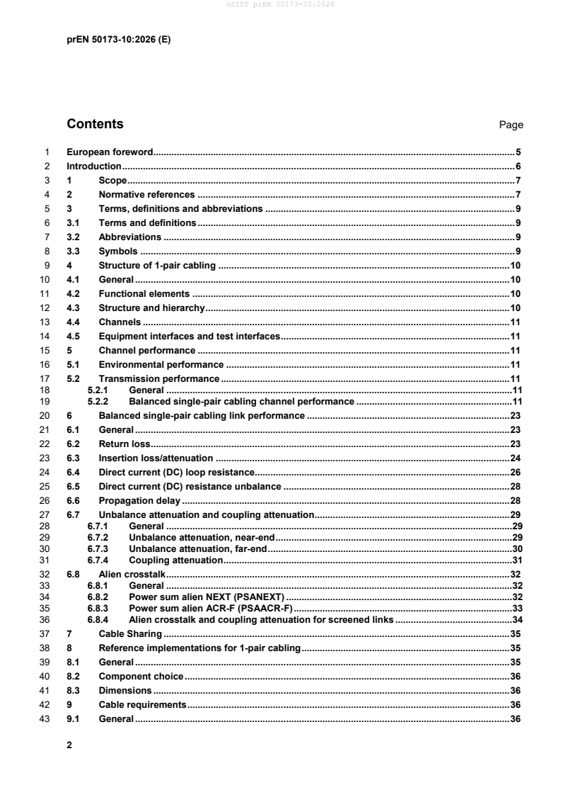
Contents Page
1 European foreword . 5
2 Introduction . 6
3 1 Scope . 7
4 2 Normative references . 7
5 3 Terms, definitions and abbreviations . 9
6 3.1 Terms and definitions . 9
7 3.2 Abbreviations . 9
8 3.3 Symbols . 9
9 4 Structure of 1-pair cabling . 10
10 4.1 General . 10
11 4.2 Functional elements . 10
12 4.3 Structure and hierarchy . 10
13 4.4 Channels . 11
14 4.5 Equipment interfaces and test interfaces . 11
15 5 Channel performance . 11
16 5.1 Environmental performance . 11
17 5.2 Transmission performance . 11
18 5.2.1 General . 11
19 5.2.2 Balanced single-pair cabling channel performance . 11
20 6 Balanced single-pair cabling link performance . 23
21 6.1 General . 23
22 6.2 Return loss . 23
23 6.3 Insertion loss/attenuation . 24
24 6.4 Direct current (DC) loop resistance. 26
25 6.5 Direct current (DC) resistance unbalance . 28
26 6.6 Propagation delay . 28
27 6.7 Unbalance attenuation and coupling attenuation . 29
28 6.7.1 General . 29
29 6.7.2 Unbalance attenuation, near-end . 29
30 6.7.3 Unbalance attenuation, far-end . 30
31 6.7.4 Coupling attenuation . 31
32 6.8 Alien crosstalk . 32
33 6.8.1 General . 32
34 6.8.2 Power sum alien NEXT (PSANEXT) . 32
35 6.8.3 Power sum alien ACR-F (PSAACR-F) . 33
36 6.8.4 Alien crosstalk and coupling attenuation for screened links . 34
37 7 Cable Sharing . 35
38 8 Reference implementations for 1-pair cabling . 35
39 8.1 General . 35
40 8.2 Component choice . 36
41 8.3 Dimensions . 36
42 9 Cable requirements . 36
43 9.1 General . 36
44 9.2 Operating environment . 36
45 9.3 Balanced cables - Basic performance requirements . 36
46 10 Connecting hardware requirements. 37
47 10.1 General requirements . 37
48 10.1.1 Overview . 37
49 10.1.2 Location . 38
50 10.1.3 Design . 38
51 10.1.4 Operating environment . 38
52 10.2 Connecting hardware . 38
53 10.2.1 General . 38
54 10.2.2 Performance marking . 40
55 10.2.3 Electrical, mechanical and environmental performance . 40
56 10.2.4 Connecting hardware in accordance with EN IEC 63171-1 . 40
57 10.2.5 Connecting hardware in accordance with IEC 63171-6 . 41
58 10.3 Performance marking . 41
59 11 Requirements for cords and jumpers . 41
60 11.1 General . 41
61 11.2 Identification . 41
62 11.3 Operating requirement . 42
63 11.4 Return Loss . 42
64 Annex A (informative) Relationship of EN 50173-10 to other documents and practical
65 considerations . 43
66 Annex B (informative) Cable sharing . 45
67 B.1 General . 45
68 B.2 Simultaneous operation of multiple single pair applications within a system that
69 includes 4-pair cabling components according to EN 50173-1 . 45
70 B.2.1 General . 45
71 B.2.2 Creation of single pair cabling channels . 46
72 B.3 Evaluation of the parameters that need to be fulfilled by the shared 4-pair SCP link . 46
73 B.3.1 General . 46
74 B.3.2 T1-60 and T1-60A. 46
75 B.3.3 T1-600 . 48
76 B.4 Guidance . 48
77 B.4.1 General . 48
78 B.4.2 Frequency range . 49
79 B.4.3 Return loss . 49
80 B.4.4 Insertion loss . 49
81 B.4.5 Direct current (DC) Loop resistance . 49
82 B.4.6 Direct current (DC) resistance unbalance . 50
83 B.4.7 Current carrying capacity . 50
84 B.4.8 Dielectric withstand voltage . 50
85 B.4.9 Propagation delay . 50
86 B.4.10 Unbalance attenuation (TCL and ELTCTL) . 50
87 B.4.11 Coupling attenuation . 50
88 B.4.12 Alien crosstalk (PSANEXT and PSAACR-F) . 50
89 B.4.13 Different disturbers . 51
90 Annex C (informative) Supported applications for single pair balanced cabling. 52
91 Annex D (informative) Determination of application specific channel or link lengths . 54
92 D.1 General . 54
93 D.2 Length calculation. 54
94 D.3 Example . 54
95 D.4 Other length limiting factors . 54
96 Bibliography . 55
97 European foreword
98 This document (prEN 50173-10:2026) has been prepared by CLC/TC 215 “Electrotechnical aspects of
99 telecommunication equipment”.
100 This document is currently submitted to the Enquiry.
101 The following dates are proposed:
• latest date by which the existence of this (doa) dav + 6 months
document has to be announced at national
level
• latest date by which this document has to be (dop) dav + 12 months
implemented at national level by publication of
an identical national standard or by
endorsement
• latest date by which the national standards (dow) dav + 36 months
conflicting with this document have to be (to be confirmed or
withdrawn modified when voting)
102 This document will supersede EN 50173-10:2025 and all of its amendments and corrigenda (if any).
103 prEN 50173-10:2026 includes the following significant technical changes with respect to EN 50173-10:2025:
104 a) All T1-20 and P1-20 channels are replaced by T1-60 and P1-60 channels to support the new IEEE802.3
105 protocol 100BASE-T1L with 60 MHz bandwidth.
106 1) T1-60: 1-pair cabling up to 60 MHz; designed for 100 Mbit/s transmission up to 100 m and current
107 carrying capacity of minimum 0,75 A per conductor.
108 2) T1-60A: 1-pair cabling up to 60 MHz; designed for 100 Mbit/s transmission up to 230 m and current
109 carrying capacity of minimum 0,25 A per conductor.
110 3) P1-60: 1-pair cabling up to 60 MHz; designed for 100 Mbit/s transmission up to 100 m and current
111 carrying capacity of minimum 2,0 A per conductor.
112 4) P1-60A: 1-pair cabling up to 60 MHz; designed for 100 Mbit/s transmission up to 300 m and current
113 carrying capacity of minimum 0,75 A per conductor.
114 5) P1-60B: 1-pair cabling up to 60 MHz; designed for 10 Mbit/s transmission up to 1 000 m and current
115 carrying capacity of minimum 0,25 A per conductor.
116 b) tbd
117 Introduction
118 This document contains general requirements for generic 1-pair balanced cabling and supports the generic
119 cabling approach of EN 50173-1.
120 It contains a compilation of balanced single pair channel requirements for 100 m reach and beyond together
121 with the supporting cable and connecting hardware requirements based on:
122 — IEC 61156 series (ffs);
123 — EN IEC 63171 series.
124 For the mentioned balanced single pair channels remote power supply services are specified.
125 Balanced single pair channels and links specified in this document are not a replacement for the generic 4-pair
126 channels in EN 50173-1. They are an additional media type intended for use in industrial automation networks
127 (e.g. for sensors, actuators and controllers) and “intelligent buildings”.
129 Figure 1 — Schematic relationship between the EN 50173 series and other relevant standards
130 1 Scope
131 This document specifies 1-pair cabling and can be used in conjunction with all the space-specific standards of
132 the EN 50173 series.
133 It delivers 1-pair cabling specifications to extend generic cabling systems according to the EN 50173 series.
134 This document specifies the:
135 — structure and minimum configuration for extension of generic cabling by 1-pair cabling;
136 — interfaces at the service outlet (TO/SO);
137 — performance requirements for cabling links and channels;
138 — implementation requirements and options;
139 — performance requirements for cabling components;
140 — conformance requirements and verification procedures.
141 This document takes into account the requirements specified in application standards listed in Annex C.
142 2 Normative references
143 The following documents are referred to in the text in such a way that some or all of their content constitutes
144 requirements of this document. For dated references, only the edition cited applies. For undated references,
145 the latest edition of the referenced document (including any amendments) applies.
146 EN 50173-1:2018, Information technology - Generic cabling systems - Part 1: General requirements
147 EN 50173-3, Information technology - Generic cabling systems - Part 3: Industrial spaces
148 EN 50173-6, Information technology - Generic cabling systems - Part 6: Distributed building services
149 EN 50174-1, Information technology - Cabling installation - Part 1: Installation specification and quality
150 assurance
151 EN 50174-2, Information technology - Cabling installation - Part 2: Installation planning and practices inside
152 buildings
153 EN 50288 (all parts), Multi-element metallic cables used in analogue and digital communication and control
154 EN 60512-4-1, Connectors for electronic equipment - Tests and measurements - Part 4-1: Voltage stress tests
155 - Test 4a: Voltage proof (IEC 60512-4-1)
156 EN 60512-4-2, Connectors for electronic equipment - Tests and measurements - Part 4-2: Voltage stress tests
157 - Test 4b: Partial discharge (IEC 60512-4-2)
158 EN 60512-6-2, Connectors for electronic equipment - Tests and measurements - Part 6-2: Dynamic stress tests
159 - Test 6b: Bump (IEC 60512-6-2)
160 EN 60512-6-3, Connectors for electronic equipment - Tests and measurements - Part 6-3: Dynamic stress tests
161 - Test 6c: Shock (IEC 60512-6-3)
162 EN 60512-6-4, Connectors for electronic equipment - Tests and measurements - Part 6-4: Dynamic stress tests
163 - Test 6d: Vibration (sinusoidal) (IEC 60512-6-4)
164 EN 60512-11-4, Connectors for electronic equipment - Tests and measurements - Part 11-4: Climatic tests -
165 Test 11d: Rapid change of temperature (IEC 60512-11-4)
166 EN 60512-11-7, Connectors for electronic equipment - Tests and measurements - Part 11- 7: Climatic tests -
167 Test 11g: Flowing mixed gas corrosion test (IEC 60512-11-7)
168 EN 60512-11-9, Connectors for electronic equipment - Tests and measurements - Part 11-9: Climatic tests -
169 Test 11i: Dry heat (IEC 60512-11-9)
170 EN 60512-11-10, Connectors for electronic equipment - Tests and measurements - Part 11-10: Climatic tests
171 - Test 11j: Cold (IEC 60512-11-10)
172 EN 60512-11-12, Connectors for electronic equipment - Tests and measurements - Part 11-12: Climatic tests
173 - Test 11m: Damp heat, cyclic (IEC 60512-11-12)
174 EN 60512-16-4, Connectors for electronic equipment - Tests and measurements - Part 16-4: Mechanical tests
175 on contacts and terminations - Test 16d: Tensile strength (crimped connections) (IEC 60512-16-4)
176 EN 60512-17-2, Connectors for electronic equipment - Tests and measurements - Part 17-2: Cable clamping
177 tests - Test 17b: Cable clamp resistance to cable rotation (IEC 60512-17-12)
178 EN 60512-17-4, Connectors for electronic equipment - Tests and measurements - Part 17-4: Cable clamping
179 tests - Test 17d: Cable clamp resistance to cable torsion (IEC 60512-17-4)
180 EN 60512-19-3, Electromechanical components for electronic equipment - Basic testing procedures and
181 measuring methods - Part 19: Chemical resistance tests - Section 3: Test 19c - Fluid resistance
182 (IEC 60512-19-3)
183 EN IEC 60512-23-3, Connectors for electrical and electronic equipment - Tests and measurements - Part 23-
184 3: Screening and filtering tests - Test 23c: Shielding effectiveness of connectors and accessories - Line injection
185 method (IEC 60512-23-3)
186 EN 60529, Degrees of protection provided by enclosures (IP Code) (IEC 60529)
187 EN 61935-2, Specification for the testing of balanced and coaxial information technology cabling - Part 2: Cords
188 as specified in ISO/IEC 11801 and related standards (IEC 61935-2)
189 EN IEC 61935-4 , Specification for the testing of balanced and coaxial information technology cabling - Part 4:
190 Installed balanced single-pair cabling as specified in ISO/IEC 11801-1 and related standards (IEC 61935-4)
191 EN 62012-1, Multicore and symmetrical pair/quad cables for digital communications to be used in harsh
192 environments - Part 1: Generic specification (IEC 62012-1)
193 EN IEC 63171:2025, Connectors for electrical and electronic equipment - Shielded or unshielded free and fixed
194 connectors for balanced single-pair data transmission with current-carrying capacity - General requirements
195 and tests (IEC 63171:2025)
196 EN IEC 63171-1, Connectors for electrical and electronic equipment - Part 1: Detail specification for two-way,
197 shielded or unshielded, free and fixed connectors - Mechanical mating information, pin assignment and
198 additional requirements for Type 1 copper LC style (IEC 63171-1)
199 IEC 63171-6, Connectors for electrical and electronic equipment - Part 6: Detail specification for 2-way and 4-
200 way (data/power), shielded, free and fixed connectors for power and data transmission with frequencies up to
201 600 MHz
202 IEC 61156-11, Multicore and symmetrical pair/quad cables for digital communications – Part 11: Symmetrical
203 single pair cables with transmission characteristics up to 1,25 GHz – Horizontal floor wiring – Sectional
204 specification
205 IEC 61156-12, Multicore and symmetrical pair/quad cables for digital communications - Part 12: Symmetrical
206 single pair cables with transmission characteristics up to 600 MHz - Work area wiring - Sectional specification
207 IEC 61156-13, Multicore and symmetrical pair/quad cables for digital communications – Part 13: Symmetrical
208 single pair cables with transmission characteristics up to 20 MHz - Horizontal floor wiring - Sectional
209 specification
210 IEC 61156-14, Multicore and symmetrical pair/quad cables for digital communications – Part 14: Symmetrical
211 single pair cables with transmission characteristics up to 20 MHz - Work area wiring - Sectional specification
212 IEC 61935-2-X (all parts), Testing of balanced communication cabling in accordance with ISO/IEC 11801
213 3 Terms, definitions and abbreviations
214 3.1 Terms and definitions
215 For the purposes of this document, the terms and definitions given in EN 50173-1 and EN 50174-1 apply.
216 ISO and IEC maintain terminological databases for use in standardization at the following addresses:
217 — IEC Electropedia: available at https://www.electropedia.org/
218 — ISO Online browsing platform: available at https://www.iso.org/obp
219 3.2 Abbreviations
220 For the purposes of this document, the abbreviations given in EN 50173-1, EN 50173-6 and the following apply:
AO Automation Outlet
ED Edge Distributor
IoT Internet of Things
IIoT Industrial Internet of Things
M2M Machine to machine
PoDL Power over data line
SPE Single Pair Ethernet
221 3.3 Symbols
222 For the purposes of this document, the symbols given in EN 50173-1 apply.
223 4 Structure of 1-pair cabling
224 4.1 General
225 This clause identifies the structure and hierarchy of 1-pair cabling, describes how they are connected to form
226 horizontal cabling sub systems using 1-pair cabling at their ends and identifies the interfaces at which
227 application-specific components are connected to the generic cabling.
228 1-pair transmission channels and links, created by connecting application-specific cabling components to the
229 generic cabling, are used to support specific applications. Applications listed in Annex C are supported by
230 connecting active equipment at the distributors.
231 4.2 Functional elements
232 The 1-pair cabling system described in this document is an extension of the generic cabling system according
233 to EN 50173 series using the functional elements described in EN 50173-1 up to EN 50173-6. The following
234 functional elements are relevant for 1-pair cabling systems:
235 a) Intermediate Distributor (ID), which can become an IID (see EN 50173-3);
236 b) Edge Distributor (ED), which offers a possible medium change from 4-pair or 2-pair cable to 1-pair cable;
237 c) Telecommunication Outlet (TO), which become an AO (see EN 50173-3);
238 d) Service Concentration Point (SCP);
239 e) Service Outlet (SO).
240 4.3 Structure and hierarchy
241 1-pair cabling systems consist of 1-pair cables, 1-pair connectors, and 1-pair connection cords. The 1-pair
242 cabling systems are connected to distributors or other functional elements to create together with the generic
243 cabling system an end-to-end cabling solution according to the scope of EN 50173 series. The general structure
244 is shown in Figure 2.
246 Figure 2 — General structure of 1-pair cabling in EN 50173-10
247 4.4 Channels
248 This document specifies 1-pair cabling channels to support data and power transmission for Single Pair
249 Ethernet and other services to extend generic cabling according EN 50173 series or other appropriate
250 infrastructures and implementations.
251 a) T1-60: 1-pair cabling up to 60 MHz; designed for 100 Mbit/s transmission up to 100 m and current carrying
252 capacity of minimum 0,75 A per conductor.
253 b) T1-60A: 1-pair cabling up to 60 MHz; designed for 100 Mbit/s transmission up to 230 m and current
254 carrying capacity of minimum 0,25 A per conductor.
255 c) T1-600: 1-pair cabling up to 600 MHz; designed for 1 Gbit/s transmission up to 100 m and current carrying
256 capacity of minimum 0,75 A per conductor.
257 d) P1-60: 1-pair cabling up to 60 MHz; designed for 100 Mbit/s transmission up to 100 m and current carrying
258 capacity of minimum 2,0 A per conductor.
259 e) P1-60A: 1-pair cabling up to 60 MHz; designed for 100 Mbit/s transmission up to 300 m and current
260 carrying capacity of minimum 0,75 A per conductor.
261 f) P1-60B: 1-pair cabling up to 60 MHz; designed for 10 Mbit/s transmission up to 1 000 m and current
262 carrying capacity of minimum 0,25 A per conductor.
263 NOTE The P1-60B channel does not support the 100BASE-T1L.
264 4.5 Equipment interfaces and test interfaces
265 Equipment and test interfaces are specified in EN 50173-1:2018, 4.7.1.
266 5 Channel performance
267 5.1 Environmental performance
268 The environmental performance shall comply with EN 50173-1:2018, Table 3.
269 5.2 Transmission performance
270 5.2.1 General
271 The required transmission performance Class of this clause shall be met for all environmental classifications
272 specified for the channel. The transmission performance is specified at 20°C.
273 5.2.2 Balanced single-pair cabling channel performance
274 5.2.2.1 General
275 This document specifies the following Classes for single-pair balanced cabling:
276 a) Class T1-60: specified up to 60 MHz and 100 m; current carrying capacity of minimum 0,75 A,
277 4 connections;
278 b) Class T1-60A: specified up to 60 MHz and 230 m; current carrying capacity of minimum 0,25 A,
279 4 connections;
280 c) Class T1-600: specified up to 600 MHz and 100 m; current carrying capacity of minimum 0,75 A,
281 4 connections;
282 d) Class P1-60: specified up to 60 MHz and 100 m; current carrying capacity of minimum 2 A, 4 connections;
283 e) Class P1-60A: specified up to 60 MHz and 300 m; current carrying capacity of minimum 0,75 A,
284 4 connections;
285 f) Class P1-60B: specified up to 60 MHz and 1000 m; current carrying capacity of minimum 0,25 A,
286 10 connections.
287 Annex C lists balanced cabling applications by Class.
288 NOTE For the length determination of application specific channels or links see Annex D.
289 The parameters specified in this subclause apply to channels with screened or unscreened cable elements,
290 with or without an overall screen, unless explicitly stated otherwise.
291 The nominal impedance of channels is 100 Ω. This is achieved by suitable design, and appropriate choice of
292 cabling components (irrespective of their nominal impedance).
293 The requirements in 5.2 are given by limits computed to one decimal place, using the equation for a defined
294 frequency range. The limits for the propagation delay are computed to three decimal places. The informative
295 tables show the calculated values derived from the relevant equation at key frequencies. Many specifications
296 in 5.2 have a plateau in the specified requirement. These plateaus do not accurately depict the system
297 performance. They have been added for measurement purposes.
298 5.2.2.2 Return loss
299 The variation of the input impedance of a channel is characterized by the return loss (RL).
300 The RL parameter is applicable to all Classes. The RL shall meet the limits computed, to one decimal place,
301 using the formulae of Table 1. The limits shown in Table 2 are derived from the formulae at key frequencies
302 only.
303 Values of RL at frequencies for which the measured channel insertion loss is below 3,0 dB are for information
304 only.
305 When required, the RL shall be measured according to EN IEC 61935-4. Terminations of 100 Ω shall be
306 connected to the cabling elements under test at the remote end of the channel. The return loss requirements
307 shall be met at both ends of the cabling.
308 Table 1 — Formulae for RL limits for a channel
Frequency Minimum RL
Class
MHz dB
0,1 ≤ f ≤ 1 9+×10 f
T1–60 1 < f ≤ 10 19,0
24−×5 lg f
T1–60A 10 < f ≤ 60
( )
9+×10 f
0,1 ≤ f ≤ 1
1 < f ≤ 10 19,0
24−×5 lg f
10 < f ≤ 40
( )
T1–600 40 < f ≤ 130 16,0
37−×10 lg f
130 < f ≤ 400
( )
400 < f ≤ 600 11,0
9+×10 f
P1–60 0,1 ≤ f ≤ 1
19,0
P1–60A 1 < f ≤ 10
24−×5 lg f
P1–60B 10 < f ≤ 60
( )
309 Table 2 — Return loss limits for a channel at key frequencies
Minimum return loss
dB
Frequency 0,1 1,0 20,0 60,0 250,0 500,0 600,0
MHz
Class T1–60 10,0 19,0 17,5 15,1 N/A N/A N/A
Class T1–60A
Class T1–600 10,0 19,0 17,5 16,0 13,0 11,0 11,0
Class P1–60 10,0 19,0 17,5 15,1 N/A N/A N/A
Class P1–60A
Class P1–60B
310 5.2.2.3 Insertion loss
311 The insertion loss (IL) α of a channel shall meet the limits computed, to one decimal place, using the formulae
312 of Table 3. The limits shown in Table 4 are derived from the formulae at key frequencies only.
313 For a given Class, the requirement shall be met for all operating temperatures to which the channel is intended
314 to be subjected. In case of doubt, de-rating factors shall be employed.
315 When required, the IL of the channel shall be measured according to EN IEC 61935-4.
316 The IL of a channel shall meet the requirements in Table 3 when measured at or corrected to 20 °C.
317 Table 3 — Formulae for IL limits for a channel at 20°C
a
)
Frequency Maximum IL
Class
MHz dB
0, 25
b)
1,05×1,82× f + 0,009 1× f+ +×4 0,02× f
T1–60 0,1 ≤ f ≤ 60
f
0, 25
b)
2,35×1,82× f + 0,009 1× f+ +×4 0,02× f
T1–60A 0,1 ≤ f ≤ 60
f
0, 25
b)
1,,05×1 8× f + 0,005× f+ +×4 0,02× f
T1–600 0,1 ≤ f ≤ 600
f
02,
c)
1×1,,23× ff+ 0 01× + +×4 0,02× f
P1–60 0,1 ≤ f ≤ 60
f
02,
c)
3×1,,23× ff+ 0 01× + +×4 0,02× f
P1–60A 0,1 ≤ f ≤ 60
f
02,
c)
10×1,,23× ff+ 0 01×+ + 10× 0,02× f
P1–60B 0,1 ≤ f ≤ 60
f
For operating temperatures above 20 °C, lL shall be increased by:
1) 0,2 % per °C for screened balanced cables up to 60 °C;
2) 0,4 % per °C for unscreened balanced cables up to 40 °C;
3) 0,6 % per °C for unscreened balanced cables between 40 °C and 60 °C.
a)
Frequency Maximum IL
Class
MHz dB
a)
Insertion loss at frequencies that correspond to calculated values of less than 3,0 dB shall revert to 3,0 dB.
b)
10 m of 50 % de-rated (based on construction) cord cable is assumed in the equation.
c)
Cord cable used in the channel is expected to have no de-rating based on construction.
318 Table 4 — IL limits for a channel at key frequencies
Maximum insertion loss
dB
Frequency
0,1 1,0 20,0 100,0 250,0 500,0 600,0
MHz
Class T1–60 3,0 3,0 9,1 N/A N/A N/A N/A
Class T1–60A 3,2 5,0 20,0 N/A N/A N/A N/A
Class T1–600 3,0 3,0 9,0 20,3 32,5 46,7 51,4
Class P1–60 3,0 3,0 6,1 N/A N/A N/A N/A
Class P1–60A 3,1 4,4 17,6 N/A N/A N/A N/A
Class P1–60B 10,3 14,6 58,3 N/A N/A N/A N/A
319 5.2.2.4 Direct current loop resistance
320 The direct current loop resistance (DCLR) parameter is applicable to all Classes. The DCLR of a channel shall
321 meet the limits given in Table 5 when measured at or corrected to 20 °C. When required, the d.c. loop
322 resistance shall be measured according to EN IEC 61935-41.
323 Table 5 — DCLR limits for a channel at 20°C
Maximum DCLR
Class
Ω
a)
T1–60 17,7
a)
T1–60A 38,5
b)
T1–600 16,4
c)
P1–60 5,0
c)
P1–60A 14,2
c)
P1–60B 47,0
Maximum DCLR
Class
Ω
a)
The maximum DC loop resistance at 20 °C of the cable pair (excluding connections)
within a link, used in a channel shall be 0,16 Ω/m. This shall be achieved by an
appropriate design. 10 m of de-rated cords (based on IEC/TR 61156-1–6, 0,29 Ω/m)
is assumed in the equations.
b)
The maximum DC loop resistance at 20 °C of the cable pair (excluding connections)
within a link, used in a channel shall be 0,145 Ω/m. This shall be achieved by an
appropriate design. 10 m of de-rated cords (based on IEC/TR 61156-1–6, 0,29 Ω/m)
is assumed in the equations.
c)
The maximum DC loop resistance at 20 °C of the cable pair (excluding connections)
within a link, used in a channel shall be 0,046 Ω/m. This shall be achieved by an
appropriate design.
To correct DC loop resistance to a different temperature, the conversion is as follows:
R R 1+α TT−
( )
ref ref
Where
R = Conductor resistance at temperature T in Ω;
R = Conductor resistance at reference temperature T , usually 20 °C, in Ω;
ref ref
α = Temperature coefficient of resistance for the conductor material (copper = 0,00393)
per °C;
T = Conductor temperature in °C;
T = Reference temperature that α is specified at for the conductor material in °C.
ref
324 5.2.2.5 Direct current resistance unbalance
325 The direct current resistance unbalance parameter is applicable to all Classes. The DC resistance unbalance
326 between the two conductors of the channel shall not exceed 3 % or 200 mΩ, whichever is greater.
327 NOTE For the purposes of field measurements, calculations that provide values of less than 200 mΩ revert to 200 mΩ.
328 5.2.2.6 Direct current carrying capacity
329 For the direct current carrying capacity the following requirements shall be applied.
330 a) Each conductor within a T1-60 or T1-600 (installed) channel shall have a minimum DC current carrying
331 capacity under continuous operation of 0,75 A at 60 °C.
332 b) Each conductor within a T1-60A (installed) channel shall have a minimum DC current carrying capacity
333 under continuous operation of 0,25 A at 60 °C.
334 c) Each conductor within a P1-60 (installed) channel shall have a minimum DC current carrying capacity
335 under continuous operation of 2,0 A at 60 °C.
336 d) Each conductor within a P1-60A (installed) channel shall have a minimum DC current carrying capacity
337 under continuous operation of 0,75 A at 60 °C.
338 e) Each conductor within a P1-60B (installed) channel shall have a minimum DC current carrying capacity
339 under continuous operation of 0,25 A at 60 °C.
340 When using multi-pair cabling components within a single pair channel, the resulting channel is limited to the
341 current carrying capacity per conductor of the multi-pair component.
=
342 For information on DC current carrying capacity in respect to installation conditions and applications using
343 remote power supplied over these Classes of single pair balanced cabling, see EN 50174-1, EN 50174-2 and
344 EN ISO/IEC TS 29125.
345 5.2.2.7 Dielectric withstand
346 The dielectric withstand parameter is applicable to all Classes.
347 Channels shall have a minimum dielectric withstand voltage of DC 1 000 V conductor-to-conductor and DC
348 1 000 V conductor-to-screen or conductor to earth (if a screen is not present).
349 This requirement shall be met by design.
350 5.2.2.8 Propagation delay
351 The propagation delay parameter is applicable to all Classes. The propagation delay of a channel shall meet
352 the limits computed, to three decimal places, using the formulae of Table 6. The limits shown in Table 7 are
353 derived from the formulae at key frequencies only.
354 When required, the propagation delay shall be measured according to EN IEC 61935-4.
355 Table 6 — Formulae for propagation delay limits for a channel
Frequency Maximum propagation delay
Class
MHz μs
0,036
2,,3x 0 534+ +×4 0,0025
T1–60A 1 ≤ f ≤ 60
f
0,036
0,,534+ +×4 0 0025
T1–600 0,1 ≤ f ≤ 600
f
0,036
0,,534+ +×4 0 0025
P1–60, T1–60 0,1 ≤ f ≤ 60
f
0,036
3x0,,534+ +×4 0 0025
P1–60A 0,1 ≤ f ≤ 60
f
0,036
10x 0,,534+ +×10 0 0025
P1–60B 0,1 ≤ f ≤ 60
f
356 Table 7 — Propagation delay limits for a channel at key frequencies
Propagation delay limits
µs
Frequency
0,1 1,0 20,0 60,0 250,0 500,0 600,0
MHz
Class T1–60A 1,500 1,231 1,257 1,249 N/A N/A N/A
Class T1–600 0,658 0,580 0,552 0,549 0,546 0,546 0,545
Class P1–60
0,658 0,580 0,552 0,549 N/A N/A N/A
Class T1–60
Class P1–60A 1,954 1,720 1,636 1.626 N/A N/A N/A
Class P1–60B 6,503 5,725 5,445 5,411 N/A N/A N/A
357 5.2.2.9 Transverse conversion loss
358 Transverse conversion (TCL) is specified for unscreened systems. Coupling attenuation is specified for
359 screened systems.
360 The TCL of a channel that is intended to be subjected to an environmental classification Ex shall meet the limits
361 computed, to one decimal place, using the formulae of Table 8. The limits shown in Table 9 are derived from
362 the formulae at key frequencies only.
363 The TCL requirements shall be met at both ends of the cabling.
...