


ASTM D562-10(2018)
(Test Method)Standard Test Method for Consistency of Paints Measuring Krebs Unit (KU) Viscosity Using a Stormer-Type Viscometer
Standard Test Method for Consistency of Paints Measuring Krebs Unit (KU) Viscosity Using a Stormer-Type Viscometer
SIGNIFICANCE AND USE
5.1 This test method provides values that are useful in specifying and controlling the consistency of paints, such as consumer or trade sales products.
SCOPE
1.1 This test method covers the measurement of Krebs Unit (KU) viscosity to evaluate the consistency of paints and related coatings using the Stormer-type viscometer.
1.2 The values stated in SI units are to be regarded as the standard. The values given in parentheses are for information only.
1.3 This standard does not purport to address all of the safety concerns, if any, associated with its use. It is the responsibility of the user of this standard to establish appropriate safety, health, and environmental practices and determine the applicability of regulatory limitations prior to use.
1.4 This international standard was developed in accordance with internationally recognized principles on standardization established in the Decision on Principles for the Development of International Standards, Guides and Recommendations issued by the World Trade Organization Technical Barriers to Trade (TBT) Committee.
General Information
Buy Standard
Standards Content (Sample)
NOTICE: This standard has either been superseded and replaced by a new version or withdrawn.
Contact ASTM International (www.astm.org) for the latest information
Designation: D562 − 10 (Reapproved 2018)
Standard Test Method for
Consistency of Paints Measuring Krebs Unit (KU) Viscosity
Using a Stormer-Type Viscometer
This standard is issued under the fixed designation D562; the number immediately following the designation indicates the year of
original adoption or, in the case of revision, the year of last revision. A number in parentheses indicates the year of last reapproval. A
superscript epsilon (´) indicates an editorial change since the last revision or reapproval.
This standard has been approved for use by agencies of the U.S. Department of Defense.
1. Scope 3.1.2.1 Discussion—This scale is a function of the “load to
produce 200-r/min” scale.
1.1 This test method covers the measurement of Krebs Unit
(KU) viscosity to evaluate the consistency of paints and related
4. Summary of Test Method
coatings using the Stormer-type viscometer.
4.1 The load required to produce a rotational frequency of
1.2 The values stated in SI units are to be regarded as the
200 r/min for an offset paddle rotor immersed in a paint is
standard. The values given in parentheses are for information
determined.
only.
1.3 This standard does not purport to address all of the
5. Significance and Use
safety concerns, if any, associated with its use. It is the
5.1 This test method provides values that are useful in
responsibility of the user of this standard to establish appro-
specifying and controlling the consistency of paints, such as
priate safety, health, and environmental practices and deter-
consumer or trade sales products.
mine the applicability of regulatory limitations prior to use.
1.4 This international standard was developed in accor-
METHOD A
dance with internationally recognized principles on standard-
ization established in the Decision on Principles for the
6. Apparatus
Development of International Standards, Guides and Recom-
6.1 Viscometer, Stormer, with the paddle-type rotor as illus-
mendations issued by the World Trade Organization Technical
trated in Fig. 1 and Fig. 2. The stroboscopic timer attachment
Barriers to Trade (TBT) Committee.
in Fig. 1 can be removed and the instrument used without it but
with a sacrifice of speed and accuracy. The stroboscopic timer
2. Referenced Documents
gives the 200 r/min reading directly.
2.1 ASTM Standards:
6.2 Container, 500-mL (1-pt), 85 mm (3 ⁄8 in.) in diameter.
E1 Specification for ASTM Liquid-in-Glass Thermometers
6.3 Thermometer—An ASTM Stormer Viscosity thermom-
3. Terminology
eter having a range from 20 to 70°C and conforming to the
3.1 Definitions of Terms Specific to This Standard: requirements for Thermometer 49C, as prescribed in Specifi-
3.1.1 consistency, n—load in grams to produce a rotational cation E1. In addition, temperature measuring devices such as
frequency of 200 r/min (Stormer Viscometer). non-mercury liquid-in-glass thermometers, thermocouples, or
platinum resistance thermometers that provide equivalent or
3.1.2 Krebs units (KU), n—values of a scale commonly used
better accuracy and precision, that cover the temperature range
to express the consistency of paints generally applied by brush
for thermometer 49C, may be used.
or roller.
6.4 Stopwatch, or suitable timer measuring to 0.2 s.
6.5 Weights, a set covering the range from 5 to 1000 g.
This test method is under the jurisdiction of ASTM Committee D01 on Paint
and Related Coatings, Materials, and Applications and is the direct responsibility of
7. Materials
Subcommittee D01.24 on Physical Properties of Liquid Paints & Paint Materials.
Current edition approved Nov. 1, 2018. Published November 2018. Originally
7.1 Two standard oils, calibrated in absolute viscosity
approved in 1947. Last previous edition approved in 2014 as D562 – 10 (2014).
(poise), that are within the viscosity range of the coatings to be
DOI: 10.1520/D0562-10R18.
For referenced ASTM standards, visit the ASTM website, www.astm.org, or
measured. These oils should differ in viscosity by at least 5 P.
contact ASTM Customer Service at service@astm.org. For Annual Book of ASTM
NOTE 1—The normal range of the Stormer is covered by oils having
Standards volume information, refer to the standard’s Document Summary page on
the ASTM website. viscosities of 4 P (70 KU), 10 P (85 KU), and 14 P (95 KU).
Copyright © ASTM International, 100 Barr Harbor Drive, PO Box C700, West Conshohocken, PA 19428-2959. United States
D562 − 10 (2018)
7.1.2 Assign a value of load to produce 200 r/min to each oil
by converting its viscosity value in poises to load in grams by
the following equation:
L 5 610O1906.6 D /30
~ !
where:
O = viscosity of oil in poises and
D = density of oil.
8. Calibration
8.1 Remove the rotor and weight carrier from the viscom-
eter. Make sure the string is wound evenly on the drum and
does not overlap itself.
8.2 Attach a 5-g weight onto the string and then release the
brake. If the viscometer starts to run from this dead start and
continues to run through several revolutions of the string drum,
it is satisfactory for use. If it does not start unaided when the
5-g weight is applied, the instrument should be reconditioned.
8.3 Check the dimensions of the paddle-type rotor. They
should be within 0.1 mm (60.004 in.) of the dimensions shown
in Fig. 2.
FIG. 1 Stormer Viscometer with Paddle-Type
8.4 Select two standard oils having assigned values of load
Rotor and Stroboscopic Timer
to produce 200 r/min within the range of the values expected
for the coatings to be measured (see 7.1).
8.5 Adjust the temperature of the standard oils to 25 6
0.2°C. The temperature of the Stormer apparatus should be the
same. If the specified temperature cannot be obtained, record
the temperature of the oil at the beginning and end of test to
0.2°C.
8.6 Determine the load in grams to produce 200 r/min with
each of the two oils, using either Procedure A described in
Section 9 or Procedure B described in Section 10.
8.6.1 If the oil temperature was not at 25 6 0.2°C during the
test, correct the measured load in grams for the deviation from
that temperature.
NOTE 2—Load corrections for deviations of oil temperature from the
specified temperature can be made by means of a previously established
plot of load versus oil temperature (see Appendix X1).
8.7 If the measured load (corrected for any temperature
deviation from standard) is within 615 % of the assigned load
values for the oils, the Stormer apparatus can be considered to
be in satisfactory calibration.
9. Procedure A (Without Stroboscopic Attachment)
9.1 Thoroughly mix the sample and strain it into a 500-mL
(1-pt) container to within 20 mm ( ⁄4 in.) of the top.
9.2 Bring the temperature of the specimen to 25 6 0.2°C
NOTE 1—1 in. = 25.4 mm.
and maintain it at that temperature during the test. The
FIG. 2 Paddle-Type Rotor for Use With Stormer Viscometer
temperature of the Stormer apparatus should be the same.
9.2.1 If the specified temperature cannot be obtained, record
the temperature of the specimen at the beginning and end of
test to 0.2°C.
7.1.1 Suitable standards are silicone, hydrocarbon, linseed,
and castor oils. Silicone and hydrocarbon oils calibrated in
Geddes, J. A., and Dawson, D. H., “Calculation of Viscosity From Stormer
poises are commercially available. Uncalibrated linseed and
Viscosity Data,” Industrial and Engineering Chemistry, Vol 34, 1942, p. 163.
castor oils may be calibrated with any apparatus that provides 4
Jackson, C. F., and Madson, W. H., “A Method for the Standardization of Krebs
measurements of absolute viscosity. Modified Stormer Viscometers,” ASTM Bulletin, No. 161, 1949.
D562 − 10 (2018)
9.3 When the temperature of the specimen has reached
equilibrium, stir it vigorously, being careful to avoid entrap-
ping air, and place the container immediately on the platform
of the viscometer so that the paddle-type rotor is immersed in
the material to the mark on the shaft of the rotor.
FIG. 4 Stroboscopic Lines Appearing as Multiples that May be
9.4 Place weights on the hanger of the viscometer and
Observed Before 200-r/min Reached
determine a load that will produce 100 revolutions in the range
of 25 to 35 s.
11.1.2 Correct the load determined for any deviation of the
specimen temperature from the specified temperature (see
9.5 Using the information gained in 9.4, select two loads
Appendix X1).
that will provide two different readings (time to give 100
11.1.3 If desired, determine from Table 1 the KU corre-
revolutions) within the range of 27 to 33 s. Make these
sponding to the load to produce 100 revolutions in 30 s.
measurements from a running start, that is, permit the rotor to
make at least 10 revolutions before starting the timing for 100
NOTE 4—Table 1 has been constructed so that it is not necessary to
revolutions.
interpolate between loads to obtain the KU corresponding to the load to
produce 100 revolutions in 30 s. The table provides KU values computed
9.6 Repeat the measurements outlined in 9.5 until two
for a range of 27 to 33 s for 100 revolutions.
readings for each load are obtained that agree within 0.5 s.
11.2 Procedure B:
11.2.1 If desired, determine from Table 2 the KU value
10. Procedure B (With Stroboscopic Timer)
corresponding to the load to produce 200 r/min.
10.1 Follow Procedure A (9.1 – 9.3) for the preparation of
12. Report
the specimen.
12.1 Report the following information:
10.2 Connect the lamp circuit of the stroboscopic attach-
12.1.1 The load in grams to produce 200 r/min (100
ment to an electrical power source.
revolutions in 30 s),
10.3 Place weights on the hanger of the viscometer and
12.1.2 The calculated KU,
determine a load that will produce 100 revolutions in the range
12.1.3 The temperature of the specimen during the test and
from 25 to 35 s.
whether a correction was applied for any deviation from 25°C,
10.4 Using the information gained in 10.3, select a weight
and
(to the nearest 5 g) that will produce the 200-r/min pattern (Fig.
12.1.4 Whether Procedure A or Procedure B was used.
3) on the stroboscopic timer, that is, where the lines appear to
13. Precision and Bias
be stationary.
10.4.1 Lines moving in the direction of paddle rotation
13.1 Precision—On the basis of a study in which determi-
indicate a speed greater than 200 r/min and therefore, weight
nations were made on five paints by two operators at each of
should be removed from the hanger. Conversely, lines moving
five laboratories on each of two different days; the within-
opposite to direction of paddle rotation indicate a speed less
laboratory coefficient of variation was found to be 3 % in load
than 200 r/min and weight should be added.
grams or 1.5 % in KU, and the between-laboratory coefficient
of variation w
...
This document is not an ASTM standard and is intended only to provide the user of an ASTM standard an indication of what changes have been made to the previous version. Because
it may not be technically possible to adequately depict all changes accurately, ASTM recommends that users consult prior editions as appropriate. In all cases only the current version
of the standard as published by ASTM is to be considered the official document.
Designation: D562 − 10 (Reapproved 2014) D562 − 10 (Reapproved 2018)
Standard Test Method for
Consistency of Paints Measuring Krebs Unit (KU) Viscosity
Using a Stormer-Type Viscometer
This standard is issued under the fixed designation D562; the number immediately following the designation indicates the year of
original adoption or, in the case of revision, the year of last revision. A number in parentheses indicates the year of last reapproval. A
superscript epsilon (´) indicates an editorial change since the last revision or reapproval.
This standard has been approved for use by agencies of the U.S. Department of Defense.
1. Scope
1.1 This test method covers the measurement of Krebs Unit (KU) viscosity to evaluate the consistency of paints and related
coatings using the Stormer-type viscometer.
1.2 The values stated in SI units are to be regarded as the standard. The values given in parentheses are for information only.
1.3 This standard does not purport to address all of the safety concerns, if any, associated with its use. It is the responsibility
of the user of this standard to establish appropriate safety safety, health, and healthenvironmental practices and determine the
applicability of regulatory limitations prior to use.
1.4 This international standard was developed in accordance with internationally recognized principles on standardization
established in the Decision on Principles for the Development of International Standards, Guides and Recommendations issued
by the World Trade Organization Technical Barriers to Trade (TBT) Committee.
2. Referenced Documents
2.1 ASTM Standards:
E1 Specification for ASTM Liquid-in-Glass Thermometers
3. Terminology
3.1 Definitions of Terms Specific to This Standard:
3.1.1 consistency, n—load in grams to produce a rotational frequency of 200 r/min (Stormer Viscometer).
3.1.2 Krebs units (KU), n—values of a scale commonly used to express the consistency of paints generally applied by brush or
roller.
3.1.2.1 Discussion—
This scale is a function of the “load to produce 200-r/min” scale.
4. Summary of Test Method
4.1 The load required to produce a rotational frequency of 200 r/min for an offset paddle rotor immersed in a paint is
determined.
5. Significance and Use
5.1 This test method provides values that are useful in specifying and controlling the consistency of paints, such as consumer
or trade sales products.
This test method is under the jurisdiction of ASTM Committee D01 on Paint and Related Coatings, Materials, and Applications and is the direct responsibility of
Subcommittee D01.24 on Physical Properties of Liquid Paints and& Paint Materials.
Current edition approved Dec. 1, 2014Nov. 1, 2018. Published December 2014November 2018. Originally approved in 1947. Last previous edition approved in 20102014
as D562 – 10.D562 – 10 (2014). DOI: 10.1520/D0562-10R14.10.1520/D0562-10R18.
For referenced ASTM standards, visit the ASTM website, www.astm.org, or contact ASTM Customer Service at service@astm.org. For Annual Book of ASTM Standards
volume information, refer to the standard’s Document Summary page on the ASTM website.
Copyright © ASTM International, 100 Barr Harbor Drive, PO Box C700, West Conshohocken, PA 19428-2959. United States
D562 − 10 (2018)
METHOD A
6. Apparatus
6.1 Viscometer, Stormer, with the paddle-type rotor as illustrated in Fig. 1 and Fig. 2. The stroboscopic timer attachment in Fig.
1 can be removed and the instrument used without it but with a sacrifice of speed and accuracy. The stroboscopic timer gives the
200 r/min reading directly.
6.2 Container, 500-mL (1-pt), 85 mm (3 ⁄8 in.) in diameter.
6.3 Thermometer—An ASTM Stormer Viscosity thermometer having a range from 20 to 70°C and conforming to the
requirements for Thermometer 49C, as prescribed in Specification E1. In addition, temperature measuring devices such as
non-mercury liquid-in-glass thermometers, thermocouples, or platinum resistance thermometers that provide equivalent or better
accuracy and precision, that cover the temperature range for thermometer 49C, may be used.
6.4 Stopwatch, or suitable timer measuring to 0.2 s.
6.5 Weights, a set covering the range from 5 to 1000 g.
7. Materials
7.1 Two standard oils, calibrated in absolute viscosity (poise), that are within the viscosity range of the coatings to be measured.
These oils should differ in viscosity by at least 5 P.
NOTE 1—The normal range of the Stormer is covered by oils having viscosities of 4 P (70 KU), 10 P (85 KU), and 14 P (95 KU).
7.1.1 Suitable standards are silicone, hydrocarbon, linseed, and castor oils. Silicone and hydrocarbon oils calibrated in poises
are commercially available. Uncalibrated linseed and castor oils may be calibrated with any apparatus that provides measurements
of absolute viscosity.
FIG. 1 Stormer Viscometer with Paddle-Type
Rotor and Stroboscopic Timer
D562 − 10 (2018)
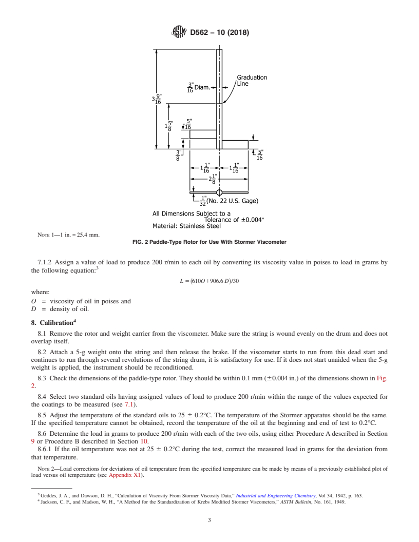
NOTE 1—1 in. = 25.4 mm.
FIG. 2 Paddle-Type Rotor for Use With Stormer Viscometer
7.1.2 Assign a value of load to produce 200 r/min to each oil by converting its viscosity value in poises to load in grams by
the following equation:
L 5 ~610O1906.6 D!/30
where:
O = viscosity of oil in poises and
D = density of oil.
8. Calibration
8.1 Remove the rotor and weight carrier from the viscometer. Make sure the string is wound evenly on the drum and does not
overlap itself.
8.2 Attach a 5-g weight onto the string and then release the brake. If the viscometer starts to run from this dead start and
continues to run through several revolutions of the string drum, it is satisfactory for use. If it does not start unaided when the 5-g
weight is applied, the instrument should be reconditioned.
8.3 Check the dimensions of the paddle-type rotor. They should be within 0.1 mm (60.004 in.) of the dimensions shown in Fig.
2.
8.4 Select two standard oils having assigned values of load to produce 200 r/min within the range of the values expected for
the coatings to be measured (see 7.1).
8.5 Adjust the temperature of the standard oils to 25 6 0.2°C. The temperature of the Stormer apparatus should be the same.
If the specified temperature cannot be obtained, record the temperature of the oil at the beginning and end of test to 0.2°C.
8.6 Determine the load in grams to produce 200 r/min with each of the two oils, using either Procedure A described in Section
9 or Procedure B described in Section 10.
8.6.1 If the oil temperature was not at 25 6 0.2°C during the test, correct the measured load in grams for the deviation from
that temperature.
NOTE 2—Load corrections for deviations of oil temperature from the specified temperature can be made by means of a previously established plot of
load versus oil temperature (see Appendix X1).
Geddes, J. A., and Dawson, D. H., “Calculation of Viscosity From Stormer Viscosity Data,” Industrial and Engineering Chemistry, Vol 34, 1942, p. 163.
Jackson, C. F., and Madson, W. H., “A Method for the Standardization of Krebs Modified Stormer Viscometers,” ASTM Bulletin, No. 161, 1949.
D562 − 10 (2018)
8.7 If the measured load (corrected for any temperature deviation from standard) is within 615 % of the assigned load values
for the oils, the Stormer apparatus can be considered to be in satisfactory calibration.
9. Procedure A (Without Stroboscopic Attachment)
9.1 Thoroughly mix the sample and strain it into a 500-mL (1-pt) container to within 20 mm ( ⁄4 in.) of the top.
9.2 Bring the temperature of the specimen to 25 6 0.2°C and maintain it at that temperature during the test. The temperature
of the Stormer apparatus should be the same.
9.2.1 If the specified temperature cannot be obtained, record the temperature of the specimen at the beginning and end of test
to 0.2°C.
9.3 When the temperature of the specimen has reached equilibrium, stir it vigorously, being careful to avoid entrapping air, and
place the container immediately on the platform of the viscometer so that the paddle-type rotor is immersed in the material to the
mark on the shaft of the rotor.
9.4 Place weights on the hanger of the viscometer and determine a load that will produce 100 revolutions in the range of 25
to 35 s.
9.5 Using the information gained in 9.4, select two loads that will provide two different readings (time to give 100 revolutions)
within the range of 27 to 33 s. Make these measurements from a running start, that is, permit the rotor to make at least 10
revolutions before starting the timing for 100 revolutions.
9.6 Repeat the measurements outlined in 9.5 until two readings for each load are obtained that agree within 0.5 s.
10. Procedure B (With Stroboscopic Timer)
10.1 Follow Procedure A (9.1 – 9.3) for the preparation of the specimen.
10.2 Connect the lamp circuit of the stroboscopic attachment to an electrical power source.
10.3 Place weights on the hanger of the viscometer and determine a load that will produce 100 revolutions in the range from
25 to 35 s.
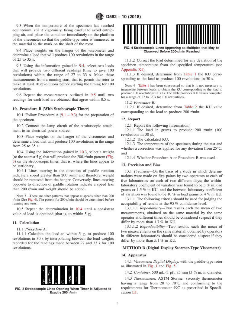
10.4 Using the information gained in 10.3, select a weight (to the nearest 5 g) that will produce the 200-r/min pattern (Fig. 3)
on the stroboscopic timer, that is, where the lines appear to be stationary.
10.4.1 Lines moving in the direction of paddle rotation indicate a speed greater than 200 r/min and therefore, weight should be
removed from the hanger. Conversely, lines moving opposite to direction of paddle rotation indicate a speed less than 200 r/min
and weight should be added.
NOTE 3—There are other patterns that appear at speeds other than 200 r/min (See Fig. 4). The pattern for 200 r/min should be determined before running
any tests.
10.5 Repeat the determination in 10.4 until a consistent value of load is obtained (that is, to within 5 g).
11. Calculation
11.1 Procedure A:
11.1.1 Calculate the load to within 5 g, to produce 100 revolutions in 30 s by interpolating between the load weights recorded
for the readings made between 27 and 33 s for 100 revolutions.
11.1.2 Correct the load determined for any deviation of the specimen temperature from the specified temperature (see Appendix
X1).
11.1.3 If desired, determine from Table 1 the KU corresponding to the load to produce 100 revolutions in 30 s.
NOTE 4—Table 1 has been constructed so that it is not necessary to interpolate between loads to obtain the KU corresponding to the load to produce
100 revolutions in 30 s. The table provides KU values computed for a range of 27 to 33 s for 100 revolutions.
11.2 Procedure B:
11.2.1 If desired, determine from Table 2 the KU value corresponding to the load to produce 200 r/min.
12. Report
12.1 Report the following information:
12.1.1 The load in grams to p
...
Questions, Comments and Discussion
Ask us and Technical Secretary will try to provide an answer. You can facilitate discussion about the standard in here.