


ASTM D5478-13(2018)
(Test Method)Standard Test Methods for Viscosity of Materials by a Falling Needle Viscometer
Standard Test Methods for Viscosity of Materials by a Falling Needle Viscometer
SIGNIFICANCE AND USE
5.1 These test methods are applicable for measuring the rheological properties of varnishes and paints. In particular, the low to moderate shear rate measurements provide information related to sag resistance, leveling, etc.
SCOPE
1.1 These test methods cover the measurement of the viscosity of Newtonian and non-Newtonian liquids. These test methods are applicable to liquids having viscosities in the range from 5 × 10⁻⁴ to 103 Pa·s (0.5 to 106 cP). The shear rate range is dependent upon the needle used and viscosity of the liquid and may vary from 10−4 to 103 s−1. With an extension bar and applied weight, a shear rate of 104 s–1 may be achieved.
1.2 The yield stress of liquids having this property may also be determined.
1.3 These test methods consist of determining liquid viscosities of Newtonian and non-Newtonian fluids (clear or opaque) by measuring the steady-state (constant) or terminal velocities of cylindrical needles as they fall through the test liquid under the influence of gravity. Yield stresses of non-Newtonian liquids may be measured using the same procedure.
1.4 The values stated in SI units are to be regarded as standard. No other units of measurement are included in this standard.
1.5 This standard does not purport to address all of the safety concerns, if any, associated with its use. It is the responsibility of the user of this standard to establish appropriate safety, health, and environmental practices and determine the applicability of regulatory limitations prior to use.
1.6 This international standard was developed in accordance with internationally recognized principles on standardization established in the Decision on Principles for the Development of International Standards, Guides and Recommendations issued by the World Trade Organization Technical Barriers to Trade (TBT) Committee.
General Information
Buy Standard
Standards Content (Sample)
NOTICE: This standard has either been superseded and replaced by a new version or withdrawn.
Contact ASTM International (www.astm.org) for the latest information
Designation: D5478 − 13 (Reapproved 2018)
Standard Test Methods for
Viscosity of Materials by a Falling Needle Viscometer
This standard is issued under the fixed designation D5478; the number immediately following the designation indicates the year of
original adoption or, in the case of revision, the year of last revision.Anumber in parentheses indicates the year of last reapproval.A
superscript epsilon (´) indicates an editorial change since the last revision or reapproval.
1. Scope 2. Referenced Documents
2.1 ASTM Standards:
1.1 These test methods cover the measurement of the
E1Specification for ASTM Liquid-in-Glass Thermometers
viscosity of Newtonian and non-Newtonian liquids. These test
E2251Specification for Liquid-in-Glass ASTM Thermom-
methods are applicable to liquids having viscosities in the
−4 3 6
eters with Low-Hazard Precision Liquids
range from 5×10 to 10 Pa·s (0.5 to 10 cP). The shear rate
range is dependent upon the needle used and viscosity of the
3. Terminology
−4 3 −1
liquid and may vary from 10 to 10 s . With an extension
3.1 Definitions:
4 –1
barandappliedweight,ashearrateof10 s maybeachieved.
3.1.1 dilatant or shear thickening fluid, n—fluid in which
1.2 Theyieldstressofliquidshavingthispropertymayalso the apparent viscosity increases with increasing shear rate.
be determined.
3.1.2 Newtonian fluid, n—fluid in which the dynamic vis-
cosity does not vary with shear rate but only with the
1.3 These test methods consist of determining liquid vis-
temperature and pressure.
cosities of Newtonian and non-Newtonian fluids (clear or
3.1.3 Non-Newtonian fluid, n—fluid in which the dynamic
opaque) by measuring the steady-state (constant) or terminal
viscosity varies with shear rate over at least some shear rate
velocities of cylindrical needles as they fall through the test
range.
liquid under the influence of gravity. Yield stresses of non-
3.1.3.1 Discussion—This viscosity is sometimes referred to
Newtonianliquidsmaybemeasuredusingthesameprocedure.
as the “apparent viscosity” since it is not a true property of the
1.4 The values stated in SI units are to be regarded as
fluid but a variable depending on the shear rate. The viscosity
standard. No other units of measurement are included in this
of most non-Newtonian fluids fits a power law expression. A
standard.
power law fluid is defined by the following equation:
n21
1.5 This standard does not purport to address all of the
η 5 K~dγ/dt! (1)
a
safety concerns, if any, associated with its use. It is the
where:
responsibility of the user of this standard to establish appro-
η = apparentviscosity,Pa·s(ordyne·s/cm =P),mPa·s=
priate safety, health, and environmental practices and deter- a
cP,
mine the applicability of regulatory limitations prior to use.
n n 2
K = fluid consistency, Pa·s (or dyne·s /cm ),
1.6 This international standard was developed in accor-
dγ/dt = shear rate or velocity gradient, 1/s, and
dance with internationally recognized principles on standard-
n = flow behavior index, dimensionless.
ization established in the Decision on Principles for the
3.1.4 pseudoplastic or shear thinning fluid, n—fluid in
Development of International Standards, Guides and Recom-
which the apparent viscosity decreases with increasing shear
mendations issued by the World Trade Organization Technical
rate.
Barriers to Trade (TBT) Committee.
3.1.5 viscosity, n—the ratio between an applied shear stress
to the resulting shear rate (velocity gradient) is defined as the
dynamic viscosity. It is a measure of the resistance to flow of
These test methods are under the jurisdiction of ASTM Committee D01 on
a fluid.
Paint and Related Coatings, Materials, and Applications and are the direct
responsibility of Subcommittee D01.24 on Physical Properties of Liquid Paints &
Paint Materials. For referenced ASTM standards, visit the ASTM website, www.astm.org, or
Current edition approved Sept. 1, 2018. Published September 2018. Originally contact ASTM Customer Service at service@astm.org. For Annual Book of ASTM
approved in 1993. Last previous edition approved in 2013 as published as Standards volume information, refer to the standard’s Document Summary page on
D5478–13. DOI: 10.1520/D5478-13R18. the ASTM website.
*A Summary of Changes section appears at the end of this standard
Copyright © ASTM International, 100 Barr Harbor Drive, PO Box C700, West Conshohocken, PA 19428-2959. United States
D5478 − 13 (2018)
3.1.5.1 Discussion—In the SI unit system, the units of 4.3 Test Method C consists of determining the apparent
viscosity are Pa·s. One mPa·s is equal to one centipoise (cP). viscosity and shear rate of pseudoplastic and dilatant fluids
outside of the power law region.
3.1.6 yield stress, n—some fluids when subjected to a shear
stress behave as deformable solids until a certain critical shear
4.4 Test Method D consists of determining the yield stress
stress (yield stress or yield value) is reached after which they
of liquids that have such a property.
behave as fluids.
5. Significance and Use
3.1.6.1 Discussion—Examples of such fluids include many
paints and pigment pastes and certain food materials such as
5.1 These test methods are applicable for measuring the
ketchup.
rheologicalpropertiesofvarnishesandpaints.Inparticular,the
low to moderate shear rate measurements provide information
4. Summary of Test Methods
related to sag resistance, leveling, etc.
4.1 Test Method A consists of determining the viscosity of
6. Apparatus
Newtonian liquids.
6.1 Viscometer, falling-needle-type and associated equip-
4.2 Test Method B consists of determining the apparent
ment listed as follows:
viscosity and shear rate of pseudoplastic and dilatant fluids in
3,4,5
6.1.1 Falling Needle Viscometer —A schematic of the
the power law region.
falling needle viscometer is shown in Fig. 1. The viscometer
consistsofaverticalcylindricaltestsectionofdiameter D.The
liquidspecimenisplacedinthetestsectionandthespecimen’s
temperature is maintained constant by means of a constant
temperature bath that circulates a liquid through another
cylindrical container (water jacket) that is coaxial to the test
section.Athin hollow cylinder of length L with hemispherical
ends and diameter d (the needle) is aligned with the axis of the
test section and allowed to fall under the influence of gravity.
The needle has a small weight in its forward end that may be
varied to change its density. Another type of needle is con-
nected at the top with an extension bar and a weight holder so
that external weights may be added to increase the effective
density of the needle and the maximum achievable shear rate.
Withanyneedle,terminalvelocityismeasuredbydetermining
the needle transit time between two circumferential marks a
knowndistanceapartonthetestsection(foropaqueliquidsthis
can be done by an automatic sensing device, such as a
magnetic sensor, etc.). With a knowledge of the terminal
velocity, the liquid and needle densities, the geometric con-
stants of the system (L, D, d), the viscosity of a Newtonian
fluid can be calculated from the instrument theory. For a
non-Newtonian fluid whose viscosity depends upon the shear
rate, a series of needles are dropped. The falling needle is an
absolute method of viscosity measurement that does not need
any instrument calibration. However, it may be checked
through use of known certified viscous fluids such as standard
oils.
6.1.2 Thermometer—A thermometric device calibrated to
0.1°Cwhoseaccuracy,precision,andsensitivityareequaltoor
Park, N. A., and Irvine, T. F., Jr., “Measurements of Rheological Fluid
Properties with the Falling Needle Viscometer,” Review of Scientific Instruments,
Vol 59, 1988, pp. 2051–2058.
Park, N. A., and Irvine, T. F., Jr., “The Falling Needle Viscometer, A New
Technique for Viscosity Measurements,” American Laboratory, Vol 20, November
1988, pp. 57–63.
The sole source of supply of the falling needle viscometer known to the
committee at this time is Stony Brook Scientific, Ltd., 914 Fillmore Rd.,
Norristown, PA19403. If you are aware of alternative suppliers, please provide this
information to ASTM International Headquarters. Your comments will receive
careful consideration at a meeting of the responsible technical committee, which
you may attend. This instrument may be interfaced with a computer for data
collection and analysis. A computer program is available for data analysis for
FIG. 1 Schematic of Falling Needle Viscometer instruments that are not interfaced.
D5478 − 13 (2018)
TABLE 1 Geometric Constants (G) for Several System
betterthantheASTMthermometersdescribedinSpecifications
A
Diameters (D) and Needle Lengths (L)
E1 or E2251. The use of non-mercury thermometers or other
System Diameter, Needle Length, G, Viscosity Range,
devices is highly recommended.
cm cm 1/cm mPa·s (= cP)
6.1.3 Circulating Liquid Bath, capable of maintaining the 6
1.905 10.2 80.89 50–10
0.8044 4.2 529.8 10–10
test specimen temperature to 60.1°C.
0.4996 4.2 12,816 0.5–20
6.1.4 Stopwatch or Electronic Device,capableofmeasuring
A
Needle diameter = 0.3980 cm.
to 60.01 s or an automatic sensing device with the same
accuracy.
7. Preparation of Specimen
where:
7.1 After opening the specimen container, mix the fluid
η = dynamic viscosity, mPa·s (= cP),
gently with a glass rod for 5 min.
g = local acceleration of gravity, cm/s ,
ρ = needle density, g/cm ,
s
7.2 Pourthespecimencarefullyintothetestsectionsoasto
ρ = test specimen density, g/cm ,
l
minimizetheformationofairbubbles.Ifavailable,asyringeis
U = measured needle terminal velocity, cm/s, and
t
useful for this purpose.
G = geometric constant depending upon the test section and
7.3 Remix the specimen in the test container using the needle dimensions D, L, and d that is furnished by the
instrument manufacturer. Table 1 lists several typical
needle retriever rod by pushing it up and down four times at a
velocity of approximately 4 cm/s. geometric constants.
7.4 Allow the specimen to remain at rest in the test section
10. Report
for a minimum of 5 min or until any air bubbles have risen to
10.1 Report the following information:
the surface. Longer rest times may be used in the case of yield
10.1.1 Name of the test specimen,
stress measurements.
10.1.2 Temperature of the test specimen, °C, and
TEST METHOD A—NEWTONIAN FLUIDS 10.1.3 Viscosityofthetestspecimen,mPa·s(=cP)(Note1).
VISCOSITY MEASUREMENTS
NOTE 1—If the same needle is dropped more than once, report the
minimum, maximum, and average viscosity values. If needles of different
8. Procedure densities are dropped, report the individual viscosity measurements.
8.1 Level the viscometer so that the central vertical axis of
11. Precision and Bias
the test section is parallel to the gravity vector by using either
11.1 Precision—In an interlaboratory study, six operators in
a bubble level or a plumb bob.
six laboratories measured (four replicates) viscosities of three
8.2 Circulate the liquid from the constant temperature bath
Newtonian oils and one essentially Newtonian spar varnish.
until the test specimen temperature is constant at the specified
Thesematerialscoveredaviscosityrangeof100to1440mPa·s
value with a variation of 60.1°C.
(cP). The within-laboratory coefficient of variation was found
tobe2.70or0.5%oftheaverageviscosity.Thecorresponding
8.3 To determine the viscosity, drop a needle along the
between-laboratories coefficient was 4.58 or 0.9% of the
central axis of the test section and measure its velocity by the
average viscosity. Based on these coefficients, the following
amountoftimetakentomovebetweentwoofthemeasurement
criteria should be used for judging the acceptability of results
lines. This may be done by using a stopwatch or an automatic
at the 95% confidence level:
sensingdevice.Themeasurementlinesshouldbeatleastatest
11.1.1 Repeatability—Two results of individual viscosity
section diameter from the top and bottom of the liquid.
measurements obtained by the same operator at different times
8.4 Record the values of the needle velocity, the liquid and
should be considered suspect if they differ by more than 1.4%
needle densities, the test specimen temperature, the local
relative.
acceleration of gravity and the test section, and needle dimen-
11.1.2 Reproducibility—Two results of individual viscosity
sions D, L, and d.
measurements obtained by operators in different laboratories
should be considered suspect if they differ by more than 2.4%
8.5 Drop additional needles of different densities to estab-
relative.
lish whether the fluid is Newtonian. If the measured viscosity
is essentially constant using the different density needles, then 11.2 Bias—Bias has not been determined for this test
method.
the fluid is Newtonian.
TEST METHOD B—APPARENT VISCOSITY AND
9. Calculation
SHEAR RATE OF PSEUDOPLASTIC AND DILATANT
9.1 Calculate the Newtonian fluid viscosity for any needle
FLUIDS IN POWER LAW REGIONS
drop as follows:
12. Procedure
g~ρ 2 ρ !
s l
η 5 (2)
U G 12.1 Follow the procedures in accordance with 8.1 and 8.2.
t
D5478 − 13 (2018)
12.2 Drop a series of needles of the same geometry but 14.1.5 Flow curve (graph) of apparent viscosity η versus γ˙
a
different densities along the central axis of the test section and in Log-Log coordinates including the temperature and test
measure their velocities by the amount of time taken to travel specimen information.
between two of the measurement lines. This may be done by
15. Precision and Bias
using a stopwatch or an automatic sensing device. The mea-
15.1 Precision—In an interlaboratory study, six operators in
surement lines should be at least a test section diameter from
six laboratories measured (four replicates) viscosities of four
the top and bottom of the liquid.
materials comprising a spar varnish, a rust inhibitive primer, a
12.3 Record the values of the needle velocities, needle
latex semigloss, and an alkyd gloss enamel, that covered a
densities, the test specimen temperature, the local acceleration
reasonable range of viscosities. The varnish was very slightly
ofgravityandthetestsection,andneedledimensions D, L,and
dilatant (shear thickening) and the paints all were shear
d.
thinning. Measurements were taken with at least three needles
in each case and as many as six (equivalent to six operators
13. Calculation
testing 18 paints). Because Test Method B does not require
13.1 Plot a graph of Log (ρ − ρ) versus Log U.Ifthe
e s l e t single point viscosities, but rather viscosity-shear rate curves,
points form a straight line then the shear rate is in the power
and slight differences in specified needles give different shear
law region (see 13.3) and the slope of the straight line is the
rates and, therefore, vis
...
This document is not an ASTM standard and is intended only to provide the user of an ASTM standard an indication of what changes have been made to the previous version. Because
it may not be technically possible to adequately depict all changes accurately, ASTM recommends that users consult prior editions as appropriate. In all cases only the current version
of the standard as published by ASTM is to be considered the official document.
Designation: D5478 − 13 D5478 − 13 (Reapproved 2018)
Standard Test Methods for
Viscosity of Materials by a Falling Needle Viscometer
This standard is issued under the fixed designation D5478; the number immediately following the designation indicates the year of
original adoption or, in the case of revision, the year of last revision. A number in parentheses indicates the year of last reapproval. A
superscript epsilon (´) indicates an editorial change since the last revision or reapproval.
1. Scope*Scope
1.1 These test methods cover the measurement of the viscosity of Newtonian and non-Newtonian liquids. These test methods
−4 3 6
are applicable to liquids having viscosities in the range from 5 × 10 to 10 Pa·s (0.5 to 10 cP). The shear rate range is dependent
−4 3 −1
upon the needle used and viscosity of the liquid and may vary from 10 to 10 s . With an extension bar and applied weight,
4 –1
a shear rate of 10 s may be achieved.
1.2 The yield stress of liquids having this property may also be determined.
1.3 These test methods consist of determining liquid viscosities of Newtonian and non-Newtonian fluids (clear or opaque) by
measuring the steady-state (constant) or terminal velocities of cylindrical needles as they fall through the test liquid under the
influence of gravity. Yield stresses of non-Newtonian liquids may be measured using the same procedure.
1.4 The values stated in SI units are to be regarded as standard. No other units of measurement are included in this standard.
1.5 This standard does not purport to address all of the safety concerns, if any, associated with its use. It is the responsibility
of the user of this standard to establish appropriate safety safety, health, and healthenvironmental practices and determine the
applicability of regulatory limitations prior to use.
1.6 This international standard was developed in accordance with internationally recognized principles on standardization
established in the Decision on Principles for the Development of International Standards, Guides and Recommendations issued
by the World Trade Organization Technical Barriers to Trade (TBT) Committee.
2. Referenced Documents
2.1 ASTM Standards:
E1 Specification for ASTM Liquid-in-Glass Thermometers
E2251 Specification for Liquid-in-Glass ASTM Thermometers with Low-Hazard Precision Liquids
3. Terminology
3.1 Definitions:
3.1.1 dilatant or shear thickening fluid, n—fluid in which the apparent viscosity increases with increasing shear rate.
3.1.2 Newtonian fluid, n—fluid in which the dynamic viscosity does not vary with shear rate but only with the temperature and
pressure.
3.1.3 Non-Newtonian fluid, n—fluid in which the dynamic viscosity varies with shear rate over at least some shear rate range.
3.1.3.1 Discussion—
This viscosity is sometimes referred to as the “apparent viscosity” since it is not a true property of the fluid but a variable depending
on the shear rate. The viscosity of most non-Newtonian fluids fits a power law expression. A power law fluid is defined by the
following equation:
n21
η 5 K dγ/dt (1)
~ !
a
These test methods are under the jurisdiction of ASTM Committee D01 on Paint and Related Coatings, Materials, and Applications and are the direct responsibility of
Subcommittee D01.24 on Physical Properties of Liquid Paints and& Paint Materials.
Current edition approved Feb. 1, 2013Sept. 1, 2018. Published February 2013September 2018. Originally approved in 1993. Last previous edition approved in 20092013
as published as D5478 – 09.D5478 – 13. DOI: 10.1520/D5478-13.10.1520/D5478-13R18.
For referenced ASTM standards, visit the ASTM website, www.astm.org, or contact ASTM Customer Service at service@astm.org. For Annual Book of ASTM Standards
volume information, refer to the standard’sstandard’s Document Summary page on the ASTM website.
*A Summary of Changes section appears at the end of this standard
Copyright © ASTM International, 100 Barr Harbor Drive, PO Box C700, West Conshohocken, PA 19428-2959. United States
D5478 − 13 (2018)
where:
η = apparent viscosity, Pa·s (or dyne·s/cm = P), mPa·s = cP,
a
n n 2
K = fluid consistency, Pa·s (or dyne·s /cm ),
dγ/dt = shear rate or velocity gradient, 1/s, and
n = flow behavior index, dimensionless.
3.1.4 pseudoplastic or shear thinning fluid, n—fluid in which the apparent viscosity decreases with increasing shear rate.
3.1.5 viscosity, n—the ratio between an applied shear stress to the resulting shear rate (velocity gradient) is defined as the
dynamic viscosity. It is a measure of the resistance to flow of a fluid.
3.1.5.1 Discussion—
In the SI unit system, the units of viscosity are Pa·s. One mPa·s is equal to one centipoise (cP).
3.1.6 yield stress, n—some fluids when subjected to a shear stress behave as deformable solids until a certain critical shear stress
(yield stress or yield value) is reached after which they behave as fluids.
3.1.6.1 Discussion—
Examples of such fluids include many paints and pigment pastes and certain food materials such as ketchup.
4. Summary of Test Methods
4.1 Test Method A consists of determining the viscosity of Newtonian liquids.
4.2 Test Method B consists of determining the apparent viscosity and shear rate of pseudoplastic and dilatant fluids in the power
law region.
4.3 Test Method C consists of determining the apparent viscosity and shear rate of pseudoplastic and dilatant fluids outside of
the power law region.
4.4 Test Method D consists of determining the yield stress of liquids that have such a property.
5. Significance and Use
5.1 These test methods are applicable for measuring the rheological properties of varnishes and paints. In particular, the low to
moderate shear rate measurements provide information related to sag resistance, leveling, etc.
6. Apparatus
6.1 Viscometer, falling-needle-type and associated equipment listed as follows:
3,4,5
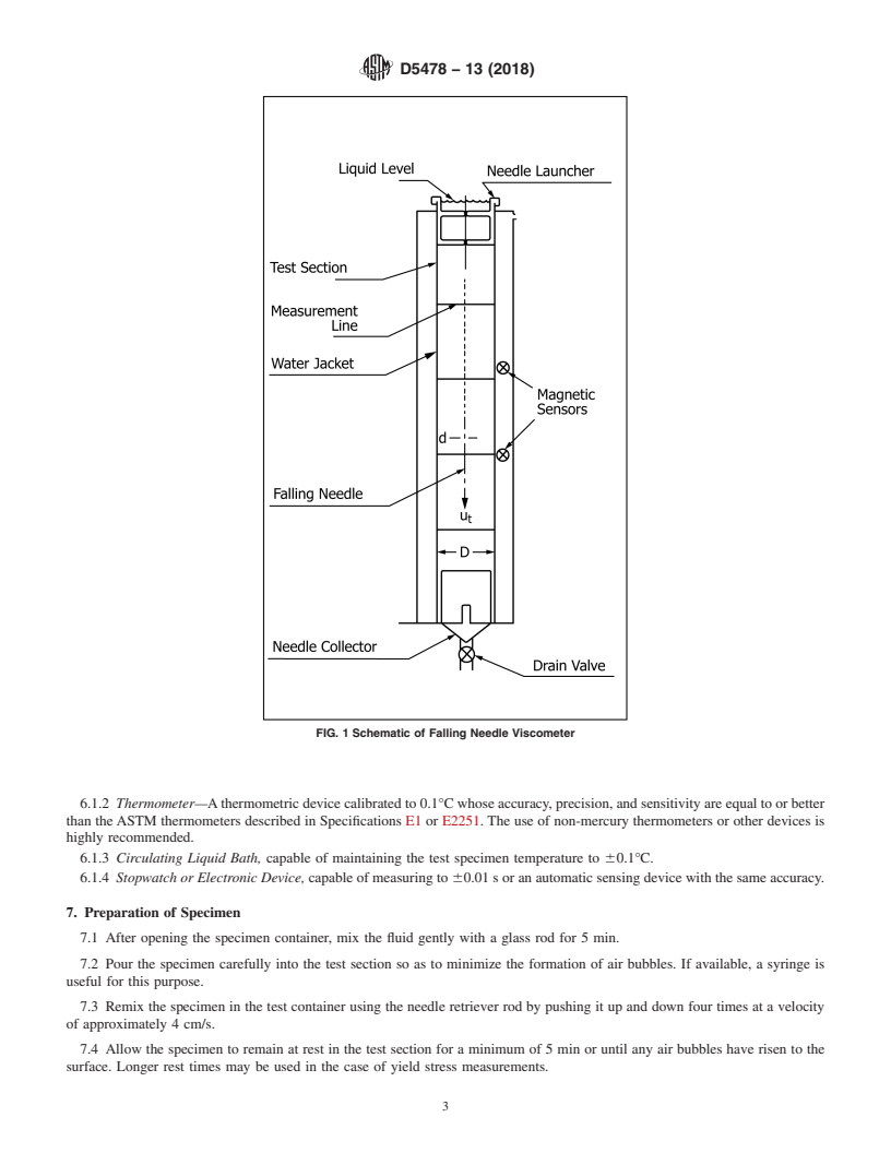
6.1.1 Falling Needle Viscometer —A schematic of the falling needle viscometer is shown in Fig. 1. The viscometer consists
of a vertical cylindrical test section of diameter D. The liquid specimen is placed in the test section and the specimen’s temperature
is maintained constant by means of a constant temperature bath that circulates a liquid through another cylindrical container (water
jacket) that is coaxial to the test section. A thin hollow cylinder of length L with hemispherical ends and diameter d (the needle)
is aligned with the axis of the test section and allowed to fall under the influence of gravity. The needle has a small weight in its
forward end that may be varied to change its density. Another type of needle is connected at the top with an extension bar and a
weight holder so that external weights may be added to increase the effective density of the needle and the maximum achievable
shear rate. With any needle, terminal velocity is measured by determining the needle transit time between two circumferential
marks a known distance apart on the test section (for opaque liquids this can be done by an automatic sensing device, such as a
magnetic sensor, etc.). With a knowledge of the terminal velocity, the liquid and needle densities, the geometric constants of the
system (L, D, d), the viscosity of a Newtonian fluid can be calculated from the instrument theory. For a non-Newtonian fluid whose
viscosity depends upon the shear rate, a series of needles are dropped. The falling needle is an absolute method of viscosity
measurement that does not need any instrument calibration. However, it may be checked through use of known certified viscous
fluids such as standard oils.
Park, N. A., and Irvine, T. F., Jr., “Measurements of Rheological Fluid Properties with the Falling Needle Viscometer,” Review of Scientific Instruments, Vol 59, 1988,
pp. 2051–2058.
Park, N. A., and Irvine, T. F., Jr., “The Falling Needle Viscometer, A New Technique for Viscosity Measurements,” American Laboratory, Vol 20, November 1988, pp.
57–63.
The sole source of supply of the falling needle viscometer known to the committee at this time is Stony Brook Scientific, Ltd., 914 Fillmore Rd., Norristown, PA 19403.
If you are aware of alternative suppliers, please provide this information to ASTM International Headquarters. Your comments will receive careful consideration at a meeting
of the responsible technical committee, which you may attend. This instrument may be interfaced with a computer for data collection and analysis. A computer program is
available for data analysis for instruments that are not interfaced.
D5478 − 13 (2018)
FIG. 1 Schematic of Falling Needle Viscometer
6.1.2 Thermometer—A thermometric device calibrated to 0.1°C whose accuracy, precision, and sensitivity are equal to or better
than the ASTM thermometers described in Specifications E1 or E2251. The use of non-mercury thermometers or other devices is
highly recommended.
6.1.3 Circulating Liquid Bath, capable of maintaining the test specimen temperature to 60.1°C.
6.1.4 Stopwatch or Electronic Device, capable of measuring to 60.01 s or an automatic sensing device with the same accuracy.
7. Preparation of Specimen
7.1 After opening the specimen container, mix the fluid gently with a glass rod for 5 min.
7.2 Pour the specimen carefully into the test section so as to minimize the formation of air bubbles. If available, a syringe is
useful for this purpose.
7.3 Remix the specimen in the test container using the needle retriever rod by pushing it up and down four times at a velocity
of approximately 4 cm/s.
7.4 Allow the specimen to remain at rest in the test section for a minimum of 5 min or until any air bubbles have risen to the
surface. Longer rest times may be used in the case of yield stress measurements.
D5478 − 13 (2018)
TEST METHOD A—NEWTONIAN FLUIDS VISCOSITY MEASUREMENTS
8. Procedure
8.1 Level the viscometer so that the central vertical axis of the test section is parallel to the gravity vector by using either a
bubble level or a plumb bob.
8.2 Circulate the liquid from the constant temperature bath until the test specimen temperature is constant at the specified value
with a variation of 60.1°C.
8.3 To determine the viscosity, drop a needle along the central axis of the test section and measure its velocity by the amount
of time taken to move between two of the measurement lines. This may be done by using a stopwatch or an automatic sensing
device. The measurement lines should be at least a test section diameter from the top and bottom of the liquid.
8.4 Record the values of the needle velocity, the liquid and needle densities, the test specimen temperature, the local acceleration
of gravity and the test section, and needle dimensions D, L, and d.
8.5 Drop additional needles of different densities to establish whether the fluid is Newtonian. If the measured viscosity is
essentially constant using the different density needles, then the fluid is Newtonian.
9. Calculation
9.1 Calculate the Newtonian fluid viscosity for any needle drop as follows:
g ρ 2 ρ
~ !
s l
η5 (2)
U G
t
where:
η = dynamic viscosity, mPa·s (= cP),
g = local acceleration of gravity, cm/s ,
ρ = needle density, g/cm ,
s
ρ = test specimen density, g/cm ,
l
U = measured needle terminal velocity, cm/s, and
t
G = geometric constant depending upon the test section and needle dimensions D,L, and d that is furnished by the instrument
manufacturer. Table 1 lists several typical geometric constants.
10. Report
10.1 Report the following information:
10.1.1 Name of the test specimen,
10.1.2 Temperature of the test specimen, °C, and
10.1.3 Viscosity of the test specimen, mPa·s (= cP) (Note 1).
NOTE 1—If the same needle is dropped more than once, report the minimum, maximum, and average viscosity values. If needles of different densities
are dropped, report the individual viscosity measurements.
11. Precision and Bias
11.1 Precision—In an interlaboratory study, six operators in six laboratories measured (four replicates) viscosities of three
Newtonian oils and one essentially Newtonian spar varnish. These materials covered a viscosity range of 100 to 1440 mPa·s (cP).
The within-laboratory coefficient of variation was found to be 2.70 or 0.5 % of the average viscosity. The corresponding
between-laboratories coefficient was 4.58 or 0.9 % of the average viscosity. Based on these coefficients, the following criteria
should be used for judging the acceptability of results at the 95 % confidence level:
11.1.1 Repeatability—Two results of individual viscosity measurements obtained by the same operator at different times should
be considered suspect if they differ by more than 1.4 % relative.
11.1.2 Reproducibility—Two results of individual viscosity measurements obtained by operators in different laboratories should
be considered suspect if they differ by more than 2.4 % relative.
11.2 Bias—Bias has not been determined for this test method.
TABLE 1 Geometric Constants (G) for Several System
A
Diameters (D) and Needle Lengths (L)
System Diameter, Needle Length, G, Viscosity Range,
cm cm 1/cm mPa·s (= cP)
1.905 10.2 80.89 50–10
0.8044 4.2 529.8 10–10
0.4996 4.2 12,816 0.5–20
A
Needle diameter = 0.3980 cm.
D5478 − 13 (2018)
TEST METHOD B—APPARENT VISCOSITY AND SHEAR RATE OF PSEUDOPLASTIC AND DILATANT FLUIDS
IN POWER LAW REGIONS
12. Procedure
12.1 Follow the procedures in accordance with 8.1 and 8.2.
12.2 Drop a series of needles of the same geometry but different densities along the central axis of the test section and measure
their velocities by the amount of time taken to travel between two of the measurement lines. This may be done by using a stopwatch
or an automatic sensing device. The measurement lines should be at least a test section diameter from the top and bottom of the
liquid.
12.3 Record the values of the needle velocities, needle densities, the test specimen temperature, the local acceleration of gravity
and the test section, and needle dimensions D, L, and d.
13. Calculation
13.1 Plot a graph of Log (ρ − ρ ) versus Log U . If the points form a straight line then the shear rate is in the power law region
e s l e t
(see 13.3) and the slope of the straight line is the flow index, n.
13.2 Calculate the shear rate γ˙ from the following equation:
Log ˙γ/U 5 A 1B Log n1C Log n (3)
~ ! ~ !
e t 1 1 e 1 e
3 4 5
1D Log n 1E Log n 1F Log n
~ ! ~ ! ~ !
1 e 1 e 1 e
where the values of A , B , C , D , E , and F are
...
Questions, Comments and Discussion
Ask us and Technical Secretary will try to provide an answer. You can facilitate discussion about the standard in here.