

ASTM D6557-18e1
(Test Method)Standard Test Method for Evaluation of Rust Preventive Characteristics of Automotive Engine Oils
General Information
- Abstract
SIGNIFICANCE AND USE
5.1 This bench test method was designed as a replacement for Test Method D5844. Test Method D5844 was designed to measure the ability of an engine oil to protect valve train components against rusting or corrosion under low temperature, short-trip service, and was correlated with vehicles in that type of service prior to 1978.5
5.1.1 Correlation between these two test methods has been demonstrated for most, but not all, of the test oils evaluated.
SCOPE
1.1 This test method covers a Ball Rust Test (BRT) procedure for evaluating the anti-rust ability of fluid lubricants. The procedure is particularly suitable for the evaluation of automotive engine oils under low-temperature, acidic service conditions.
1.2 The values stated in SI units are to be regarded as standard. The values given in parentheses after SI units are provided for information only and are not considered standard.
1.2.1 Exceptions—Where there is no direct equivalent, such as the units for screw threads, national pipe threads/diameters, and tubing size.
1.3 This standard does not purport to address all of the safety concerns, if any, associated with its use. It is the responsibility of the user of this standard to establish appropriate safety, health, and environmental practices and determine the applicability of regulatory limitations prior to use. See 7.1.1 – 7.1.3 and 8.2.1.1.
1.4 This international standard was developed in accordance with internationally recognized principles on standardization established in the Decision on Principles for the Development of International Standards, Guides and Recommendations issued by the World Trade Organization Technical Barriers to Trade (TBT) Committee.
- Status
- Published
- Publication Date
- 30-Sep-2018
- Technical Committee
- D02 - Petroleum Products, Liquid Fuels, and Lubricants
- Drafting Committee
- D02.B0.07 - Development and Surveillance of Bench Tests Methods
Overview
ASTM D6557-18e1 – Standard Test Method for Evaluation of Rust Preventive Characteristics of Automotive Engine Oils – establishes a reliable laboratory procedure for assessing the anti-rust properties of automotive engine oils. Developed by ASTM International, this standard is specifically tailored for evaluating engine lubricants under low-temperature, acidic service conditions using the Ball Rust Test (BRT) method. This test is a fundamental tool for oil manufacturers, testing laboratories, and regulatory compliance, ensuring that engine oils provide adequate protection against corrosion, particularly in challenging operational environments.
Key Topics
- Ball Rust Test (BRT) Procedure: The core of ASTM D6557-18e1 is the BRT method, which examines the ability of fluid lubricants, notably engine oils, to protect metal components from rust. This is crucial for determining oil performance in scenarios where vehicles are subjected to frequent short trips and cold starts.
- Significance and Correlation: This method was developed as a modern alternative to the previous Test Method D5844, maintaining proven correlation for most test oils. It remains a critical quality indicator for engine oils, especially for applications corresponding to low-temperature and acidic operating conditions.
- Calibration and Reference Oils: The standard emphasizes the importance of using calibrated test equipment and reference oils to ensure reproducibility and reliability of results. Organizations such as the ASTM Test Monitoring Center (TMC), American Petroleum Institute (API), and the American Chemistry Council require laboratories to participate in TMC services for standardized test outputs.
- Precision, Reporting, and Bias: ASTM D6557-18e1 outlines detailed procedures for reporting results, including statistical measures of reproducibility and precision, providing confidence in data consistency across different laboratories.
- Safety and International Integration: The standard stresses appropriate safety, health, and environmental practices, ensuring global applicability by adhering to the WTO Technical Barriers to Trade (TBT) principles.
Applications
The ASTM D6557-18e1 standard is widely used in several key areas in the lubrication and automotive industries:
- Engine Oil Formulation: Oil manufacturers utilize this method to develop and validate products with enhanced rust preventive characteristics, especially for modern engines experiencing harsh service conditions.
- Quality Assurance: Laboratories and quality control teams implement this test to confirm batch-to-batch oil performance, ensuring compliance with internal and industry standards.
- Specification Qualification: Automotive manufacturers and oil marketers rely on ASTM D6557-18e1 test results when qualifying lubricants for service fill or aftermarket sales.
- Regulatory and Certification Programs: Participation in monitoring programs such as those managed by ASTM TMC is often mandatory for certification with organizations like API and SAE.
- Field Service Correlation: The test method serves as a laboratory predictor for in-service rust prevention performance, aiding in warranty documentation and performance guarantees.
Related Standards
For comprehensive evaluation and integration, reference the following associated ASTM standards:
- ASTM D5844 (withdrawn): The predecessor rust inhibition test this method replaces.
- ASTM D4175: Terminology relating to petroleum products, liquid fuels, and lubricants; provides definitions supportive to D6557-18e1.
- ASTM E29: Practice for using significant digits in test data to determine specification conformance; mandate for reporting precision.
By adhering to ASTM D6557-18e1, organizations can confidently assess and benchmark the rust preventive performance of engine oils, ensuring long-term protection of sensitive engine components and compliance with industry best practices. This standard is essential for anyone engaged in the development, testing, or certification of automotive lubricants.
Relations
- Refers
ASTM D4175-23a - Standard Terminology Relating to Petroleum Products, Liquid Fuels, and Lubricants - Effective Date
- 15-Dec-2023
- Refers
ASTM D4175-23e1 - Standard Terminology Relating to Petroleum Products, Liquid Fuels, and Lubricants - Effective Date
- 01-Jul-2023
- Effective Date
- 01-Oct-2008
- Effective Date
- 15-Nov-2006
- Effective Date
- 15-Sep-2006
- Effective Date
- 01-May-2006
- Effective Date
- 01-Dec-2004
- Effective Date
- 10-May-2002
- Effective Date
- 10-May-1999
Get Certified
Connect with accredited certification bodies for this standard

Element Materials Technology
Materials testing and product certification.

ABS Group Brazil
ABS Group certification services in Brazil.

ABS Quality Evaluations Inc.
American Bureau of Shipping quality certification.
Sponsored listings
Frequently Asked Questions
ASTM D6557-18e1 is a standard published by ASTM International. Its full title is "Standard Test Method for Evaluation of Rust Preventive Characteristics of Automotive Engine Oils". This standard covers: SIGNIFICANCE AND USE 5.1 This bench test method was designed as a replacement for Test Method D5844. Test Method D5844 was designed to measure the ability of an engine oil to protect valve train components against rusting or corrosion under low temperature, short-trip service, and was correlated with vehicles in that type of service prior to 1978.5 5.1.1 Correlation between these two test methods has been demonstrated for most, but not all, of the test oils evaluated. SCOPE 1.1 This test method covers a Ball Rust Test (BRT) procedure for evaluating the anti-rust ability of fluid lubricants. The procedure is particularly suitable for the evaluation of automotive engine oils under low-temperature, acidic service conditions. 1.2 The values stated in SI units are to be regarded as standard. The values given in parentheses after SI units are provided for information only and are not considered standard. 1.2.1 Exceptions—Where there is no direct equivalent, such as the units for screw threads, national pipe threads/diameters, and tubing size. 1.3 This standard does not purport to address all of the safety concerns, if any, associated with its use. It is the responsibility of the user of this standard to establish appropriate safety, health, and environmental practices and determine the applicability of regulatory limitations prior to use. See 7.1.1 – 7.1.3 and 8.2.1.1. 1.4 This international standard was developed in accordance with internationally recognized principles on standardization established in the Decision on Principles for the Development of International Standards, Guides and Recommendations issued by the World Trade Organization Technical Barriers to Trade (TBT) Committee.
SIGNIFICANCE AND USE 5.1 This bench test method was designed as a replacement for Test Method D5844. Test Method D5844 was designed to measure the ability of an engine oil to protect valve train components against rusting or corrosion under low temperature, short-trip service, and was correlated with vehicles in that type of service prior to 1978.5 5.1.1 Correlation between these two test methods has been demonstrated for most, but not all, of the test oils evaluated. SCOPE 1.1 This test method covers a Ball Rust Test (BRT) procedure for evaluating the anti-rust ability of fluid lubricants. The procedure is particularly suitable for the evaluation of automotive engine oils under low-temperature, acidic service conditions. 1.2 The values stated in SI units are to be regarded as standard. The values given in parentheses after SI units are provided for information only and are not considered standard. 1.2.1 Exceptions—Where there is no direct equivalent, such as the units for screw threads, national pipe threads/diameters, and tubing size. 1.3 This standard does not purport to address all of the safety concerns, if any, associated with its use. It is the responsibility of the user of this standard to establish appropriate safety, health, and environmental practices and determine the applicability of regulatory limitations prior to use. See 7.1.1 – 7.1.3 and 8.2.1.1. 1.4 This international standard was developed in accordance with internationally recognized principles on standardization established in the Decision on Principles for the Development of International Standards, Guides and Recommendations issued by the World Trade Organization Technical Barriers to Trade (TBT) Committee.
ASTM D6557-18e1 is classified under the following ICS (International Classification for Standards) categories: 75.100 - Lubricants, industrial oils and related products. The ICS classification helps identify the subject area and facilitates finding related standards.
ASTM D6557-18e1 has the following relationships with other standards: It is inter standard links to ASTM D4175-23a, ASTM D4175-23e1, ASTM E29-08, ASTM E29-06b, ASTM E29-06a, ASTM E29-06, ASTM E29-04, ASTM E29-02e1, ASTM E29-93a(1999). Understanding these relationships helps ensure you are using the most current and applicable version of the standard.
ASTM D6557-18e1 is available in PDF format for immediate download after purchase. The document can be added to your cart and obtained through the secure checkout process. Digital delivery ensures instant access to the complete standard document.
Standards Content (Sample)
This international standard was developed in accordance with internationally recognized principles on standardization established in the Decision on Principles for the
Development of International Standards, Guides and Recommendations issued by the World Trade Organization Technical Barriers to Trade (TBT) Committee.
´1
Designation: D6557 − 18
Standard Test Method for
Evaluation of Rust Preventive Characteristics of Automotive
Engine Oils
This standard is issued under the fixed designation D6557; the number immediately following the designation indicates the year of
original adoption or, in the case of revision, the year of last revision.Anumber in parentheses indicates the year of last reapproval.A
superscript epsilon (´) indicates an editorial change since the last revision or reapproval.
ε NOTE—Editorially updated TMC governance information in June 2022.
INTRODUCTION
Portions of this test method are written for use by laboratories that make use of ASTM Test
Monitoring Center (TMC) services (see Annex A4 to Annex A7).
TheTMCprovidesreferenceoils,andengineeringandstatisticalservicestolaboratoriesthatdesire
to produce test results that are statistically similar to those produced by laboratories previously
calibrated by the TMC.
In general, the test purchaser decides if a calibrated test stand is to be used. Organizations such as
theAmericanChemistryCouncilrequirethatalaboratoryutilizetheTMCservicesaspartoftheirtest
registration process. In addition, the American Petroleum Institute and the Gear Lubricant Review
Committee of the Lubricant Review Institute (SAE International) require that a laboratory use the
TMC services in seeking qualification of oils against their specifications.
The advantage of using the TMC services to calibrate test stands is that the test laboratory (and
hence the test purchaser) has an assurance that the test stand was operating at the proper level of test
severity. It should also be borne in mind that results obtained in a non-calibrated test stand may not
be the same as those obtained in a test stand participating in the ASTM TMC services process.
ASTM International policy is to encourage the development of test procedures based on generic
equipment. It is recognized that there are occasions where critical/sole-source equipment has been
approved by the technical committee (surveillance panel/task force) and is required by the test
procedure. The technical committee that oversees the test procedure is encouraged to clearly identify
if the part is considered critical in the test procedure. If a part is deemed to be critical, ASTM
encouragesalternativesupplierstobegiventheopportunityforconsiderationofsupplyingthecritical
part/component providing they meet the approval process set forth by the technical committee
An alternative supplier can start the process by initiating contact with the technical committee
(current chairs shown onASTM TMC website). The supplier should advise on the details of the part
that is intended to be supplied. The technical committee will review the request and determine
feasibility of an alternative supplier for the requested replacement critical part. In the event that a
replacement critical part has been identified and proven equivalent the sole-source supplier footnote
shall be removed from the test procedure.
1. Scope* procedure is particularly suitable for the evaluation of automo-
tive engine oils under low-temperature, acidic service condi-
1.1 This test method covers a Ball Rust Test (BRT) proce-
tions.
dure for evaluating the anti-rust ability of fluid lubricants. The
This test method is under the jurisdiction of ASTM Committee D02 on
Petroleum Products, Liquid Fuels, and Lubricants and is the direct responsibility of Until the next revision of this test method, the ASTM Test Monitoring Center
Subcommittee D02.B0.07 on Development and Surveillance of Bench Tests will update changes in the test method by means of information letters. Information
Methods. letters may be obtained from the ASTM Test Monitoring Center, 203 Armstrong
Current edition approved Oct. 1, 2018. Published October 2018. Originally Drive,Freeport,PA16229.ThistestmethodissupplementedbyInformationLetters
approved in 2000. Last previous edition approved in 2013 as D6557–13. DOI: and Memoranda issued by the ASTM TMC. This edition incorporates revisions in
10.1520/D6557-18E01. all Information Letters through No. 18-1.
*A Summary of Changes section appears at the end of this standard
Copyright © ASTM International, 100 Barr Harbor Drive, PO Box C700, West Conshohocken, PA 19428-2959. United States
´1
D6557 − 18
1.2 The values stated in SI units are to be regarded as 3.1.6 test oil, n—any oil subjected to evaluation in an
standard. The values given in parentheses after SI units are established procedure.
providedforinformationonlyandarenotconsideredstandard.
3.2 Definitions of Terms Specific to This Standard:
1.2.1 Exceptions—Where there is no direct equivalent, such
3.2.1 average gray value (AGV),n—measurement of
as the units for screw threads, national pipe threads/diameters,
brightnessunitsontestspecimens,indicatingthedegreeofrust
and tubing size.
protection.
1.3 This standard does not purport to address all of the
3.2.2 specimen, n—acarbonsteelball,5.6mm(AISI1040).
safety concerns, if any, associated with its use. It is the
responsibility of the user of this standard to establish appro- 4. Summary of Test Method
priate safety, health, and environmental practices and deter-
4.1 Multiple test tubes, each containing test oil and a
mine the applicability of regulatory limitations prior to use.
specimen, are placed in a test tube rack that is attached to a
See 7.1.1 – 7.1.3 and 8.2.1.1.
mechanical shaker. The shaker speed and temperature are
1.4 This international standard was developed in accor-
controlled.
dance with internationally recognized principles on standard-
4.2 Airandanacidicsolutionarecontinuouslyfedintoeach
ization established in the Decision on Principles for the
testtubeoveran18hperiodtocreateacorrosiveenvironment.
Development of International Standards, Guides and Recom-
mendations issued by the World Trade Organization Technical 4.3 The specimens are then removed, rinsed, and analyzed
Barriers to Trade (TBT) Committee.
by an optical imaging system designed to quantify the antirust
capability of each test oil.
2. Referenced Documents
5. Significance and Use
2.1 ASTM Standards:
5.1 This bench test method was designed as a replacement
D4175Terminology Relating to Petroleum Products, Liquid
for Test Method D5844. Test Method D5844 was designed to
Fuels, and Lubricants
measure the ability of an engine oil to protect valve train
D5844Test Method for Evaluation of Automotive Engine
components against rusting or corrosion under low
Oils for Inhibition of Rusting (Sequence IID) (Withdrawn
temperature, short-trip service, and was correlated with ve-
2003)
hicles in that type of service prior to 1978.
E29Practice for Using Significant Digits in Test Data to
5.1.1 Correlation between these two test methods has been
Determine Conformance with Specifications
demonstrated for most, but not all, of the test oils evaluated.
3. Terminology
6. Apparatus
3.1 Definitions:
6.1 Specimen Preparation System—Obtain the specimens
3.1.1 calibrate, v—todeterminetheindicationoroutputofa
6,7
from the Central Parts Distributor (CPD).
device (e.g., thermometer, manometer, engine) with respect to
6.1.1 Specimen preparation equipment includes various
a standard.
common laboratory apparatus and an ultrasonic cleaning bath.
3.1.2 corrosion, n—the chemical or electrochemical reac-
6.2 Air Supply System—A compressed air supply is
tion between a material, usually a metal surface, and its
required, with two air filters, two pressure regulators, a gas
environment that can produce a deterioration of the material
purifier, a gassing manifold (25 port outlet), TFE-fluorocarbon
and its properties. D4175
tubing (25 lengths, each 183m) or equivalent multiport flow
3.1.3 non-reference oil, n—anyoilotherthanareferenceoil,
control system, and a calibrated flowmeter (see AnnexA1 and
such as a research formulation, commercial oil, or candidate
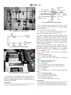
Figs. 1 and 2).
oil. D4175
6.3 Acid Solution Delivery System—An acid solution deliv-
3.1.4 reference oil, n—an oil of known performance
ery system that includes a multiple syringe pump with a ten
characteristics, used as a basis for comparison. D4175
position rack is required. The flow rate range minimum, using
3.1.4.1 Discussion—Reference oils are used to calibrate
a 0.5µL syringe, is 0.0001µL⁄h. The flow rate maximum,
testing facilities, to compare the performance of other oils, or
using a 140mLsyringe, is 220.82mL⁄min (see Figs. 3 and 4).
to evaluate other materials (such as seals) that interact with
6.4 Test Tube Assembly—The test tube assembly consists of
oils.
24 disposable plastic syringes and other common laboratory
3.1.5 rust (coatings), n—of iron or its alloys, a corrosion
apparatus.
product consisting of hydrated iron oxides, usually reddish in
color but can also be brown-to-black.
Special Technical Publication, “Multicylinder Test Sequences for Evaluating
Automotive Engine Oils,” Part, Sequence IIID ASTM STP 315H, Available from
ASTM Headquarters.
For referenced ASTM standards, visit the ASTM website, www.astm.org, or The sole source of supply of the apparatus known to the committee at this time
contact ASTM Customer Service at service@astm.org. For Annual Book of ASTM is Central Parts Distributor, Test Engineering Inc., 12718 Cimmaron Path, San
Standards volume information, refer to the standard’s Document Summary page on Antonio,TX 78249.
the ASTM website. If you are aware of alternative suppliers, please provide this information to
The last approved version of this historical standard is referenced on ASTMHeadquarters.Yourcommentswillreceivecarefulconsiderationatameeting
www.astm.org. of the responsible technical committee, which you may attend.
´1
D6557 − 18
FIG. 4 Schematic of Acid Delivery System
9,7
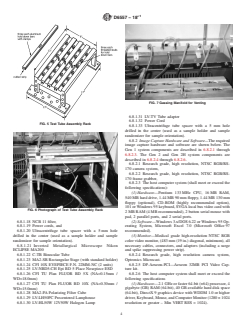
6.5.1 Aspecialtesttubeassemblyrack (seeFigs.5and6)
has 24 tube positions and is attached to the shaker platform
457mm by 457mm.
6.6 Air Delivery Manifold, required.
FIG. 1 Photograph of Air Delivery System
6.7 Venting System—Common laboratory apparatus is em-
ployed for the required venting system (see Fig. 7).
6.8 Image Analysis System—A specific imaging analysis
10,7
system is required. Three image analysis systems are
approved for use in this test: Generation 1 (Gen 1), Generation
2 (Gen 2), and a hybrid of these two systems Generation 2H
(Gen 2H). This hybrid system is composed of the equipment
described in 6.8.1.1 through 6.8.1.20, 6.8.2.4 through 6.8.2.6,
and 6.8.3.3 through 6.8.3.4.
6.8.1 Optics and Illumination—The required optics and
illumination equipment are shown below. The Gen 1 and Gen
FIG. 2 Schematic of Air Delivery System
2H system components are described in 6.8.1.1 through
6.8.1.20. The Gen 2 system components are described in
6.8.1.21 through 6.8.1.33.
6.8.1.1 Nikon Epiphot 200 inverted metallurgical
microscope,
6.8.1.2 BZ binocular head,
6.8.1.3 RV 3 plate mechanical stage,
6.8.1.4 CFWN 10× wide field eyepiece, high point
eyepiece,
6.8.1.5 Manual BD 5 place nosepiece,
6.8.1.6 Epiphot 300 EB block,
6.8.1.7 DF module,
6.8.1.8 CF BD plan 5×/0.13 plan achromat objective,
6.8.1.9 CF BD plan 10×/0.13 plan achromat objective,
6.8.1.10 EPI polarizer,
6.8.1.11 Analyzer,
6.8.1.12 Lamphouse for 12 V/100 W quartz halogen light
source,
FIG. 3 Photograph of Acid Delivery System
6.8.1.13 Lamphouse adapter,
6.8.1.14 12V⁄100W halogen bulbs,
6.8.1.15 300/200 100W power supply,
6.5 Temperature and Shaking Speed Control System—A
6.8.1.16 Remote control cable,
8,7
mechanical shaker, Bench-Top Environ Shaker Model 4628,
6.8.1.17 C-mount coupler for video camera,
provides an orbital shaking motion in a controlled speed and
temperature environment.
The sole source of supply of the apparatus known to the committee at this time
is West End Machine and Weld, Inc., P.O. Box 9444, Richmond, VA 23228.
8 10
The sole source of supply of the apparatus known to the committee at this time Thesolesourceofsupplyoftheapparatusknowntothecommitteeatthistime
th
is Labine, Inc., 15 and Bloomingdale, Melrose Park, IL 60160. is Meyer Instruments, Inc., 1304 Langham Creek, Suite 235, Houston, TX 77084.
´1
D6557 − 18
FIG. 7 Gassing Manifold for Venting
6.8.1.31 LV-TV Tube adapter
6.8.1.32 Power Cord
FIG. 5 Test Tube Assembly Rack
6.8.1.33 Ultracentrifuge tube spacer witha5mm hole
drilled in the center (used as a sample holder and sample
randomizer for sample orientation).
6.8.2 Image Capture Hardware and Software—Therequired
image capture hardware and software are shown below. The
Gen 1 system components are described in 6.8.2.1 through
6.8.2.3. The Gen 2 and Gen 2H system components are
described in 6.8.2.4 through 6.8.2.6.
6.8.2.1 Research grade, high resolution, NTSC RGB/RS-
170 camera system,
6.8.2.2 Research grade, high resolution, NTSC RGB/RS-
170 frame grabber,
6.8.2.3 The host computer system (shall meet or exceed the
following specifications):
(1) Hardware—Pentium 133MHz CPU, 16MB RAM,
540MB hard drive, 1.44MB 90mm floppy, 1.44MB 130mm
floppy (optional), CD-ROM (highly recommended option),
101orWindows95keyboard,SVGAlocalbusvideocardwith
FIG. 6 Photograph of Test Tube Assembly Rack
2MB RAM (4MB recommended), 2 button serial mouse with
pad, 2 parallel ports, and 2 serial ports.
6.8.1.18 NCB 11 filter, (2) Software—Windows3.x/DOS6.22orWindows95Op-
erating System, Microsoft Excel 7.0 (Microsoft Office97
6.8.1.19 Power cords, and
6.8.1.20 Ultracentrifuge tube spacer with a 5mm hole recommended).
drilled in the center (used as a sample holder and sample (3) Monitor—Medical grade high-resolution NTSC RGB
randomizer for sample orientation). colorvideomonitor,(483mm(19in.)diagonal,minimum),all
6.8.1.21 Inverted Metallurgical Microscope Nikon necessary cables, connectors, and adapters (including a surge
ECLIPSE MA200 and spike suppressing power strip).
6.8.1.22 C-TB Binocular Tube 6.8.2.4 Research grade, high resolution camera system,
6.8.1.23 MA2-SR Rectangular Stage (with standard holder) Optronics Microcast.
6.8.1.24 CFI 10X EYEPIECE F.N. 22MM-NC (2 units) 6.8.2.5 DP-Aexeon-PCI—Aexeon 32MB PCI Video Cap-
6.8.1.25 LV-NBD5-CH Epi BD 5 Place Nosepiece ESD ture kit.
6.8.1.26 CFI TU Plan FLUOR BD 5X (NA=0.15mm / 6.8.2.6 The host computer system shall meet or exceed the
WD=18.0mm) following specifications
6.8.1.27 CFI TU Plan FLUOR BD 10X (NA=0.30mm / (1) Hardware—2.1GHz or faster 64-bit (×64) processor, 4
WD=15.0mm) gigabyte (GB) RAM (64-bit), 40GB available hard disk space
6.8.1.28 MA2-PA Polarizing Filter Cube (64-bit), DirectX 9 graphics device withWDDM 1.0 or higher
6.8.1.29 LV-LH50PC Precentered Lamphouse driver,Keyboard,Mouse,andComputerMonitor(1280×1024
6.8.1.30 LV-HL50W 12V50W Halogen Lamp resolution or greater – Min VERT RES = 1024).
´1
D6557 − 18
(2) Software—Microsoft Windows 7 Pro (or Ultimate) – 8.2.1 Cut 24 separate pieces of TFE-fluorocarbon FEP
64-bit, Microsoft Excel 2010. tubing, each piece to be 240mm long.
(3) Secondary Monitor (for Camera)—Sony LMD- 8.2.1.1 Usecompressedair(fortechnicaluseonly),345kPa
2030MDW. minimum,toremovemostofthewater/oilemulsionthatcanbe
6.8.3 BRT Image Analysis Software—The required BRT trapped inside the short lengths of capillary tubing. Clean the
image analysis software for each system is shown below. The tubing with heptane (see 7.1.3), followed by acetone (see
Gen 1 system components are described in 6.8.3.1 through 7.1.2), and dry with compressed air.
6.8.3.2. The Gen 2 and Gen 2H system components are 8.2.2 Check the flangeless fitting for the TFE-fluorocarbon
described in 6.8.3.3 through 6.8.3.4.
tubing (O.D. 1.6mm) for deterioration, and replace as neces-
6.8.3.1 BRT macro program, and sary.
6.8.3.2 Optimate image analysis engine.
8.2.3 Remove and discard the plunger from a new 20mL
6.8.3.3 Meyer Instruments BRTGEN2.EXE, and disposable plastic syringe (Luer-Lok), and securely fasten the
6.8.3.4 Media Cybernetics IMAGE-PRO PLUS 7 image
syringe barrel to the short capillary tubing, using couplings,
1 1
analysis engine. ⁄4-28thread,andfemaleLuerCTFEfittings, ⁄4-28thread,and
with a 1.5mm bore.
7. Reagents and Materials
8.2.3.1 Label the syringes (test tubes) from 1 to 24.
7.1 Reagents:
8.2.4 Place the assembled test tube in the tube rack with the
7.1.1 Acid Solution (Warning——Corrosive. Combustible.
capillary tubing facing upward in the adjacent small hole.
Health hazard)—Obtain the acid solution from the CPD.
8.2.4.1 The test tube assembly rack is a specially designed
aluminum fabrication. It holds 24 test tubes with easy snap-on
NOTE 1—For information only. Appendix X1 contains details of the
lock, wing nuts, and hold-down bars (see Fig. 5).
acid solution.
8.2.5 Place one precleaned specimen into each test tube,
7.1.2 Acetone,99.5%.(Warning—Flammable.Healthhaz-
using forceps that are 180mm long, and have serrated tips to
ard.)
avoid contamination.
7.1.3 n-Heptane, 38% to 42% (purity), commercial grade,
8.2.6 Insert 10mL of test oil into each test tube, using a
with C isomers. (Warning—Flammable. Health hazard.)
disposable syringe with a capacity of 10mL.
7.2 Materials:
8.2.7 Secure the test tubes to the tube holder with three
7.2.1 TFE-fluorocarbon FEP Tubing, inside diameter (I.D.)
hold-down bars and three wing nuts.
0.8mm, outside diameter (O.D.) 1.6mm, 17 rolls, each roll
8.2.8 Fasten the test tube assembly rack to the shaker
11,7
305m. (Not required if the optional NRS flow controller is
platform with four custom-made wing bolts.
used.)
8.3 Acid Delivery System:
7.2.2 Vinyl Tubing, about 4.6m in length with an (I.D.)
8.3.1 Withdraw 6mL of acid solution by hand from a
3.2mm and an (O.D.) 6.4mm.
wide-mouth beaker into an individual disposable plastic sy-
7.2.3 Miscellaneous Common Laboratory Equipment, in-
ringe (Luer-Lok) with a capacity of 5mL.
cluding glassware, tubing fittings, trays, vials, and plastic
8.3.1.1 Attach the syringe to an acid inlet port of one of the
syringes.
24 three-way switching valves, with ⁄4-28 thread. (The other
8. Preparation of Apparatus
two ports are used for air inlet and mixed air/acid outlet.)
8.3.2 Turn the three-way valve to two-way open and eject,
8.1 Specimens:
by hand, about 0.5 mL of acid solution into a waste beaker,
8.1.1 Remove the appropriate number of specimens from
while ensuring that no air bubbles remain in the syringe.
vacuum-sealed packages into a 118mL bottle (clear, medium-
8.3.2.1 Place the syringe that now contains about 5.5mLof
round with cap). Add sufficient heptane (see 7.1.3), approxi-
acid solution on the holder of the multiple syringes pump.
mately 59mL, to cover specimens.
8.1.2 Cap the bottle loosely and place it in an ultrasonic 8.3.3 Repeat the above procedure for the other 23 acid
delivery syringes.
cleaning bath. Sonicate for 30min, and then decant the
heptane. 8.3.4 There are three multiple syringe pumps, and eight of
the 5mL syringes are attached to each of the pumps.
8.1.3 Rinsetwomoretimeswithheptaneandfollowwithan
acetone (see 7.1.2) rinse to ensure the specimens are free of 8.3.4.1 The pumps each have a ten-position rack and are
contamination. Dry the specimens with nitrogen for 30s to required to satisfy a minimum flow rate range of 0.0001µL⁄h
60s. to 220.82mL⁄min. Required accuracy is 61%, and reproduc-
ibility is 60.1%.
NOTE 2—The specimens can be prepared up to one week in advance
8.3.5 Ensure that the syringe barrel flange and the plunger
and stored in heptane until needed for testing.
flange are firmly held by the six retaining clamps, which are
8.2 Test Tube Assembly, Tube Rack, and Shaker for Each
51mmC-clampsthatsecuretheendsofthehold-downbarsof
Test Tube:
the multiple syringes pump.
8.3.5.1 Good alignment of all 24 acid delivery syringes
Brooks Model 8744 NRS Flow Controller has been determined to be
against the retaining brackets is crucial to ensure repeatability.
acceptable for this application.The sole source of supply of the apparatus known to
(See Fig. 3 for a photograph of the acid delivery system, and
the committee at this time is McPac ProcessAutomation and Control, 8040 Bavaria
Rd., Twinsburg, OH 44087. Fig. 4 for a schematic.)
´1
D6557 − 18
8.3.6 Cut 24 pieces of TFE-fluorocarbon tubing; each piece 9.3 Set the actual air flow rate to 40mL⁄min.
to be 1295mm 6 25.4mm in length. 9.3.1 Monitortheairflowratewiththecalibratedflowmeter
8.3.6.1 Attach each of these tubes to the mixed air/acid connected to the reference air capillary tubing. Refer to the
outlet ports of the three-way switching valves. calibration chart developed in Annex A1 to determine the
actual air flow rate setting.
8.4 Air Delivery System:
8.4.1 Clean, dry air, compressed to at least 345kPa, is 9.4 Turn the three-way valves to the three-way open
required. position, and dry the nominal 1295mm lengths of capillary
8.4.2 A single stage, high-purity stainless steel pressure tubing with air for 30min.
regulatoristhefirstintheline;thisisequippedwitha0kPato
9.5 Measure and record the airflow rates of all lines, and
1100kPa maximum pressure gauge.
then shut off the main airflow valve.
8.4.3 Two compressed air filters capable of removing par-
9.6 Connect the long capillary tubing (that is, the nominal
ticles and mists are required, and are next in the line.
lengths of 1295mm) to the short capillary tubing from the test
8.4.3.1 The first filter in the line is an A912-DX type,
tubes.
followed by an A912-BX type. These have polycarbonate
9.7 Connect all 24 stopper vent lines to the top of the test
bowls and should be equipped with aluminum shields. They
have ⁄4in.NPT(F)portsandwillwithstand1034kPapressure tubes.
9.7.1 TFE-fluorocarbon thermometer adapters are used as
maximum.
stoppers, ⁄22 joint.
NOTE3—Alternatively,zerogradeaircylinderscanbeusedandwillnot
9.7.2 Attach the vent lines to barbed tee connectors (clear
require the extensive filtering outlined above.
polypropylene tubing, with an I.D. of 3.2mm).
8.4.4 A Drierite gas purifier, with a maximum working
9.7.3 Then, connect the vent outlets to a gas venting
pressure of 690kPa, is next in the line.
manifold (8 port inlet with hose barbs, size 6.4mm; use vinyl
8.4.4.1 The first portion of the purifier (about 75%) con-
tubing with an I.D. of 3.2mm by an O.D. of 6.4mm (see Fig.
tains a molecular sieve, activated, Type 4A, 8 to 12 mesh.
7).
8.4.4.2 The remaining portion of the purifier (about 25%)
9.7.4 Finally, connect the gas venting manifold’s outlet to a
contains Drierite absorbent, color indicating type, 8 mesh.
condensate trap flask (with a side arm) having a capacity of
8.4.5 Next in the line is the downstream regulator, single
1000mL, placed such that gravity drains the condensate from
stage high-purity stainless steel, that is equipped with a 0kPa
the test tubes. Make sure that all of the capillary tubes are free
to 415kPa pressure gauge.
to move with the shaker platform.
8.4.6 The next installation is a relief valve, in-line adjust-
9.8 Set the shaker temperature to maintain 48°C 6 0.1°C,
able CA series, 345kPa to 1035kPa cracking pressure range,
as measured in an actual oil sample, and warm up the entire
set at 550kPa (optional to control over pressure).
systemtothecontroltemperatureintheoilsampleforaperiod
8.4.7 Lastly, install an air delivery manifold with 25 port
of 1h. Refer to the calibration chart developed inAnnexA2 to
outlets and 6.4mm tube fittings. (See Figs. 1 and 2 for a
determine the shaker temperature setting.
photograph and schematic of the air system.)
8.4.8 Cut 25 pieces of the TFE-fluorocarbon tubing, each
9.9 Following the 1h warm-up period, turn on the shaker,
piece to be approximately 183m in length. set the shaker speed to 300r⁄min, and ensure that each ball
8.4.8.1 Theselongtubesprovidethenecessarybackpressure
freely rotates against each syringe wall.
to allow good control of the very low airflow rate. The
9.10 Startintroducingtheacidsolutionatanactualflowrate
individual lengths may need to be adjusted slightly to ensure
of 0.193mL⁄h. Refer to the calibration chart developed in
the same flow rates at a given delivery pressure.An equivalent
Annex A3 to determine the actual flow rate setting.
11,7
multiport flow control system can be used.
9.11 Turn on the main airflow valve; check and adjust, if
8.4.8.2 Connect these tubes to the air delivery manifold.
necessary, the upstream pressure (that is, upstream from the
(1)Connect one of these tubes to a calibrated flowmeter,
three-way valves) to ensure that the actual air flow rate is
capable of measuring up to 200mL⁄min, and with a resolution
40mL⁄min.
of 0.1mL⁄min (see Annex A1).
(2)Connect the other 24 tubes to the air inlet ports on the
9.12 Maintain the above test conditions for 18h.
24 three-way valves.
9.13 At the end of the test, stop the syringe pumps, shut off
the airflow, and turn off the shaker.
9. Procedure
9.14 Disconnect the acid/air delivery tubes from the test
9.1 Turn the three-way valve to two-way open, activate the
tube assembly, and remove the stoppers from the test tubes.
syringe pumps, and eject 1mL of acid solution into a waste
NOTE 4—The preceding procedure described the use of three multiple
beaker at a speed of 0.1mL⁄min.
syringe pumps and 24 test tubes. However, as a minimum, one multiple
9.1.1 Makesurethattheretainingbracketsproperlyalignall
syringe pump with a maximum of 10 test tubes can also be utilized.
24 syringe plungers.
10. Reference Oil Testing
9.2 Adjust the acid solution flow rate to 0.193mL⁄h (test
flowrate),andrunfor1htoensurethatallsyringeplungersare 10.1 AnnexA5andAnnexA6describetheroleoftheTMC
properly aligned at the retaining brackets of the pusher block. in reference oil testing.
´1
D6557 − 18
10.2 Procure a supply of reference oils directly from the 11.1.3 Put the vial holder into a utility tray (stainless steel,
TMC. 310mm by 200mm by 60mm), pour enough heptane into the
tray to cover the specimens, and shake the tray gently for 30s
10.2.1 Provide theTMC with the shaker table identification
to 60s before decanting the heptane.
for the test.
11.1.4 Put enough heptane (see 7.1.3) into the tray to cover
10.2.2 Test the assigned reference oil along with each batch
the specimens, and
...