


ASTM G108-94(2015)
(Test Method)Standard Test Method for Electrochemical Reactivation (EPR) for Detecting Sensitization of AISI Type 304 and 304L Stainless Steels
Standard Test Method for Electrochemical Reactivation (EPR) for Detecting Sensitization of AISI Type 304 and 304L Stainless Steels
SIGNIFICANCE AND USE
5.1 This test method describes an EPR test method for quantitatively determining the relative degree of sensitization in AISI Type 304 and 304L stainless steels. The EPR test has found wide use as a means to provide a numerical level of sensitization in studies of the effects of sensitization on intergranular corrosion and intergranular stress corrosion cracking behavior. The results of this test method correlate with other test methods (for example, Practices A262 and Test Methods G28) that are commonly used to assess sensitization in stainless steels.
5.2 The EPR test can also be used for product acceptance, service evaluation, regulatory statutes, and manufacturing controls providing that both the supplier and user have agreed upon appropriate acceptance criteria and a sensitizing treatment. The test is not intended for design purposes since the test conditions accelerate corrosion in a manner that does not simulate any actual service environment.
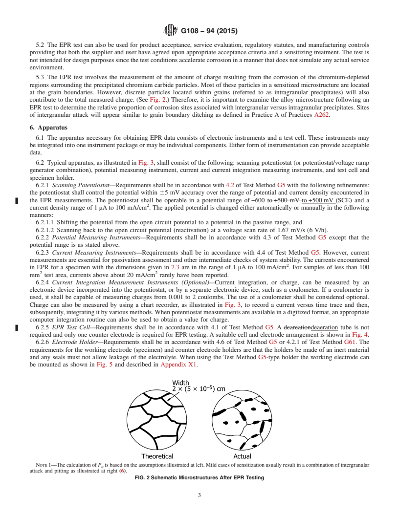
5.3 The EPR test involves the measurement of the amount of charge resulting from the corrosion of the chromium-depleted regions surrounding the precipitated chromium carbide particles. Most of these particles in a sensitized microstructure are located at the grain boundaries. However, discrete particles located within grains (referred to as intragranular precipitates) will also contribute to the total measured charge. (See Fig. 2.) Therefore, it is important to examine the alloy microstructure following an EPR test to determine the relative proportion of corrosion sites associated with intergranular versus intragranular precipitates. Sites of intergranular attack will appear similar to grain boundary ditching as defined in Practice A of Practices A262.
Note 1: The calculation of Pa is based on the assumptions illustrated at left. Mild cases of sensitization usually result in a combination of intergranular attack and pitting as illustrated at right (6).
SCOPE
1.1 This test method covers a laboratory procedure for conducting an electrochemical reactivation (EPR) test on AISI Type 304 and 304L (UNS No. S30400 and S30403, respectively) stainless steels. This test method can provide a nondestructive means of quantifying the degree of sensitization in these steels (1, 2, 3).2 This test method has found wide acceptance in studies of the effects of sensitization on intergranular corrosion and intergranular stress corrosion cracking behavior (see Terminology G15). The EPR technique has been successfully used to evaluate other stainless steels and nickel base alloys (4), but the test conditions and evaluation criteria used were modified in each case from those cited in this test method.
1.2 The values stated in SI units are to be regarded as the standard. The inch-pound units given in parentheses are for information only.
1.3 This standard does not purport to address all of the safety concerns, if any, associated with its use. It is the responsibility of the user of this standard to establish appropriate safety and health practices and determine the applicability of regulatory limitations prior to use.
General Information
Buy Standard
Standards Content (Sample)
NOTICE: This standard has either been superseded and replaced by a new version or withdrawn.
Contact ASTM International (www.astm.org) for the latest information
Designation: G108 − 94 (Reapproved 2015)
Standard Test Method for
Electrochemical Reactivation (EPR) for Detecting
Sensitization of AISI Type 304 and 304L Stainless Steels
This standard is issued under the fixed designation G108; the number immediately following the designation indicates the year of
original adoption or, in the case of revision, the year of last revision. A number in parentheses indicates the year of last reapproval. A
superscript epsilon (´) indicates an editorial change since the last revision or reapproval.
1. Scope E112 Test Methods for Determining Average Grain Size
G1 Practice for Preparing, Cleaning, and Evaluating Corro-
1.1 This test method covers a laboratory procedure for
sion Test Specimens
conducting an electrochemical reactivation (EPR) test on AISI
G3 Practice for Conventions Applicable to Electrochemical
Type 304 and 304L (UNS No. S30400 and S30403, respec-
Measurements in Corrosion Testing
tively) stainless steels. This test method can provide a nonde-
G5 Reference Test Method for Making Potentiodynamic
structive means of quantifying the degree of sensitization in
2 Anodic Polarization Measurements
these steels (1, 2, 3). This test method has found wide
G15 Terminology Relating to Corrosion and Corrosion Test-
acceptance in studies of the effects of sensitization on inter-
ing (Withdrawn 2010)
granular corrosion and intergranular stress corrosion cracking
G28 Test Methods for Detecting Susceptibility to Inter-
behavior (see Terminology G15). The EPR technique has been
granular Corrosion in Wrought, Nickel-Rich, Chromium-
successfully used to evaluate other stainless steels and nickel
Bearing Alloys
base alloys (4), but the test conditions and evaluation criteria
G61 Test Method for Conducting Cyclic Potentiodynamic
used were modified in each case from those cited in this test
Polarization Measurements for Localized Corrosion Sus-
method.
ceptibility of Iron-, Nickel-, or Cobalt-Based Alloys
1.2 The values stated in SI units are to be regarded as the
standard. The inch-pound units given in parentheses are for
3. Terminology
information only.
3.1 Definitions of Terms Specific to This Standard:
1.3 This standard does not purport to address all of the
3.1.1 integrated charge (Q)—the charge measured, in
safety concerns, if any, associated with its use. It is the
coulombs, during reactivation as given by the time integral of
responsibility of the user of this standard to establish appro-
current density below the reactivation peak of the curve.
priate safety and health practices and determine the applica-
3.1.2 maximum anodic current density (I )—the current
r
bility of regulatory limitations prior to use.
density measured at the peak of the anodic curve during
reactivation.
2. Referenced Documents
3.1.3 normalized charge (P )—the integrated current nor-
3 a
2.1 ASTM Standards:
malized to the specimen size and grain size. P represents the
a
A262 Practices for Detecting Susceptibility to Intergranular
charge (in coulombs/cm ) of the grain-boundary area. The
Attack in Austenitic Stainless Steels
method for calculating P is given in 9.2.
a
D1193 Specification for Reagent Water
3.1.4 reactivation—in the electrochemical reactivation
E3 Guide for Preparation of Metallographic Specimens
(EPR) test, the potential sweep from the passivation potential
E7 Terminology Relating to Metallography
returning to the corrosion potential.
3.1.5 scan rate—the rate at which the electrical potential
applied to a specimen in a polarization test is changed.
This test method is under the jurisdiction of ASTM Committee G01 on
Corrosion of Metals and is the direct responsibility of Subcommittee G01.11 on
Electrochemical Measurements in Corrosion Testing.
4. Summary of Test Method
Current edition approved Nov. 1, 2015. Published December 2015. Originally
4.1 The EPR test is accomplished by a potentiodynamic
approved in 1992. Last previous edition approved in 2010 as G108–94(2010). DOI:
10.1520/G0108-94R15.
sweep from the passive to the active regions of electrochemical
The boldface numbers in parentheses refer to a list of references at the end of
potentials in a process referred to as reactivation. The EPR test
this standard.
For referenced ASTM standards, visit the ASTM website, www.astm.org, or
contact ASTM Customer Service at service@astm.org. For Annual Book of ASTM
Standards volume information, refer to the standard’s Document Summary page on The last approved version of this historical standard is referenced on
the ASTM website. www.astm.org.
Copyright © ASTM International, 100 Barr Harbor Drive, PO Box C700, West Conshohocken, PA 19428-2959. United States
G108 − 94 (2015)
measures the amount of charge associated with the corrosion of activated and show higher Q and I values than solution
r
the chromium-depleted regions surrounding chromium carbide annealed steels, that are not susceptible to intergranular corro-
precipitated particles. Most of these particles in a sensitized sion. The value Q is normalized for both specimen size and
microstructure are located at grain boundaries (see Terminol- grain size. The value normalized in this fashion is called P and
a
ogy E7). Discrete particles located within the grain (referred to represents the charge (in units of coulombs) per unit grain-
as intragranular precipitates) will also contribute to the total boundary area. This normalization permits direct comparisons
measured charge. Therefore, it is important to examine the of different heats of material that exhibit different Q values
alloy microstructure following an EPR test, to determine the solely as a result of differences in grain size.
relative proportion of corrosion site associated with intergranu-
lar versus intragranular precipitates. 5. Significance and Use
4.2 The chromium-depleted zones around carbide precipi- 5.1 This test method describes an EPR test method for
tates in sensitized steels are particularly susceptible to corro- quantitatively determining the relative degree of sensitization
sion in oxidizing acid solutions. Corrosion at chromium- in AISI Type 304 and 304L stainless steels. The EPR test has
depleted grain boundary sites causes a rapid rise in the current found wide use as a means to provide a numerical level of
density when the electrochemical potential is changed from the
sensitization in studies of the effects of sensitization on
passive to the active region. intergranular corrosion and intergranular stress corrosion
cracking behavior. The results of this test method correlate
4.3 A sensitized steel produces a curve similar to the active
with other test methods (for example, Practices A262 and Test
portion of the polarization curve during the reactivation from
Methods G28) that are commonly used to assess sensitization
the passive region back to the rest potential (E ) as shown in
corr
in stainless steels.
Fig. 1. A nonsensitized (solution annealed) steel polarized
under the conditions given in this test method will produce a
5.2 The EPR test can also be used for product acceptance,
curve with lower current densities than a sensitized steel. service evaluation, regulatory statutes, and manufacturing
controls providing that both the supplier and user have agreed
4.4 The EPR test results are readily reproducible, as long as
upon appropriate acceptance criteria and a sensitizing treat-
the electrolyte temperature, electrolyte composition, and scan
ment. The test is not intended for design purposes since the test
rate are carefully controlled. The EPR test is significantly
conditions accelerate corrosion in a manner that does not
affected by the composition, thermomechanical condition and
simulate any actual service environment.
surface finish of the specimen as well as the presence of
non-metallic inclusions, that result in pitting of the etched 5.3 The EPR test involves the measurement of the amount
microstructure. of charge resulting from the corrosion of the chromium-
depleted regions surrounding the precipitated chromium car-
NOTE 1—Various cutting and grinding operations can promote sensiti-
bide particles. Most of these particles in a sensitized micro-
zation of Type 304 (5). Superficial carbide precipitation can occur during
structure are located at the grain boundaries. However, discrete
cutting and grinding or during subsequent low temperature heat
treatments, such as 24 h at 500°C.
particles located within grains (referred to as intragranular
precipitates) will also contribute to the total measured charge.
4.5 The criteria used to distinguish between sensitized and
(See Fig. 2.) Therefore, it is important to examine the alloy
solution annealed samples are the activation charge density, Q
microstructure following an EPR test to determine the relative
(given by the time integral of current density below the
proportion of corrosion sites associated with intergranular
reactivation peak of the curve), or the maximum anodic current
versus intragranular precipitates. Sites of intergranular attack
density, I , in the active state. Sensitized steels are easily
r
will appear similar to grain boundary ditching as defined in
Practice A of Practices A262.
NOTE 1—The calculation of P is based on the assumptions illustrated
a
at left. Mild cases of sensitization usually result in a combination of
intergranular attack and pitting as illustrated at right (6).
FIG. 1 Schematic EPR Curves for Sensitized and Solutionized
AISI Type 304 Stainless Steel FIG. 2 Schematic Microstructures After EPR Testing
G108 − 94 (2015)
6. Apparatus eter is used, it shall be capable of measuring charges from
0.001 to 2 coulombs. The use of a coulometer shall be
6.1 The apparatus necessary for obtaining EPR data consists
considered optional. Charge can also be measured by using a
of electronic instruments and a test cell. These instruments may
chart recorder, as illustrated in Fig. 3, to record a current versus
be integrated into one instrument package or may be individual
time trace and then, subsequently, integrating it by various
components. Either form of instrumentation can provide ac-
methods. When potentiostat measurements are available in a
ceptable data.
digitized format, an appropriate computer integration routine
6.2 Typical apparatus, as illustrated in Fig. 3, shall consist of
can also be used to obtain a value for charge.
the following: scanning potentiostat (or potentiostat/voltage
6.2.5 EPR Test Cell—Requirements shall be in accordance
ramp generator combination), potential measuring instrument,
with 4.1 of Test Method G5. A deaeration tube is not required
current and current integration measuring instruments, and test
and only one counter electrode is required for EPR testing. A
cell and specimen holder.
suitable cell and electrode arrangement is shown in Fig. 4.
6.2.1 Scanning Potentiostat—Requirements shall be in ac-
6.2.6 Electrode Holder—Requirements shall be in accor-
cordance with 4.2 of Test Method G5 with the following
dance with 4.6 of Test Method G5 or 4.2.1 of Test Method G61.
refinements: the potentiostat shall control the potential within
The requirements for the working electrode (specimen) and
65 mV accuracy over the range of potential and current
counter electrode holders are that the holders be made of an
density encountered in the EPR measurements. The poten-
inert material and any seals must not allow leakage of the
tiostat shall be operable in a potential range of −600
electrolyte. When using the Test Method G5-type holder the
to +500 mV (SCE) and a current density range of 1 µA to 100
working electrode can be mounted as shown in Fig. 5 and
mA/cm . The applied potential is changed either automatically
described in Appendix X1.
or manually in the following manners:
6.2.7 Auxiliary (Counter) Electrodes—Requirements are in
6.2.1.1 Shifting the potential from the open circuit potential
accordance with 4.7.2 of Test Method G5 except that only one
to a potential in the passive range, and
counter electrode is necessary for EPR testing. However, two
6.2.1.2 Scanning back to the open circuit potential (reacti-
auxiliary electrodes can provide for a more uniform distribu-
vation) at a voltage scan rate of 1.67 mV/s (6 V/h).
tion of current. Titanium or high-purity carbon may be used in
6.2.2 Potential Measuring Instruments—Requirements shall
place of platinum for the counter electrode since it is always
be in accordance with 4.3 of Test Method G5 except that the
the cathode.
potential range is as stated above.
6.2.8 Calomel Reference Electrode—Requirements are in
6.2.3 Current Measuring Instruments—Requirements shall
accordance or equivalent to 4.7.3 of Test Method G5.
be in accordance with 4.4 of Test Method G5. However, current
measurements are essential for passivation assessment and
7. Sampling, Test Specimens, and Test Units
other intermediate checks of system stability. The currents
7.1 Sampling:
encountered in EPR for a specimen with the dimensions given
7.1.1 When using this test method to meet product accep-
in 7.3 are in the range of 1 µA to 100 mA/cm . For samples of
tance criteria, the means of sampling of a test specimen shall be
2 2
less than 100 mm test area, currents above about 20 mA/cm
rarely have been reported.
6.2.4 Current Integration Measurement Instruments
(Optional)—Current integration, or charge, can be measured by
an electronic device incorporated into the potentiostat, or by a
separate electronic device, such as a coulometer. If a coulom-
NOTE 1—The sample face is completely immersed but the connection to
the electrode holder is not immersed.
FIG. 4 Schematic Diagram of an Electrochemical Cell for EPR
FIG. 3 Schematic Diagram of an EPR Test Apparatus Testing
G108 − 94 (2015)
7.3.2 Remove any oxides or grease from the specimen as
such film may promote loss of adhesion between the mounting
compound and the specimen that could cause a crevice to form
thereby producing erroneously high current densities during
the EPR measurement.
7.3.3 The front surface of the specimen will be evaluated in
the EPR test. The back surface of the test specimen is used to
establish electrical contact with the specimen (see Note 2).
NOTE 2—A convenient way to make this attachment may be either by
spot welding or by using a conducting cement to fasten a stainless steel
machine screw (for example, NC4-40 × 0.3 cm (0.75 in.) long) to the back
surface of the specimen. This assembly is mounted in a suitable compound
that is inert in the EPR electrolyte (see Appendix X1) such that the front
surface upon immersion in the EPR electrolyte is fully in contact with the
electrolyte.
7.3.4 Measure the surface area of the front surface of the tes
...
This document is not an ASTM standard and is intended only to provide the user of an ASTM standard an indication of what changes have been made to the previous version. Because
it may not be technically possible to adequately depict all changes accurately, ASTM recommends that users consult prior editions as appropriate. In all cases only the current version
of the standard as published by ASTM is to be considered the official document.
Designation: G108 − 94 (Reapproved 2010) G108 − 94 (Reapproved 2015)
Standard Test Method for
Electrochemical Reactivation (EPR) for Detecting
Sensitization of AISI Type 304 and 304L Stainless Steels
This standard is issued under the fixed designation G108; the number immediately following the designation indicates the year of
original adoption or, in the case of revision, the year of last revision. A number in parentheses indicates the year of last reapproval. A
superscript epsilon (´) indicates an editorial change since the last revision or reapproval.
1. Scope
1.1 This test method covers a laboratory procedure for conducting an electrochemical reactivation (EPR) test on AISI Type 304
and 304L (UNS No. S30400 and S30403, respectively) stainless steels. This test method can provide a nondestructive means of
quantifying the degree of sensitization in these steels (1, 2, 3). This test method has found wide acceptance in studies of the effects
of sensitization on intergranular corrosion and intergranular stress corrosion cracking behavior (see Terminology G15). The EPR
technique has been successfully used to evaluate other stainless steels and nickel base alloys (4), but the test conditions and
evaluation criteria used were modified in each case from those cited in this test method.
1.2 The values stated in SI units are to be regarded as the standard. The inch-pound units given in parentheses are for
information only.
1.3 This standard does not purport to address all of the safety concerns, if any, associated with its use. It is the responsibility
of the user of this standard to establish appropriate safety and health practices and determine the applicability of regulatory
limitations prior to use.
2. Referenced Documents
2.1 ASTM Standards:
A262 Practices for Detecting Susceptibility to Intergranular Attack in Austenitic Stainless Steels
D1193 Specification for Reagent Water
E3 Guide for Preparation of Metallographic Specimens
E7 Terminology Relating to Metallography
E112 Test Methods for Determining Average Grain Size
G1 Practice for Preparing, Cleaning, and Evaluating Corrosion Test Specimens
G3 Practice for Conventions Applicable to Electrochemical Measurements in Corrosion Testing
G5 Reference Test Method for Making Potentiodynamic Anodic Polarization Measurements
G15 Terminology Relating to Corrosion and Corrosion Testing (Withdrawn 2010)
G28 Test Methods for Detecting Susceptibility to Intergranular Corrosion in Wrought, Nickel-Rich, Chromium-Bearing Alloys
G61 Test Method for Conducting Cyclic Potentiodynamic Polarization Measurements for Localized Corrosion Susceptibility of
Iron-, Nickel-, or Cobalt-Based Alloys
3. Terminology
3.1 Definitions of Terms Specific to This Standard:
3.1.1 integrated charge (Q)—the charge measured, in couloumbs,coulombs, during reactivation as given by the time integral of
current density below the reactivation peak of the curve.
3.1.2 maximum anodic current density (I )—the current density measured at the peak of the anodic curve during reactivation.
r
This test method is under the jurisdiction of ASTM Committee G01 on Corrosion of Metals and is the direct responsibility of Subcommittee G01.11 on Electrochemical
Measurements in Corrosion Testing.
Current edition approved May 1, 2010Nov. 1, 2015. Published May 2010December 2015. Originally approved in 1992. Last previous edition approved in 20042010 as
ε1
G108–94(2004)G108–94(2010). . DOI: 10.1520/G0108-94R10.10.1520/G0108-94R15.
The boldface numbers in parentheses refer to a list of references at the end of this standard.
For referenced ASTM standards, visit the ASTM website, www.astm.org, or contact ASTM Customer Service at service@astm.org. For Annual Book of ASTM Standards
volume information, refer to the standard’s Document Summary page on the ASTM website.
The last approved version of this historical standard is referenced on www.astm.org.
Copyright © ASTM International, 100 Barr Harbor Drive, PO Box C700, West Conshohocken, PA 19428-2959. United States
G108 − 94 (2015)
3.1.3 normalized charge (P )—the integrated current normalized to the specimen size and grain size. P represents the charge
a a
(in coulombs/cm ) of the grain-boundary area. The method for calculating P is given in 9.2.
a
3.1.4 reactivation—in the electrochemical reactivation (EPR) test, the potential sweep from the passivation potential returning
to the corrosion potential.
3.1.5 scan rate—the rate at which the electrical potential applied to a specimen in a polarization test is changed.
4. Summary of Test Method
4.1 The EPR test is accomplished by a potentiodynamic sweep from the passive to the active regions of electrochemical
potentials in a process referred to as reactivation. The EPR test measures the amount of charge associated with the corrosion of
the chromium-depleted regions surrounding chromium carbide precipitated particles. Most of these particles in a sensitized
microstructure are located at grain boundaries (see Terminology E7). Discrete particles located within the grain (referred to as
intragranular precipitates) will also contribute to the total measured charge. Therefore, it is important to examine the alloy
microstructure following an EPR test, to determine the relative proportion of corrosion site associated with intergranular versus
intragranular precipitates.
4.2 The chromium-depleted zones around carbide precipitates in sensitized steels are particularly susceptible to corrosion in
oxidizing acid solutions. Corrosion at chromium-depleted grain boundary sites causes a rapid rise in the current density when the
electrochemical potential is changed from the passive to the active region.
4.3 A sensitized steel produces a curve similar to the active portion of the polarization curve during the reactivation from the
passive region back to the rest potential (E ) as shown in Fig. 1. A nonsensitized (solution annealed) steel polarized under the
corr
conditions given in this test method will produce a curve with lower current densities than a sensitized steel.
4.4 The EPR test results are readily reproducible, as long as the electrolyte temperature, electrolyte composition, and scan rate
are carefully controlled. The EPR test is significantly affected by the composition, thermomechanical condition and surface finish
of the specimen as well as the presence of non-metallic inclusions, that result in pitting of the etched microstructure.
NOTE 1—Various cutting and grinding operations can promote sensitization of Type 304 (5). Superficial carbide precipitation can occur during cutting
and grinding or during subsequent low temperature heat treatments, such as 24 h at 500°C.
4.5 The criteria used to distinguish between sensitized and solution annealed samples are the activation charge density, Q (given
by the time integral of current density below the reactivation peak of the curve), or the maximum anodic current density, I , in the
r
active state. Sensitized steels are easily activated and show higher Q and I values than solution annealed steels, that are not
r
susceptible to intergranular corrosion. The value Q is normalized for both specimen size and grain size. The value normalized in
this fashion is called P and represents the charge (in units of coulombs) per unit grain-boundary area. This normalization permits
a
direct comparisons of different heats of material that exhibit different Q values solely as a result of differences in grain size.
5. Significance and Use
5.1 This test method describes an EPR test method for quantitatively determining the relative degree of sensitization in AISI
Type 304 and 304L stainless steels. The EPR test has found wide use as a means to provide a numerical level of sensitization in
studies of the effects of sensitization on intergranular corrosion and intergranular stress corrosion cracking behavior. The results
of this test method correlate with other test methods (for example, Practices A262 and Test Methods G28) that are commonly used
to assess sensitization in stainless steels.
FIG. 1 Schematic EPR Curves for Sensitized and Solutionized AISI Type 304 Stainless Steel
G108 − 94 (2015)
5.2 The EPR test can also be used for product acceptance, service evaluation, regulatory statutes, and manufacturing controls
providing that both the supplier and user have agreed upon appropriate acceptance criteria and a sensitizing treatment. The test is
not intended for design purposes since the test conditions accelerate corrosion in a manner that does not simulate any actual service
environment.
5.3 The EPR test involves the measurement of the amount of charge resulting from the corrosion of the chromium-depleted
regions surrounding the precipitated chromium carbide particles. Most of these particles in a sensitized microstructure are located
at the grain boundaries. However, discrete particles located within grains (referred to as intragranular precipitates) will also
contribute to the total measured charge. (See Fig. 2.) Therefore, it is important to examine the alloy microstructure following an
EPR test to determine the relative proportion of corrosion sites associated with intergranular versus intragranular precipitates. Sites
of intergranular attack will appear similar to grain boundary ditching as defined in Practice A of Practices A262.
6. Apparatus
6.1 The apparatus necessary for obtaining EPR data consists of electronic instruments and a test cell. These instruments may
be integrated into one instrument package or may be individual components. Either form of instrumentation can provide acceptable
data.
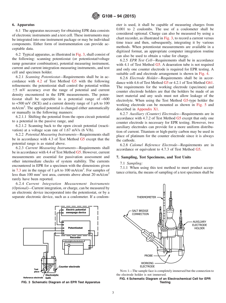
6.2 Typical apparatus, as illustrated in Fig. 3, shall consist of the following: scanning potentiostat (or potentiostat/voltage ramp
generator combination), potential measuring instrument, current and current integration measuring instruments, and test cell and
specimen holder.
6.2.1 Scanning Potentiostat—Requirements shall be in accordance with 4.2 of Test Method G5 with the following refinements:
the potentiostat shall control the potential within 65 mV accuracy over the range of potential and current density encountered in
the EPR measurements. The potentiostat shall be operable in a potential range of −600 to +500 mV to +500 mV (SCE) and a
current density range of 1 μA to 100 mA/cm . The applied potential is changed either automatically or manually in the following
manners:
6.2.1.1 Shifting the potential from the open circuit potential to a potential in the passive range, and
6.2.1.2 Scanning back to the open circuit potential (reactivation) at a voltage scan rate of 1.67 mV/s (6 V/h).
6.2.2 Potential Measuring Instruments—Requirements shall be in accordance with 4.3 of Test Method G5 except that the
potential range is as stated above.
6.2.3 Current Measuring Instruments—Requirements shall be in accordance with 4.4 of Test Method G5. However, current
measurements are essential for passivation assessment and other intermediate checks of system stability. The currents encountered
in EPR for a specimen with the dimensions given in 7.3 are in the range of 1 μA to 100 mA/cm . For samples of less than 100
2 2
mm test area, currents above about 20 mA/cm rarely have been reported.
6.2.4 Current Integration Measurement Instruments (Optional)—Current integration, or charge, can be measured by an
electronic device incorporated into the potentiostat, or by a separate electronic device, such as a coulometer. If a coulometer is
used, it shall be capable of measuring charges from 0.001 to 2 coulombs. The use of a coulometer shall be considered optional.
Charge can also be measured by using a chart recorder, as illustrated in Fig. 3, to record a current versus time trace and then,
subsequently, integrating it by various methods. When potentiostat measurements are available in a digitized format, an appropriate
computer integration routine can also be used to obtain a value for charge.
6.2.5 EPR Test Cell—Requirements shall be in accordance with 4.1 of Test Method G5. A deareationdeaeration tube is not
required and only one counter electrode is required for EPR testing. A suitable cell and electrode arrangement is shown in Fig. 4.
6.2.6 Electrode Holder—Requirements shall be in accordance with 4.6 of Test Method G5 or 4.2.1 of Test Method G61. The
requirements for the working electrode (specimen) and counter electrode holders are that the holders be made of an inert material
and any seals must not allow leakage of the electrolyte. When using the Test Method G5-type holder the working electrode can
be mounted as shown in Fig. 5 and described in Appendix X1.
NOTE 1—The calculation of P is based on the assumptions illustrated at left. Mild cases of sensitization usually result in a combination of intergranular
a
attack and pitting as illustrated at right (6).
FIG. 2 Schematic Microstructures After EPR Testing
G108 − 94 (2015)
FIG. 3 Schematic Diagram of an EPR Test Apparatus
NOTE 1—The sample face is completely immersed but the connection to the electrode holder is not immersed.
FIG. 4 Schematic Diagram of an Electrochemical Cell for EPR Testing
6.2.7 Auxiliary (Counter) Electrodes—Requirements are in accordance with 4.7.2 of Test Method G5 except that only one
counter electrode is necessary for EPR testing. However, two auxiliary electrodes can provide for a more uniform distribution of
current. Titanium or high-purity carbon may be used in place of platinum for the counter electrode since it is always the cathode.
6.2.8 Calomel Reference Electrode—Requirements are in accordance or equivalent to 4.7.3 of Test Method G5.
7. Sampling, Test Specimens, and Test Units
7.1 Sampling:
7.1.1 When using this test method to meet product acceptance criteria, the means of sampling of a test specimen shall be decided
by agreement between the parties involved; for instance, but not limited to, a user and a supplier.
7.1.2 Specimens removed form a piece of AISI Type 304 or 304L steel by shearing, cutting, burning, and so forth shall have
the affected edges removed by grinding or machining.
7.2 Sensitization of Test Specimens—Specimens can be given a sensitizing treatment when it is desired to assess the influence
of a thermal exposure during fabrication on corrosion resistance.
7.2.1 Specimens may be tested in a condition simulating that of the product as installed in service. Specimens may be welded
or heat treated in as
...
Questions, Comments and Discussion
Ask us and Technical Secretary will try to provide an answer. You can facilitate discussion about the standard in here.