


ASTM A518/A518M-99(2018)
(Specification)Standard Specification for Corrosion-Resistant High-Silicon Iron Castings
Standard Specification for Corrosion-Resistant High-Silicon Iron Castings
ABSTRACT
This specification covers standards for high-silicon iron castings of Grades 1, 2, and 3 intended for severe environment corrosion-resistant services. The alloy shall be produced by any melting and casting process, or combination of processes that will be capable of meeting the specified contents of carbon, manganese, silicon, chromium, molybdenum, and copper. Reference analysis methods are given for each chemical component. Transverse bend test and hydrostatic test shall be performed. Material shall conform to minimum load at center and minimum deflection at center requirements.
SCOPE
1.1 This specification covers high-silicon cast iron castings intended for corrosion-resistant service.
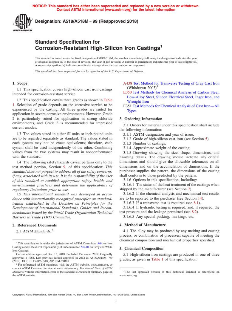
1.2 This specification covers three grades as shown in Table 1. Selection of grade depends on the corrosive service to be experienced by the casting. All three grades are suited for application in severe corrosive environments. However, Grade 2 is particularly suited for application in strong chloride environments, and Grade 3 is recommended for impressed current anodes.
1.3 The values stated in either SI units or inch-pound units are to be regarded separately as standard. The values stated in each system may not be exact equivalents; therefore, each system shall be used independently of the other. Combining values from the two systems may result in nonconformance with the standard.
1.4 The following safety hazards caveat pertains only to the test method portion, Section 9, of this specification: This standard does not purport to address all of the safety concerns, if any, associated with its use. It is the responsibility of the user of this standard to establish appropriate safety, health, and environmental practices and determine the applicability of regulatory limitations prior to use.
1.5 This international standard was developed in accordance with internationally recognized principles on standardization established in the Decision on Principles for the Development of International Standards, Guides and Recommendations issued by the World Trade Organization Technical Barriers to Trade (TBT) Committee.
General Information
Buy Standard
Standards Content (Sample)
NOTICE: This standard has either been superseded and replaced by a new version or withdrawn.
Contact ASTM International (www.astm.org) for the latest information
Designation: A518/A518M −99 (Reapproved 2018)
Standard Specification for
Corrosion-Resistant High-Silicon Iron Castings
This standard is issued under the fixed designationA518/A518M; the number immediately following the designation indicates the year
of original adoption or, in the case of revision, the year of last revision. A number in parentheses indicates the year of last reapproval.
A superscript epsilon (´) indicates an editorial change since the last revision or reapproval.
This standard has been approved for use by agencies of the U.S. Department of Defense.
1. Scope A438 Test Method for Transverse Testing of Gray Cast Iron
(Withdrawn 2003)
1.1 This specification covers high-silicon cast iron castings
E350 Test Methods for Chemical Analysis of Carbon Steel,
intended for corrosion-resistant service.
Low-Alloy Steel, Silicon Electrical Steel, Ingot Iron, and
1.2 This specification covers three grades as shown in Table
Wrought Iron
1. Selection of grade depends on the corrosive service to be
E351 Test Methods for ChemicalAnalysis of Cast Iron—All
experienced by the casting. All three grades are suited for
Types
application in severe corrosive environments. However, Grade
2 is particularly suited for application in strong chloride
3. Ordering Information
environments, and Grade 3 is recommended for impressed
3.1 Orders for material under this specification shall include
current anodes.
the following information:
1.3 The values stated in either SI units or inch-pound units
3.1.1 ASTM designation and year of issue.
are to be regarded separately as standard. The values stated in
3.1.2 Grade of high-silicon cast iron (see Section 5).
each system may not be exact equivalents; therefore, each
3.1.3 Number of castings.
system shall be used independently of the other. Combining
3.1.4 Approximate weight of the casting.
values from the two systems may result in nonconformance
3.1.5 Drawing showing the size, shape, dimensions, and
with the standard.
finishing details. The drawing should indicate any critical
dimensions and should give the allowable tolerances on all
1.4 The following safety hazards caveat pertains only to the
dimensions and on the accumulation of dimensions. If the
test method portion, Section 9, of this specification: This
purchaser supplies the pattern, the dimensions of the casting
standarddoesnotpurporttoaddressallofthesafetyconcerns,
shall conform to those predicted by the pattern.
ifany,associatedwithitsuse.Itistheresponsibilityoftheuser
3.1.6 Options in this specification, including:
of this standard to establish appropriate safety, health, and
3.1.6.1 The status of the heat treatment of the castings when
environmental practices and determine the applicability of
shipped by the manufacturer (see Section 7).
regulatory limitations prior to use.
3.1.6.2 If the chemical analysis and mechanical test results
1.5 This international standard was developed in accor-
are to be reported to the purchaser (see Section 14).
dance with internationally recognized principles on standard-
3.1.6.3 If a transverse test is required (see 8.1).
ization established in the Decision on Principles for the
3.1.6.4 If hydraulic testing is required, and, if required, the
Development of International Standards, Guides and Recom-
test pressure and the leakage permitted (see 8.2).
mendations issued by the World Trade Organization Technical
3.1.6.5 Any special packing, markings, etc.
Barriers to Trade (TBT) Committee.
4. Method of Manufacture
2. Referenced Documents
4.1 The alloy may be produced by any melting and casting
2.1 ASTM Standards:
process, or combination of processes, capable of meeting the
chemical composition and mechanical properties specified.
This specification is under the jurisdiction of ASTM Committee A04 on Iron
CastingsandisthedirectresponsibilityofSubcommitteeA04.01onGreyandWhite
5. Chemical Composition
Iron Castings.
Current edition approved Dec. 15, 2018. Published December 2018. Originally
5.1 High-silicon iron castings are produced in one of three
approved in 1964. Last previous edition approved in 2012 as A518/A518M – 99
grades, as given in Table 1 of this specification.
(2012). DOI: 10.1520/A0518_A0518M-99R18.
For referenced ASTM standards, visit the ASTM website, www.astm.org, or
contact ASTM Customer Service at service@astm.org. For Annual Book of ASTM
Standards volume information, refer to the standard’s Document Summary page on The last approved version of this historical standard is referenced on
the ASTM website. www.astm.org.
Copyright © ASTM International, 100 Barr Harbor Drive, PO Box C700, West Conshohocken, PA 19428-2959. United States
A518/A518M − 99 (2018)
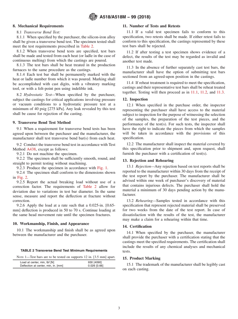
TABLE 1 Chemical Composition
6.4.3 Carbon—Determine carbon in accordance with sec-
Composition, Weight % tions on Carbon, Total, by the Combustion Gravimetric
Element
Grade 1 Grade 2 Grade 3 Method, in Test Methods E350.
Carbon 0.65–1.10 0.75–1.15 0.70–1.10 6.4.4 Manganese:
Manganese 1.50, max 1.50, max 1.50, max
6.4.4.1 Mill, lathe, or pulverize the sample to pass through
Silicon 14.20–14.75 14.20–14.75 14.20–14.75
a 100-mesh sieve.
Chromium 0.50, max 3.25–5.00 3.25–5.00
Molybdenum 0.50, max 0.40–0.60 0.20, max 6.4.4.2 Determine manganese in accordance with the sec-
Copper 0.50, max 0.50, max 0.50, max
tions on Manganese by the Peroxydisulfate-Arsenite Titrimet-
ric Method in Test Methods E350. Add hydrofluoric acid as
required for complete solution of the (HF) sample.
6.4.5 Chromium:
6.4.5.1 Mill, lathe, or pulverize the sample to pass through
6. Chemical Analysis
a 100-mesh sieve.
6.1 Heat Analysis—Chemical analysis of each heat (or each
6.4.5.2 Determine chromium in accordance with the sec-
tap, if from a continuous melting operation) shall be made by
tions on Chromium by the Peroxydisulfate-Oxidation Titrimet-
the manufacturer to determine the percentages of the elements
ric Method in Test Methods E350, except dissolve the sample
specified in Table 1. The analysis shall be made from a test
as follows:
sample cast during the pouring of the heat (or tap). The
(a) Place the appropriate amount of weighed sample into a
chemical composition thus determined shall conform to the
600-mLGriffin beaker or 500-mLvolumetric flask.Add 20 mL
requirements specified for that grade in Table 1.
of nitric acid (HNO ) and carefully add HF, dropwise, until the
reaction ceases. A TFE-fluorocarbon beaker may be used if
6.2 Product Analysis—A product analysis may be made by
desired.
the purchaser from material representing each heat, lot, or
(b) Add30mLof1+1 sulfuric acid (H SO),5mLof
casting. The sample for such analysis shall be taken as desired 2 4
phosphoric acid (H PO ), and boil until light fumes of H SO
by the purchaser. The chemical composition thus determined
3 4 2 4
are present and the sample is completely dissolved.
shall meet the requirements for the grade specified.
(c) Cool the solution, add 150 mL of water, heat to
6.3 Routine Analysis Methods—Spectrometric and other
dissolve if necessary, and continue as in Test Methods E350.
instrumental methods or wet chemical laboratory methods are
6.4.6 Copper:
acceptable for routine and control determinations, but shall be
6.4.6.1 Mill, lathe, or pulverize the sample to pass through
standardizedagainstandgiveessentiallythesameresultsasthe
a 100-mesh sieve.
methods specified in 6.4.
6.4.6.2 Determine the copper in accordance with the sec-
6.4 Reference Analysis Methods:
tions on Copper by the Sulfide Precipitation-Electrodeposition
6.4.1 Silicon:
Gravimetric Method in Test Methods E350,or
6.4.1.1 Analyze samples soluble when processed in accor-
6.4.6.3 Determine the copper in accordance with the sec-
dance with Test Methods E350, by that method, except as
tions on Copper by the Neocuproine Photometric Method, in
follows:
Test Methods E350.Add HF as required for complete solution
(a) The sample weight shall be 0.3 g with a weight
of the sample.
tolerance of 60.1 mg.
7. Heat Treatment
(b) Pulverize one or more pieces of the sample until the
entire material in the piece or pieces passes through a 100-
7.1 High-silicon iron castings are generally used in the
mesh screen.
heat-treated (stress-relieved) condition. Small castings of
(c) Dissolve the sample in 25 mL of perchloric acid.
simple configuration not conducive to high residual stresses
6.4.1.2 Analyze samples that are not soluble when pro-
may be used in the as-cast condition. If the castings are to be
cessed in accordance with 6.4.1.1 in accordance with Annex
supplied in the stress-relieved condition, the purchaser must so
A1.
specify.
6.4.2 Molybdenum:
7.2 At its option, the foundry may heat treat the castings to
6.4.2.1 Mill, lathe, or pulverize the sample to pass through
remove stresses without the purchaser so specifying.
a 100-mesh sieve. If the sample is soluble when processed in
accordance with Test Methods E350, use this method. 7.3 If used, the stress-relieving heat treatment shall be as
6.4.2.2 If the sample is not acid soluble when processed in follows:
accordance with 6.4.2.1, proceed as follows: 7.3.1 Heat at a rate that will not crack the castings.
(a) Use the appropriate weight of sample in accordance 7.3.2 Hold the castings at a minimum temperature of
with6.4.2.1insteadoftheweightgiveninA1.2.3ofAnnexA1. 1600 °F [870 °C] for a minimum period of 1 h/in. [mm] of
(b) Fuse the sample in accordance with A1.2.1 and A1.2.2 maximum section thickness, except that in no case shall the
and A1.2.4 – A1.2.12 of Annex A1. holding period be less than 2 h.
(c) Add the amount of dissolving acid(s), specified in the 7.3.3 Cool the castings to 400 °F [205 °C] maximum at a
sections in Molybdenum by the Photometric Method in Test rate not faster than 100 °F [55 °C]⁄15 min.
Methods E350, heat to fumes of perchloric acid. Proceed in 7.3.4 From 400 °F [205 °C] to ambient temperature, the
accordance with Test Methods E350. castings may be cooled in still ambient air.
A518/A518M − 99 (2018)
8. Mechanical Requirements 11. Number of Tests and Retests
11.1 If a valid test specimen fails to conform to this
8.1 Transverse Bend Test:
specification, two retests shall be made. If either retest fails to
8.1.1 When specified by the purchaser, the silicon-iron alloy
conform to this specification, the castings represented by these
shall be given a transverse bend test.The specimen tested shall
test bars shall be rejected.
meet the test requirements prescribed in Table 2.
8.1.2 When transverse bend tests are specified, test bars
11.2 If after testing a test specimen shows evidence of a
shall be made and tested from each heat (or ladle in the case of
defect, the results of the test may be regarded as invalid and
continuous melting) from which the castings are poured.
another test made.
8.1.3 The test bars shall be heat treated in the production
11.3 In the absence of further separately cast test bars, the
furnaces to the same procedure as the castings.
manufacturer shall have the option of submitting test bars
8.1.4 Each test bar shall be permanently marked with the
sectioned from an agreed-upon position in the castings.
heat or ladle number from which it was poured. Marking shall
11.4 If reheat treatment is required to meet the specification,
be accomplished with cast digits, with a vibratory marking
castingsandtheirrepresentativetestbarsshallbereheattreated
tool, or with a felt-point pen using indelible ink.
together. Testing will then proceed as in 11.1, 11.2, and 11.3.
8.2 Hydrostatic Test—When specified by the purchaser,
subject the castings for critical applications involving pressure 12. Inspection
or vacuum conditions to a hydrostatic pressure test at a
12.1 When specified in the purchase order, the inspector
minimum of 40 psig [275 kPa]. Any leak revealed by this test
representing the purchaser shall have access to the material
shall be cause for rejection of the casting.
subjecttoinspectionforthepurposeofwitnessingtheselection
of the samples, the preparation of the test pieces, and the
9. Transverse Bend Test Method
performance of the test(s). For such tests, the inspector shall
9.1 When a requirement for transverse bend tests has been have the right to indicate the pieces from which the samples
will be taken in accordance with the provisions of this
agreed upon between the purchaser and the manufacturer, the
manufacturer shall test transverse bend bar(s) from each heat. specification.
12.2 The manufacturer shall inspect the material covered by
9.2 ConductthetransversebendtestinaccordancewithTest
this specification prior to shipment and, upon request, shall
Method A438, except as follows:
furnish the purchaser with a certification of test(s).
9.2.1 Do not machine the specimen.
9.2.2 The specimen shall be sufficiently smooth, round, and
13. Rejection and Rehearing
straight to permit testing without machining.
13.1 Rejection—Any rejection based on test reports shall be
9.2.3 Produce the specimen in accordance with Fig. 1.
reported to the manufacturer within 30 days from the receipt of
9.2.4 The specimen shall conform to the dimensions shown
the test report by the purchaser. The manufacturer shall be
in Fig. 2.
advised within one week of purchaser’s discovery of material
9.2.5 Report the actual breaking load without use of a
that contains injurious defects. The purchaser shall hold the
correction factor. The requirements of Table 2 allow for
material a minimum of 30 days pending action by the manu-
deviation due to variations in test bar diameter. In the same
facturer.
sense, measure and report the deflection at fracture without
correction. 13.2 Rehearing—Samples tested in accordance with this
9.2.6 Apply the load at a rate such that a 0.025-in. [0.65- specification that represent rejected material shall be preserved
mm] deflection is produced in 50 to 70 s. Continue loading at for two weeks from the date of the test report. In case of
dissatisfaction with the results of the test, the manufacturer
the same head movement rate until the specimen fractures.
may make a claim for a rehearing within that time.
10. Workmanship, Finish, and Appearance
14. Certification
10.1 The workmanship and finish shall be as agreed upon
14.1 When specified by the purchaser, the manufacturer
between the manufacturer and the purchaser.
shall provide the purchaser with a certification stating that the
castingsmeetthespecifiedrequirements.Thecertificationshall
include the results of any chemical analyses and mechanical
TABLE 2 Transverse Bend Test Minimum Requirements
tests.
NOTE 1—Test bars are to be tested on supports 12 in. [3.5 mm] apart.
15. Product Marking
Load at center, min, lbf [N] 930 [4090]
15.1 Thetrademarkofthemanufacturershallbelegiblycast
Deflection at center, min, in. [mm] 0.026 [0.66]
on each casting.
----------------
...
This document is not an ASTM standard and is intended only to provide the user of an ASTM standard an indication of what changes have been made to the previous version. Because
it may not be technically possible to adequately depict all changes accurately, ASTM recommends that users consult prior editions as appropriate. In all cases only the current version
of the standard as published by ASTM is to be considered the official document.
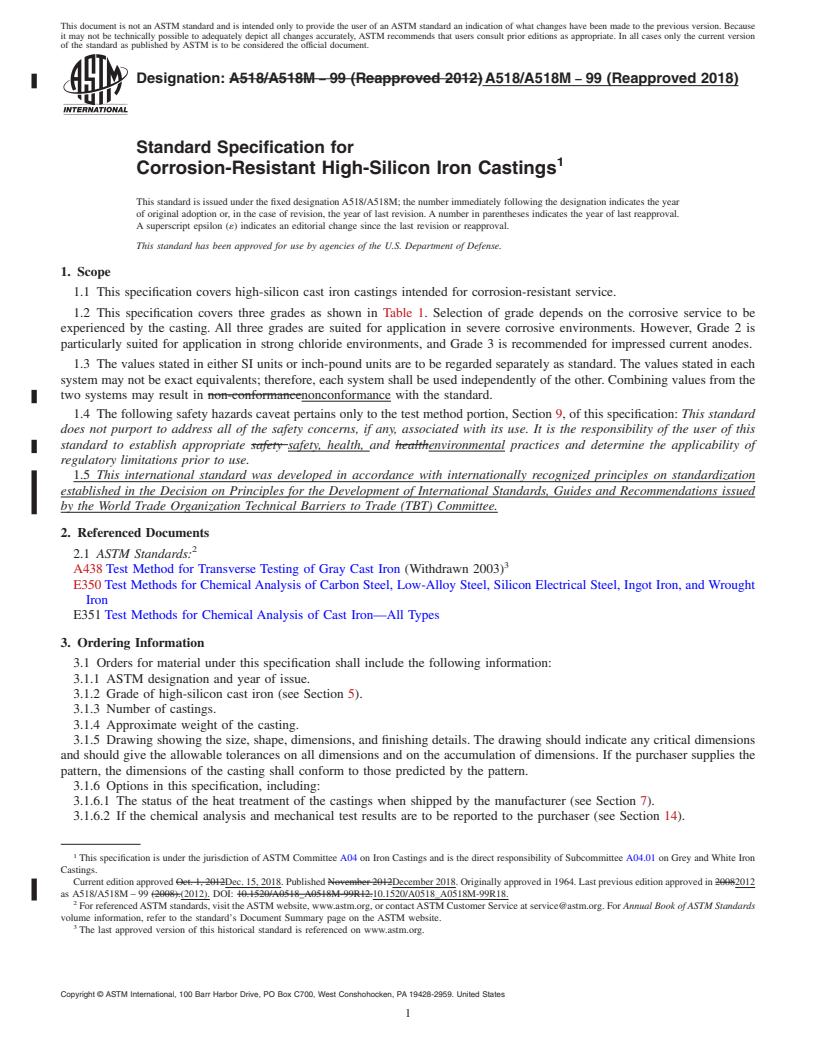
Designation: A518/A518M − 99 (Reapproved 2012) A518/A518M − 99 (Reapproved 2018)
Standard Specification for
Corrosion-Resistant High-Silicon Iron Castings
This standard is issued under the fixed designation A518/A518M; the number immediately following the designation indicates the year
of original adoption or, in the case of revision, the year of last revision. A number in parentheses indicates the year of last reapproval.
A superscript epsilon (´) indicates an editorial change since the last revision or reapproval.
This standard has been approved for use by agencies of the U.S. Department of Defense.
1. Scope
1.1 This specification covers high-silicon cast iron castings intended for corrosion-resistant service.
1.2 This specification covers three grades as shown in Table 1. Selection of grade depends on the corrosive service to be
experienced by the casting. All three grades are suited for application in severe corrosive environments. However, Grade 2 is
particularly suited for application in strong chloride environments, and Grade 3 is recommended for impressed current anodes.
1.3 The values stated in either SI units or inch-pound units are to be regarded separately as standard. The values stated in each
system may not be exact equivalents; therefore, each system shall be used independently of the other. Combining values from the
two systems may result in non-conformancenonconformance with the standard.
1.4 The following safety hazards caveat pertains only to the test method portion, Section 9, of this specification: This standard
does not purport to address all of the safety concerns, if any, associated with its use. It is the responsibility of the user of this
standard to establish appropriate safety safety, health, and healthenvironmental practices and determine the applicability of
regulatory limitations prior to use.
1.5 This international standard was developed in accordance with internationally recognized principles on standardization
established in the Decision on Principles for the Development of International Standards, Guides and Recommendations issued
by the World Trade Organization Technical Barriers to Trade (TBT) Committee.
2. Referenced Documents
2.1 ASTM Standards:
A438 Test Method for Transverse Testing of Gray Cast Iron (Withdrawn 2003)
E350 Test Methods for Chemical Analysis of Carbon Steel, Low-Alloy Steel, Silicon Electrical Steel, Ingot Iron, and Wrought
Iron
E351 Test Methods for Chemical Analysis of Cast Iron—All Types
3. Ordering Information
3.1 Orders for material under this specification shall include the following information:
3.1.1 ASTM designation and year of issue.
3.1.2 Grade of high-silicon cast iron (see Section 5).
3.1.3 Number of castings.
3.1.4 Approximate weight of the casting.
3.1.5 Drawing showing the size, shape, dimensions, and finishing details. The drawing should indicate any critical dimensions
and should give the allowable tolerances on all dimensions and on the accumulation of dimensions. If the purchaser supplies the
pattern, the dimensions of the casting shall conform to those predicted by the pattern.
3.1.6 Options in this specification, including:
3.1.6.1 The status of the heat treatment of the castings when shipped by the manufacturer (see Section 7).
3.1.6.2 If the chemical analysis and mechanical test results are to be reported to the purchaser (see Section 14).
This specification is under the jurisdiction of ASTM Committee A04 on Iron Castings and is the direct responsibility of Subcommittee A04.01 on Grey and White Iron
Castings.
Current edition approved Oct. 1, 2012Dec. 15, 2018. Published November 2012December 2018. Originally approved in 1964. Last previous edition approved in 20082012
as A518/A518M – 99 (2008).(2012). DOI: 10.1520/A0518_A0518M-99R12.10.1520/A0518_A0518M-99R18.
For referenced ASTM standards, visit the ASTM website, www.astm.org, or contact ASTM Customer Service at service@astm.org. For Annual Book of ASTM Standards
volume information, refer to the standard’s Document Summary page on the ASTM website.
The last approved version of this historical standard is referenced on www.astm.org.
Copyright © ASTM International, 100 Barr Harbor Drive, PO Box C700, West Conshohocken, PA 19428-2959. United States
A518/A518M − 99 (2018)
TABLE 1 Chemical Composition
Composition, Weight %
Element
Grade 1 Grade 2 Grade 3
Carbon 0.65–1.10 0.75–1.15 0.70–1.10
Manganese 1.50, max 1.50, max 1.50, max
Silicon 14.20–14.75 14.20–14.75 14.20–14.75
Chromium 0.50, max 3.25–5.00 3.25–5.00
Molybdenum 0.50, max 0.40–0.60 0.20, max
Copper 0.50, max 0.50, max 0.50, max
3.1.6.3 If a transverse test is required (see 8.1).
3.1.6.4 If hydraulic testing is required, and, if required, the test pressure and the leakage permitted (see 8.2).
3.1.6.5 Any special packing, markings, etc.
4. Method of Manufacture
4.1 The alloy may be produced by any melting and casting process, or combination of processes, capable of meeting the
chemical composition and mechanical properties specified.
5. Chemical Composition
5.1 High-silicon iron castings are produced in one of three grades, as given in Table 1 of this specification.
6. Chemical Analysis
6.1 Heat Analysis—Chemical analysis of each heat (or each tap, if from a continuous melting operation) shall be made by the
manufacturer to determine the percentages of the elements specified in Table 1. The analysis shall be made from a test sample cast
during the pouring of the heat (or tap). The chemical composition thus determined shall conform to the requirements specified for
that grade in Table 1.
6.2 Product Analysis—A product analysis may be made by the purchaser from material representing each heat, lot, or casting.
The sample for such analysis shall be taken as desired by the purchaser. The chemical composition thus determined shall meet the
requirements for the grade specified.
6.3 Routine Analysis Methods—Spectrometric and other instrumental methods or wet chemical laboratory methods are
acceptable for routine and control determinations, but shall be standardized against and give essentially the same results as the
methods specified in 6.4.
6.4 Reference Analysis Methods:
6.4.1 Silicon:
6.4.1.1 Analyze samples soluble when processed in accordance with Test Methods E350, by that method, except as follows:
(a) The sample weight shall be 0.3 g with a weight tolerance of 60.1 mg.
(b) Pulverize one or more pieces of the sample until the entire material in the piece or pieces passes through a 100-mesh screen.
(c) Dissolve the sample in 25 mL of perchloric acid.
6.4.1.2 Analyze samples that are not soluble when processed in accordance with 6.4.1.1 in accordance with Annex A1.
6.4.2 Molybdenum:
6.4.2.1 Mill, lathe, or pulverize the sample to pass through a 100-mesh sieve. If the sample is soluble when processed in
accordance with Test Methods E350, use this method.
6.4.2.2 If the sample is not acid-soluble acid soluble when processed in accordance with 6.4.2.1, proceed as follows:
(a) Use the appropriate weight of sample in accordance with 6.4.2.1 instead of the weight given in A1.2.3 of Annex A1.
(b) Fuse the sample in accordance with A1.2.1 and A1.2.2 and A1.2.4 – A1.2.12 of Annex A1.
(c) Add the amount of dissolving acid(s), specified in the sections in Molybdenum by the Photometric Method in Test Methods
E350, heat to fumes of perchloric acid. Proceed in accordance with Test Methods E350.
6.4.3 Carbon—Determine carbon in accordance with sections on Carbon, Total, by the Combustion Gravimetric Method, in Test
Methods E350.
6.4.4 Manganese:
6.4.4.1 Mill, lathe, or pulverize the sample to pass through a 100-mesh sieve.
6.4.4.2 Determine manganese in accordance with the sections on Manganese by the Peroxydisulfate-Arsenite Titrimetric
Method in Test Methods E350. Add hydrofluoric acid as required for complete solution of the (HF) sample.
6.4.5 Chromium:
6.4.5.1 Mill, lathe, or pulverize the sample to pass through a 100-mesh sieve.
6.4.5.2 Determine chromium in accordance with the sections on Chromium by the Peroxydisulfate-Oxidation Titrimetric
Method in Test Methods E350, except dissolve the sample as follows:
A518/A518M − 99 (2018)
(a) Place the appropriate amount of weighed sample into a 600-mL Griffin beaker or 500-mL volumetric flask. Add 20 mL
of nitric acid (HNO ) and carefully add HF, dropwise, until the reaction ceases. A TFE-fluorocarbon beaker may be used if desired.
(b) Add 30 mL of 1 + 1 sulfuric acid (H SO ), 5 mL of phosphoric acid (H PO ), and boil until light fumes of H SO are
2 4 3 4 2 4
present and the sample is completely dissolved.
(c) Cool the solution, add 150 mL of water, heat to dissolve if necessary, and continue as in Test Methods E350.
6.4.6 Copper:
6.4.6.1 Mill, lathe, or pulverize the sample to pass through a 100-mesh sieve.
6.4.6.2 Determine the copper in accordance with the sections on Copper by the Sulfide Precipitation-Electrodeposition
Gravimetric Method in Test Methods E350, or
6.4.6.3 Determine the copper in accordance with the sections on Copper by the Neocuproine Photometric Method, in Test
Methods E350. Add HF as required for complete solution of the sample.
7. Heat Treatment
7.1 High-silicon iron castings are generally used in the heat-treated (stress-relieved) condition. Small castings of simple
configuration not conducive to high-residual high residual stresses may be used in the as-cast condition. If the castings are to be
supplied in the stress-relieved condition, the purchaser must so specify.
7.2 At its option, the foundry may heat treat the castings to remove stresses without the purchaser so specifying.
7.3 If used, the stress-relieving heat treatment shall be as follows:
7.3.1 Heat at a rate that will not crack the castings.
7.3.2 Hold the castings at a minimum temperature of 1600°F [870°C]1600 °F [870 °C] for a minimum period of 1 h/in. [mm]
of maximum section thickness, except that in no case shall the holding period be less than 2 h.
7.3.3 Cool the castings to 400°F [205°C]400 °F [205 °C] maximum at a rate not faster than 100°F [55°C]/15100 °F [55 °C] ⁄15
min.
7.3.4 From 400°F [205°C]400 °F [205 °C] to ambient temperature, the castings may be cooled in still ambient air.
8. Mechanical Requirements
8.1 Transverse Bend Test:
8.1.1 When specified by the purchaser, the silicon-iron alloy shall be given a transverse bend test. The specimen tested shall
meet the test requirements prescribed in Table 2.
8.1.2 When transverse bend tests are specified, test bars shall be made and tested from each heat (or ladle in the case of
continuous melting) from which the castings are poured.
8.1.3 The test bars shall be heat treated in the production furnaces to the same procedure as the castings.
8.1.4 Each test bar shall be permanently marked with the heat or ladle number from which it was poured. Marking shall be
accomplished with cast digits, with a vibratory marking tool, or with a felt-point pen using indelible ink.
8.2 Hydrostatic Test—When specified by the purchaser, subject the castings for critical applications involving pressure or
vacuum conditions to a hydrostatic pressure test at a minimum of 40 psig [275 kPa]. Any leak revealed by this test shall be cause
for rejection of the casting.
9. Transverse Bend Test Method
9.1 When a requirement for transverse bend tests has been agreed upon between the purchaser and the manufacturer, the
manufacturer shall test transverse bend bar(s) from each heat.
9.2 Conduct the transverse bend test in accordance with Test Method A438, except as follows:
9.2.1 Do not machine the specimen.
9.2.2 The specimen shall be sufficiently smooth, round, and straight to permit testing without machining.
9.2.3 Produce the specimen in accordance with Fig. 1.
9.2.4 The specimen shall conform to the dimensions shown in Fig. 2.
9.2.5 Report the actual breaking load without use of a correction factor. The requirements of Table 2 allow for deviation due
to variations in test bar diameter. In the same sense, measure and report the deflection at fracture without correction.
9.2.6 Apply the load at a rate such that a 0.025-in. [0.65-mm] deflection is produced in 50 to 70 s. Continue loading at the same
head-movement head movement rate until the specimen fractures.
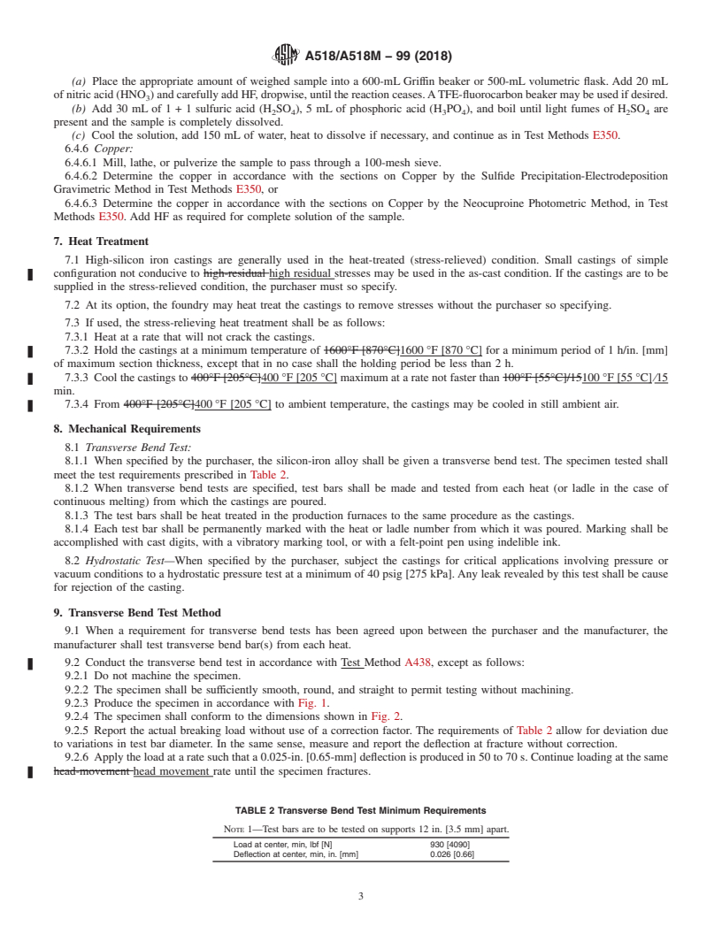
TABLE 2 Transverse Bend Test Minimum Requirements
NOTE 1—Test bars are to be tested on supports 12 in. [3.5 mm] apart.
Load at center, min, lbf [N] 930 [4090]
Deflection at center, min, in. [mm] 0.026 [0.66]
A518/A518M − 99 (2018)
FIG. 1 Suggested Pattern for Transverse Bend Test Bar, Cast Horizontally, 1.20 in. [30.5 mm] in Diameter
NOTE 1—It is recommended that the casting be mold-cooled mold cooled to below 1000°F [540°C]1000 °F [540 °C] before shakeout, and that the test
bars be stress-relieved stress relieved before transverse testing.
FIG. 2 Transverse Bend Test Bar Dimensions
10. Workmanship, Finish, and Appearance
10.1 The workmanship and finish shall be as agreed upon between the manufacturer and the purchaser.
11. Number of Tests and Retests
11.1 If a valid test specimen fails to conform to this specification, two retests shall be made. If either retest fails to conform to
this specification, the castings represented by these test bars shall be rejected.
11.2 If after testing,testing a test specimen shows evidence of a defect, the results of the test may be regarded as invalid and
another test made.
11.3 In the absence of further separately cast test bars, the manufacturer shall have the option of submitting test bars sectioned
from an agreed-upon position in the castings.
11.4 If reheat treatment is required to meet the specification, castings and their representative test bars shall be reheat treated
together. Testing will then proceed as in 11.1, 11.2, and 11.3.
A518/A518M − 99 (2018)
12. Inspection
12.1 When specified in the purchase order, the inspector representing the purchaser shall have access to the material subject to
inspection for the purpose of witnessing the selection of the samples, the preparation of the test pieces, and the performance of
the test(s). For such tests, the inspector shall have the right to indicate the pieces from which the samples will be taken in
accordance with the provisions of this specification.
12.2 The manufacturer shall inspect the material covered by this specification prior to shipment and, upon request, shall furnish
the p
...
Questions, Comments and Discussion
Ask us and Technical Secretary will try to provide an answer. You can facilitate discussion about the standard in here.