


ASTM A476/A476M-00(2018)
(Specification)Standard Specification for Ductile Iron Castings for Paper Mill Dryer Rolls
Standard Specification for Ductile Iron Castings for Paper Mill Dryer Rolls
ABSTRACT
This specification covers ductile iron castings for use in pressure containing paper mill dryer rolls. The castings shall be stress relieved through heat treatment and shall undergo chemical analysis and conform to the required chemical composition in total carbon, silicon, phosphorus, and sulfur. Tension test specimens shall be obtained from test coupons poured from the same iron as the castings represented and shall conform to the prescribed mechanical properties such as yield strength, tensile strength, and elongation. Hardness test shall be conducted on the material and shall meet the required Brinell hardness value.
SCOPE
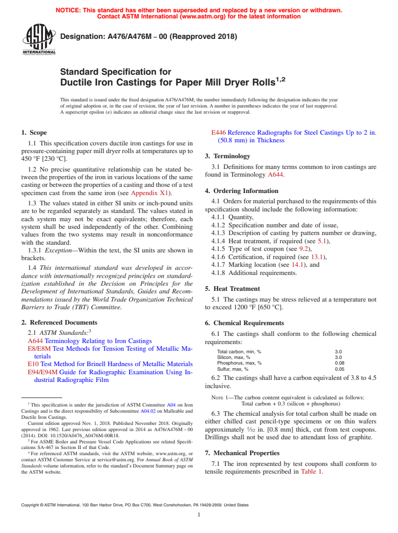
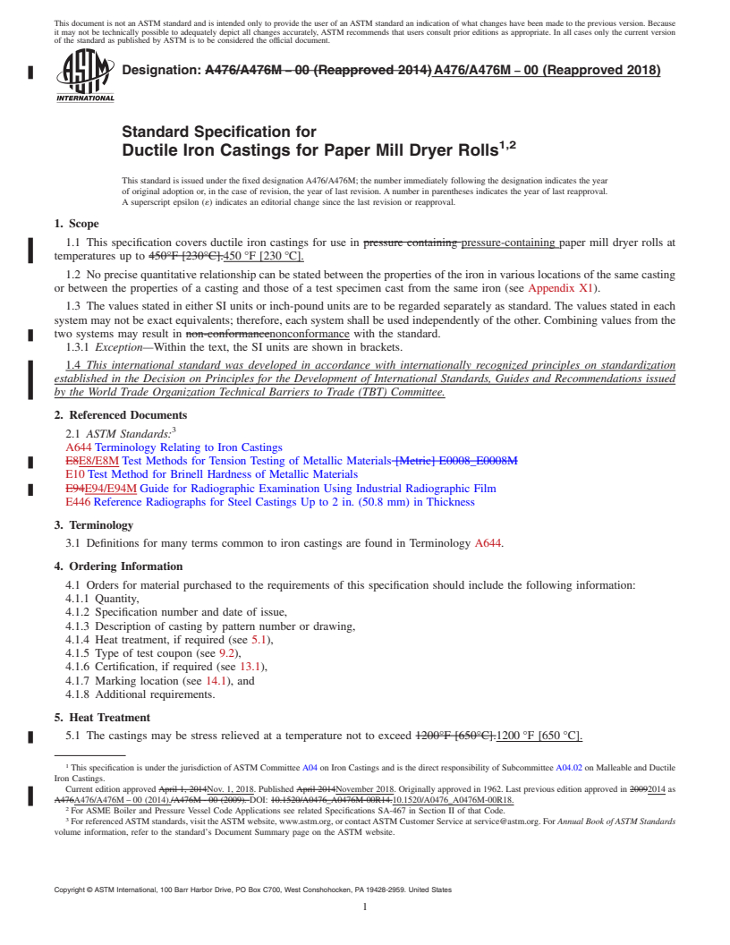
1.1 This specification covers ductile iron castings for use in pressure-containing paper mill dryer rolls at temperatures up to 450 °F [230 °C].
1.2 No precise quantitative relationship can be stated between the properties of the iron in various locations of the same casting or between the properties of a casting and those of a test specimen cast from the same iron (see Appendix X1).
1.3 The values stated in either SI units or inch-pound units are to be regarded separately as standard. The values stated in each system may not be exact equivalents; therefore, each system shall be used independently of the other. Combining values from the two systems may result in nonconformance with the standard.
1.3.1 Exception—Within the text, the SI units are shown in brackets.
1.4 This international standard was developed in accordance with internationally recognized principles on standardization established in the Decision on Principles for the Development of International Standards, Guides and Recommendations issued by the World Trade Organization Technical Barriers to Trade (TBT) Committee.
General Information
Buy Standard
Standards Content (Sample)
NOTICE: This standard has either been superseded and replaced by a new version or withdrawn.
Contact ASTM International (www.astm.org) for the latest information
Designation: A476/A476M −00 (Reapproved 2018)
Standard Specification for
1,2
Ductile Iron Castings for Paper Mill Dryer Rolls
This standard is issued under the fixed designationA476/A476M; the number immediately following the designation indicates the year
of original adoption or, in the case of revision, the year of last revision. A number in parentheses indicates the year of last reapproval.
A superscript epsilon (´) indicates an editorial change since the last revision or reapproval.
1. Scope E446 Reference Radiographs for Steel Castings Up to 2 in.
(50.8 mm) in Thickness
1.1 This specification covers ductile iron castings for use in
pressure-containing paper mill dryer rolls at temperatures up to
3. Terminology
450 °F [230 °C].
3.1 Definitions for many terms common to iron castings are
1.2 No precise quantitative relationship can be stated be-
found in Terminology A644.
tweenthepropertiesoftheironinvariouslocationsofthesame
castingorbetweenthepropertiesofacastingandthoseofatest
4. Ordering Information
specimen cast from the same iron (see Appendix X1).
4.1 Ordersformaterialpurchasedtotherequirementsofthis
1.3 The values stated in either SI units or inch-pound units
specification should include the following information:
are to be regarded separately as standard. The values stated in
4.1.1 Quantity,
each system may not be exact equivalents; therefore, each
4.1.2 Specification number and date of issue,
system shall be used independently of the other. Combining
4.1.3 Description of casting by pattern number or drawing,
values from the two systems may result in nonconformance
4.1.4 Heat treatment, if required (see 5.1),
with the standard.
4.1.5 Type of test coupon (see 9.2),
1.3.1 Exception—Within the text, the SI units are shown in
4.1.6 Certification, if required (see 13.1),
brackets.
4.1.7 Marking location (see 14.1), and
1.4 This international standard was developed in accor-
4.1.8 Additional requirements.
dance with internationally recognized principles on standard-
ization established in the Decision on Principles for the
5. Heat Treatment
Development of International Standards, Guides and Recom-
mendations issued by the World Trade Organization Technical 5.1 The castings may be stress relieved at a temperature not
Barriers to Trade (TBT) Committee. to exceed 1200 °F [650 °C].
2. Referenced Documents
6. Chemical Requirements
2.1 ASTM Standards:
6.1 The castings shall conform to the following chemical
A644 Terminology Relating to Iron Castings
requirements:
E8/E8M Test Methods for Tension Testing of Metallic Ma-
Total carbon, min, % 3.0
terials
Silicon, max, % 3.0
Phosphorus, max, % 0.08
E10 Test Method for Brinell Hardness of Metallic Materials
Sulfur, max, % 0.05
E94/E94M Guide for Radiographic Examination Using In-
6.2 The castings shall have a carbon equivalent of 3.8 to 4.5
dustrial Radiographic Film
inclusive.
NOTE 1—The carbon content equivalent is calculated as follows:
Total carbon + 0.3 (silicon + phosphorus)
This specification is under the jurisdiction of ASTM Committee A04 on Iron
Castings and is the direct responsibility of Subcommittee A04.02 on Malleable and
6.3 The chemical analysis for total carbon shall be made on
Ductile Iron Castings.
either chilled cast pencil-type specimens or on thin wafers
Current edition approved Nov. 1, 2018. Published November 2018. Originally
approved in 1962. Last previous edition approved in 2014 as A476/A476M – 00
approximately ⁄32 in. [0.8 mm] thick, cut from test coupons.
(2014). DOI: 10.1520/A0476_A0476M-00R18.
Drillings shall not be used due to attendant loss of graphite.
For ASME Boiler and Pressure Vessel Code Applications see related Specifi-
cations SA-467 in Section II of that Code.
For referenced ASTM standards, visit the ASTM website, www.astm.org, or 7. Mechanical Properties
contact ASTM Customer Service at service@astm.org. For Annual Book of ASTM
7.1 The iron represented by test coupons shall conform to
Standards volume information, refer to the standard’s Document Summary page on
the ASTM website. tensile requirements prescribed in Table 1.
Copyright © ASTM International, 100 Barr Harbor Drive, PO Box C700, West Conshohocken, PA 19428-2959. United States
A476/A476M − 00 (2018)
TABLE 1 Tensile Requirements
Test Coupon Section Thickness 1 in. [25 mm] 3 in. [75 mm]
Tensile strength, min, ksi [MPa] 80 [555] 80 [555]
Yield strength, min, ksi [MPa] 60 [415] 60 [415]
Elongation in 2 in. [50 mm], min, % 3.0 [3.0] 1.0 [1.0]
7.2 The yield strength prescribed in Table 1 may be deter-
mined by any of the approved procedures described in 7.3 of
Test Methods E8/E8M.
7.3 The Brinell hardness of the material shall be a minimum
of 201 HB. Hardness tests shall be conducted in accordance
with Test Method E10, using a 3000-kgf load. The test may be
made on either the casting or on a test coupon representing the
casting.
8. Workmanship, Finish, and Appearance
8.1 The castings shall conform to the dimensions on the
NOTE 1—The length of keel block shall be 6 in. [150 mm].
drawings furnished by the purchaser or, if no drawing has been
FIG. 2 Keel Block for Test Coupons
provided, to the dimensions predicated by the pattern supplied
by the purchaser. Surfaces of the castings shall be free of
adheringsand.Runners,risers,fins,andotherextraneousmetal
shall be removed.
9.3 The test coupons shall be cast in open molds made of
suitable core sand with a minimum 1 ⁄2 in. [38 mm] of sand for
9. Sampling
the 1-in. [25-mm] size and 3 in. [75 mm] of sand for the 3-in.
[75-mm]size.Thecouponsshallbeleftinthemolduntilblack.
9.1 Test coupons shall be poured from the same iron as the
castings represented.
9.4 Table 2 shows the equivalent geometrical shapes with
various dimensions and the equivalent “Y” block, based on
9.2 Test coupons shall be cast either to the “Y” block size
cooling rates, and may be used as a guide for selection of the
and shape shown in Fig. 1 or to the dimensions of the 1-in.
proper “Y” block to be specified to represent the casting.
[25-mm] keel block shown in Fig. 2. The type of test coupon
and, when selected, the size of the “Y” block shall be specified
9.5 Whenthecastingsareheattreated,thetestcouponsshall
by the purchaser.
be heat treated with the castings they represent.
10. Tension Test
10.1 Tension test specimens shall be obtained from test
coupons shown in either Fig. 1 or Fig. 2, and machined to the
dimensions shown in Fig. 3. Test coupons cast as “Y” blocks
(Fig. 1) shall be sectioned as shown in Fig. 4.
10.2 One tension test shall be performed for each casting.
10.3 If any specimen shows defective machining or flaws, it
may be discarded and another substituted from the same
casting represented.
10.4 If an apparently sound test specimen fails to conform
to the tensile requirements, two retests may be made. If either
“Y” Block Size retest fails to conform to the requirements specified, the
For Castings of Thickness For Castings of Thickness castings shall be rejected.
1 1 1
Dimensions ⁄2 in. to 1 ⁄2 in. of 1 ⁄2 in. [40 mm] and
[12.5 to 40 mm] Over
in. [mm] in. [mm]
TABLE 2 Equivalent Geometric Shapes Corresponding to “Y”
A 1 [25] 3 [75]
Blocks
B1 ⁄8 [55] 5 [125]
C 3 [75] 4 [100]
Infinite Plate
“Y” Block Round Diameter, Cube Edge,
D 6 [150] 8 [200]
Thickness,
Size, in. [mm] in. [mm] in. [mm]
E 7 [175] 7 [175]
in. [mm]
approx approx
1 [25] 0.9 [22.5] 1.75 [44] 2.75 [44]
3 [75] 1.6 [40] 3.1 [78] 4.8 [120]
FIG. 1 “Y” Blocks for Test Coupons
A476/A476M − 00 (2018)
11.1.6 The thickness of any repaired section in relation to
the size of plug used shall be not less than that given in Table
3.
11.1.7 The minimum radius of curvature of the repaired
section of the cylinder in relation to the size of plug used shall
be not less than that given in Table 4.
11.1.8 A repaired area may consist of a maximum of three
plugs with a spacing such that the distance between adjacent
plugs shall not be less than those listed in Table 5. Adjacent
areas of repair, in which each contains
...
This document is not an ASTM standard and is intended only to provide the user of an ASTM standard an indication of what changes have been made to the previous version. Because
it may not be technically possible to adequately depict all changes accurately, ASTM recommends that users consult prior editions as appropriate. In all cases only the current version
of the standard as published by ASTM is to be considered the official document.
Designation: A476/A476M − 00 (Reapproved 2014) A476/A476M − 00 (Reapproved 2018)
Standard Specification for
1,2
Ductile Iron Castings for Paper Mill Dryer Rolls
This standard is issued under the fixed designation A476/A476M; the number immediately following the designation indicates the year
of original adoption or, in the case of revision, the year of last revision. A number in parentheses indicates the year of last reapproval.
A superscript epsilon (´) indicates an editorial change since the last revision or reapproval.
1. Scope
1.1 This specification covers ductile iron castings for use in pressure containing pressure-containing paper mill dryer rolls at
temperatures up to 450°F [230°C].450 °F [230 °C].
1.2 No precise quantitative relationship can be stated between the properties of the iron in various locations of the same casting
or between the properties of a casting and those of a test specimen cast from the same iron (see Appendix X1).
1.3 The values stated in either SI units or inch-pound units are to be regarded separately as standard. The values stated in each
system may not be exact equivalents; therefore, each system shall be used independently of the other. Combining values from the
two systems may result in non-conformancenonconformance with the standard.
1.3.1 Exception—Within the text, the SI units are shown in brackets.
1.4 This international standard was developed in accordance with internationally recognized principles on standardization
established in the Decision on Principles for the Development of International Standards, Guides and Recommendations issued
by the World Trade Organization Technical Barriers to Trade (TBT) Committee.
2. Referenced Documents
2.1 ASTM Standards:
A644 Terminology Relating to Iron Castings
E8E8/E8M Test Methods for Tension Testing of Metallic Materials [Metric] E0008_E0008M
E10 Test Method for Brinell Hardness of Metallic Materials
E94E94/E94M Guide for Radiographic Examination Using Industrial Radiographic Film
E446 Reference Radiographs for Steel Castings Up to 2 in. (50.8 mm) in Thickness
3. Terminology
3.1 Definitions for many terms common to iron castings are found in Terminology A644.
4. Ordering Information
4.1 Orders for material purchased to the requirements of this specification should include the following information:
4.1.1 Quantity,
4.1.2 Specification number and date of issue,
4.1.3 Description of casting by pattern number or drawing,
4.1.4 Heat treatment, if required (see 5.1),
4.1.5 Type of test coupon (see 9.2),
4.1.6 Certification, if required (see 13.1),
4.1.7 Marking location (see 14.1), and
4.1.8 Additional requirements.
5. Heat Treatment
5.1 The castings may be stress relieved at a temperature not to exceed 1200°F [650°C].1200 °F [650 °C].
This specification is under the jurisdiction of ASTM Committee A04 on Iron Castings and is the direct responsibility of Subcommittee A04.02 on Malleable and Ductile
Iron Castings.
Current edition approved April 1, 2014Nov. 1, 2018. Published April 2014November 2018. Originally approved in 1962. Last previous edition approved in 20092014 as
A476A476/A476M – 00 (2014)./A476M - 00 (2009). DOI: 10.1520/A0476_A0476M-00R14.10.1520/A0476_A0476M-00R18.
For ASME Boiler and Pressure Vessel Code Applications see related Specifications SA-467 in Section II of that Code.
For referenced ASTM standards, visit the ASTM website, www.astm.org, or contact ASTM Customer Service at service@astm.org. For Annual Book of ASTM Standards
volume information, refer to the standard’s Document Summary page on the ASTM website.
Copyright © ASTM International, 100 Barr Harbor Drive, PO Box C700, West Conshohocken, PA 19428-2959. United States
A476/A476M − 00 (2018)
6. Chemical Requirements
6.1 The castings shall conform to the following chemical requirements:
Total carbon, min, % 3.0
Silicon, max, % 3.0
Phosphorus, max, % 0.08
Sulfur, max, % 0.05
6.2 The castings shall have a carbon equivalent of 3.8 to 4.5 inclusive.
NOTE 1—The carbon content equivalent is calculated as follows:
Total carbon + 0.3 (silicon + phosphorus)
6.3 The chemical analysis for total carbon shall be made on either chilled cast pencil-type specimens or on thin wafers
approximately ⁄32 in. [0.8 mm] thick, cut from test coupons. Drillings shall not be used due to attendant loss of graphite.
7. Mechanical Properties
7.1 The iron represented by test coupons shall conform to tensile requirements prescribed in Table 1.
7.2 The yield strength prescribed in Table 1 may be determined by any of the approved procedures described in 7.3 of Test
Methods E8E8/E8M.
7.3 The Brinell hardness of the material shall be a minimum of 201 HB. Hardness tests shall be conducted in accordance with
Test Method E10, using a 3000-kgf load. The test may be made on either the casting or on a test coupon representing the casting.
8. Workmanship, Finish, and Appearance
8.1 The castings shall conform to the dimensions on the drawings furnished by the purchaser, orpurchaser or, if no drawing has
been provided, to the dimensions predicated by the pattern supplied by the purchaser. Surfaces of the castings shall be free of
adhering sand. Runners, risers, fins, and other extraneous metal shall be removed.
9. Sampling
9.1 Test coupons shall be poured from the same iron as the castings represented.
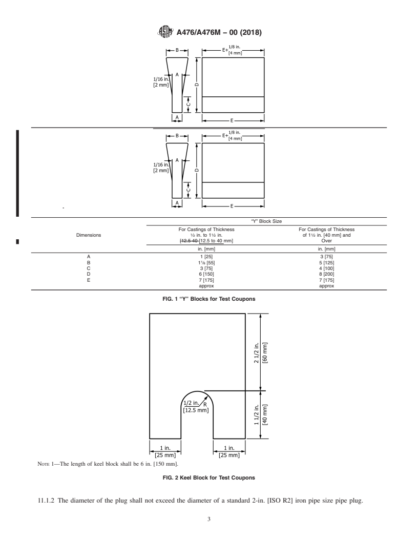
9.2 Test coupons shall be cast either to the “Y” block size and shape shown in Fig. 1 or to the dimensions of the 1-in. [25-mm]
keel block shown in Fig. 2. The type of test coupon and, when selected, the size of the “Y” block shall be specified by the
purchaser.
9.3 The test coupons shall be cast in open molds made of suitable core sand with a minimum 1 ⁄2 in. [38 mm] of sand for the
1-in. [25 mm] [25-mm] size and 3 in. [75 mm] of sand for the 3-in. [75-mm] size. The coupons shall be left in the mold until black.
9.4 Table 2 shows the equivalent geometrical shapes with various dimensions and the equivalent “Y” block, based on cooling
rates, and may be used as a guide for selection of the proper “Y” block to be specified to represent the casting.
9.5 When the castings are heat treated, the test coupons shall be heat treated with the castings they represent.
10. Tension Test
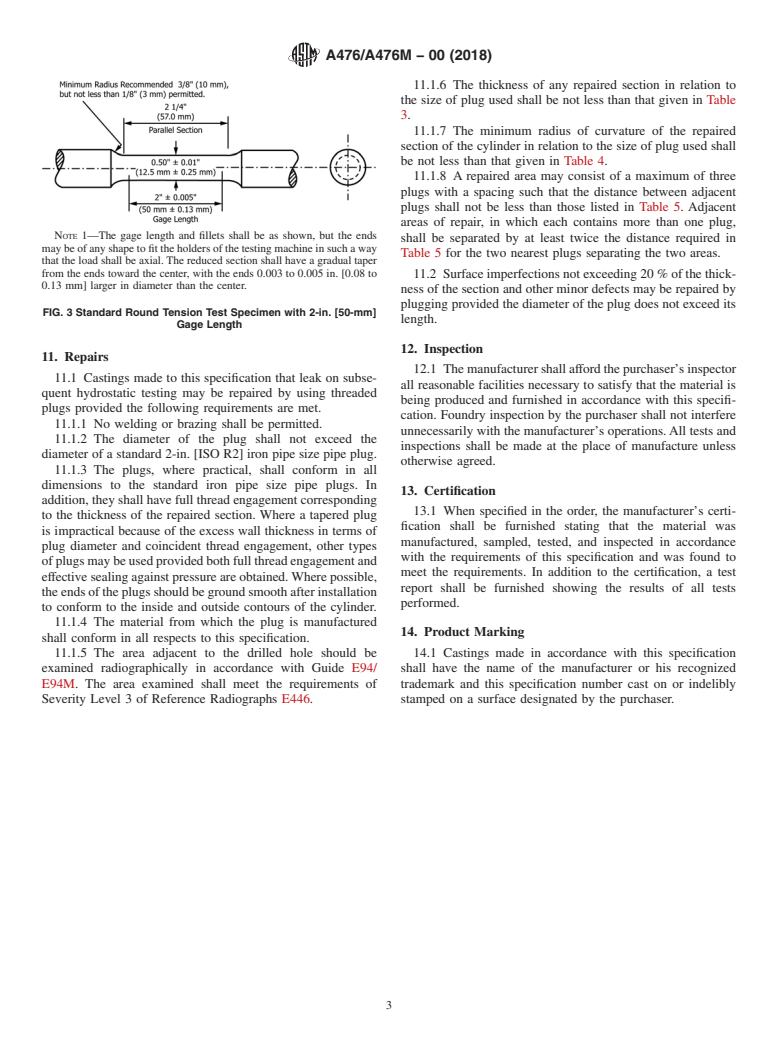
10.1 Tension test specimens shall be obtained from test coupons shown in either Fig. 1 or Fig. 2, and machined to the
dimensions shown in Fig. 3. Test coupons cast as “Y” blocks (Fig. 1) shall be sectioned as shown in Fig. 4.
10.2 One tension test shall be performed for each casting.
10.3 If any specimen shows defective machining or flaws, it may be discarded and another substituted from the same casting
represented.
10.4 If an apparently sound test specimen fails to conform to the tensile requirements, two retests may be made. If either retest
fails to conform to the requirements specified, the castings shall be rejected.
11. Repairs
11.1 Castings made to this specification that leak on subsequent hydrostatic testing may be repaired by using threaded plugs
provided the following requirements are met.
11.1.1 No welding or brazing shall be permitted.
TABLE 1 Tensile Requirements
Test Coupon Section Thickness 1 in. [25 mm] 3 in. [75 mm]
Tensile strength, min, ksi [MPa] 80 [555] 80 [555]
Yield strength, min, ksi [MPa] 60 [415] 60 [415]
Elongation in 2 in. [50 mm], min, % 3.0 [3.0] 1.0 [1.0]
A476/A476M − 00 (2018)
“Y” Block Size
For Castings of Thickness For Castings of Thickness
1 1 1
Dimensions ⁄2 in. to 1 ⁄2 in. of 1 ⁄2 in. [40 mm] and
[12.5-40 [12.5 to 40 mm] Over
in. [mm] in. [mm]
A 1 [25] 3 [75]
B 1 ⁄8 [55] 5 [125]
C 3 [75] 4 [100]
D 6 [150] 8 [200]
E 7 [175] 7 [175]
approx approx
FIG. 1 “Y” Blocks for Test Coupons
NOTE 1—The length of keel block shall be 6 in. [150 mm].
FIG. 2 Keel Block for Test Coupons
11.1.2 The diameter of the plug shall not exceed the diameter of a standard 2-in. [ISO R2] iron pipe size pipe plug.
A476/A476M − 00 (2018)
TABLE 2 Equivalent Geometric Shapes Corresponding to “Y”
Blocks
Infinite Plate
“Y” Block Round Diameter, Cube Edge,
Thickness,
Size, in. [mm] in. [mm] in. [mm]
in. [mm]
1 [25] 0.9 [22.5] 1.75 [44] 2.75 [44]
3 [75] 1.6 [40] 3.1 [78
...
Questions, Comments and Discussion
Ask us and Technical Secretary will try to provide an answer. You can facilitate discussion about the standard in here.