


ASTM D2307-07a(2013)
(Test Method)Standard Test Method for Thermal Endurance of Film-Insulated Round Magnet Wire
Standard Test Method for Thermal Endurance of Film-Insulated Round Magnet Wire
SIGNIFICANCE AND USE
5.1 This test method is useful in determining the thermal endurance characteristics and thermal indices of film-insulated round magnet wire in air (see 1.3) (see Test Method D3251). This test method is used as a screening test before making tests of more complex systems or functional evaluation. It is also used where complete functional systems testing is not feasible.
5.2 Experience has shown that film-insulated wire and electrical insulating varnishes or resins can affect one another during the thermal exposure process. Test Method D3251 provides indications on the thermal endurance for a combination of insulating varnish or resin and film insulated wire. It is possible that interaction between varnish or resin and film insulation will increase or decrease the relative thermal life of the varnish and film insulated wire combination compared with the life of the film insulated wire tested without varnish.
5.3 The conductor type or the surface condition of the conductor will affect the thermal endurance of film-insulated magnet wire. This test method is used to determine the thermal endurance characteristics of film insulation on various kinds of conductors. The use of sizes other than those specified in 7.1.1 is permissible but is not recommended for determining thermal endurance characteristics.
5.4 The temperature index determined by this test method is a nominal or relative value expressed in degrees Celsius at 20 000 h. It is to be used for comparison purposes only and is not intended to represent the temperature at which the film insulated wire could be operated.
5.5 There are many factors that influence the results obtained with this test method. Among the more obvious are the following:
5.5.1 Wire size and film thickness.
5.5.2 Moisture conditions during proof voltage tests.
5.5.3 Oven construction:
5.5.3.1 Velocity of air.
5.5.3.2 Amount of replacement air.
5.5.3.3 Elimination of products of decomposition during thermal exposure...
SCOPE
1.1 This test method covers determination of the thermal endurance of film-insulated round magnet wire in air at atmospheric pressure. It is not applicable to magnet wire with fibrous insulation, such as cotton or glass.
1.2 This test method covers the evaluation of thermal endurance by observing changes in response to ac proof voltage tests. The evaluation of thermal endurance by observing changes in other properties of magnet wire insulation requires the use of different test methods.
1.3 It is possible that exposure of some types of film insulated wire to heat in gaseous or liquid environments in the absence of air will give thermal endurance values different from those obtained in air. Consider this possibility when interpreting the results obtained by heating in air with respect to applications where the wire will not be exposed to air in service.
1.4 It is possible that electric stress applied for extended periods at a level exceeding or even approaching the discharge inception voltage will change significantly the thermal endurance of film insulated wires. Under such electric stress conditions, it is possible that comparisons between materials will also differ from those developed using this method.
1.5 This test method is similar to IEC 60172. Differences exist regarding specimen preparation.
1.6 The values stated in inch-pound units are to be regarded as the standard. The SI units in parentheses are provided for information only.
1.7 This standard does not purport to address all of the safety concerns, if any, associated with its use. It is the responsibility of the user of this standard to establish appropriate safety and health practices and determine the applicability of regulatory limitations prior to use.
General Information
Standards Content (Sample)
NOTICE: This standard has either been superseded and replaced by a new version or withdrawn.
Contact ASTM International (www.astm.org) for the latest information
Designation: D2307 − 07a (Reapproved 2013)
Standard Test Method for
Thermal Endurance of Film-Insulated Round Magnet Wire
This standard is issued under the fixed designation D2307; the number immediately following the designation indicates the year of
original adoption or, in the case of revision, the year of last revision. A number in parentheses indicates the year of last reapproval. A
superscript epsilon (´) indicates an editorial change since the last revision or reapproval.
1. Scope* 2. Referenced Documents
2.1 ASTM Standards:
1.1 This test method covers determination of the thermal
D1676 Test Methods for Film-Insulated Magnet Wire
endurance of film-insulated round magnet wire in air at
D1711 Terminology Relating to Electrical Insulation
atmospheric pressure. It is not applicable to magnet wire with
D3251 Test Method for Thermal Endurance Characteristics
fibrous insulation, such as cotton or glass.
of Electrical Insulating Varnishes Applied Over Film-
1.2 This test method covers the evaluation of thermal
Insulated Magnet Wire
endurance by observing changes in response to ac proof
D5423 Specification for Forced-Convection Laboratory Ov-
voltage tests. The evaluation of thermal endurance by observ-
ens for Evaluation of Electrical Insulation
ing changes in other properties of magnet wire insulation
2.2 Other Standards:
requires the use of different test methods.
IEC 60172 Statistical Analysis of Thermal Life Test Data
IEEE 101 Statistical Analysis of Thermal Life Test Data
1.3 It is possible that exposure of some types of film
insulated wire to heat in gaseous or liquid environments in the
3. Terminology
absence of air will give thermal endurance values different
3.1 Definitions:
from those obtained in air. Consider this possibility when
3.1.1 temperature index, n—a number which permits com-
interpreting the results obtained by heating in air with respect
parison of the temperature/time characteristics of an electrical
to applications where the wire will not be exposed to air in
insulatingmaterial,orasimplecombinationofmaterials,based
service.
on the temperature in degrees Celsius which is obtained by
1.4 It is possible that electric stress applied for extended extrapolating theArrhenius plot of life versus temperature to a
periods at a level exceeding or even approaching the discharge specified time, usually 20 000 h.
inception voltage will change significantly the thermal endur-
3.1.2 thermal endurance, n—an expression for the stability
ance of film insulated wires. Under such electric stress
of an electrical insulating material, or a simple combination of
conditions, it is possible that comparisons between materials
materials, when maintained at elevated temperatures for ex-
will also differ from those developed using this method.
tended periods of time.
1.5 This test method is similar to IEC 60172. Differences
3.2 Definitions of Terms Specific to This Standard:
exist regarding specimen preparation.
3.2.1 specimen failure time, n—the hours at the exposure
temperature that have resulted in a specimen failing the proof
1.6 The values stated in inch-pound units are to be regarded
test (see 9.1).
as the standard. The SI units in parentheses are provided for
3.2.2 thermal endurance cycle, n—one oven exposure pe-
information only.
riod followed by a proof voltage test.
1.7 This standard does not purport to address all of the
3.2.3 time to failure, n—the log average hours calculated for
safety concerns, if any, associated with its use. It is the
a set of specimens, calculated from the individual specimen
responsibility of the user of this standard to establish appro-
failure times at an exposure temperature (see 9.2).
priate safety and health practices and determine the applica-
bility of regulatory limitations prior to use.
For referenced ASTM standards, visit the ASTM website, www.astm.org, or
contact ASTM Customer Service at service@astm.org. For Annual Book of ASTM
Standards volume information, refer to the standard’s Document Summary page on
This test method is under the jurisdiction of ASTM Committee D09 on the ASTM website.
Electrical and Electronic Insulating Materials and is the direct responsibility of Available from International Electrotechnical Commission (IEC), 3 rue de
Subcommittee D09.17 on Fire and Thermal Properties. Varembé, Case postale 131, CH-1211, Geneva 20, Switzerland, http://www.iec.ch.
Current edition approved April 1, 2013. Published April 2013. Originally
approved in 1964. Last previous edition approved in 2007 as D2307 – 07a. DOI: Available from Institute of Electrical and Electronics Engineers, Inc. (IEEE),
10.1520/D2307-07AR13. 445 Hoes Ln., P.O. Box 1331, Piscataway, NJ 08854-1331, http://www.ieee.org.
*A Summary of Changes section appears at the end of this standard
Copyright © ASTM International, 100 Barr Harbor Drive, PO Box C700, West Conshohocken, PA 19428-2959. United States
D2307 − 07a (2013)
3.3 For definitions of terms related to electrical insulation,
see Terminology D1711.
4. Summary of Test Method
4.1 This test method specifies the preparation of specimens,
the exposure of these specimens at elevated temperatures, and
the periodic testing of the specimens by applying a preselected
proof voltage.
4.2 The cyclic exposure to temperature is repeated until a
sufficient number of specimens have failed to meet the proof
test, and the time to failure is calculated in accordance with
Section 9.The test is carried out at three or more temperatures.
A regression line is calculated in accordance with Section 10,
and the time to failure values plotted on thermal endurance
graph paper (see Fig. 6) as a function of the exposure
temperature.
5. Significance and Use
5.1 This test method is useful in determining the thermal
FIG. 2 Device for Preparing Twisted Pair Specimens,
endurance characteristics and thermal indices of film-insulated
Hand-Operated Unit
round magnet wire in air (see 1.3) (see Test Method D3251).
This test method is used as a screening test before making tests
of more complex systems or functional evaluation. It is also
5.4 The temperature index determined by this test method is
used where complete functional systems testing is not feasible.
a nominal or relative value expressed in degrees Celsius at
5.2 Experience has shown that film-insulated wire and
20 000 h. It is to be used for comparison purposes only and is
electrical insulating varnishes or resins can affect one another
not intended to represent the temperature at which the film
during the thermal exposure process. Test Method D3251
insulated wire could be operated.
provides indications on the thermal endurance for a combina-
5.5 There are many factors that influence the results ob-
tion of insulating varnish or resin and film insulated wire. It is
tained with this test method. Among the more obvious are the
possible that interaction between varnish or resin and film
following:
insulation will increase or decrease the relative thermal life of
5.5.1 Wire size and film thickness.
thevarnishandfilminsulatedwirecombinationcomparedwith
5.5.2 Moisture conditions during proof voltage tests.
the life of the film insulated wire tested without varnish.
5.5.3 Oven construction:
5.3 The conductor type or the surface condition of the
5.5.3.1 Velocity of air.
conductor will affect the thermal endurance of film-insulated
5.5.3.2 Amount of replacement air.
magnet wire.This test method is used to determine the thermal
5.5.3.3 Elimination of products of decomposition during
endurance characteristics of film insulation on various kinds of
thermal exposure.
conductors. The use of sizes other than those specified in 7.1.1
5.5.3.4 Oven loading.
is permissible but is not recommended for determining thermal
5.5.3.5 Accuracy with which the oven maintains tempera-
endurance characteristics.
ture.
5.5.4 In most laboratories, the number of thermal endurance
ovens is limited and, therefore, many different sets of speci-
mens are thermally exposed in the same oven. All specimens
are not necessarily removed each time the oven is opened.This
extra temperature cycling will possibly have a degrading
influence.
5.5.5 Care with which specimens are handled, especially
during latter cycles when the insulation becomes brittle.
5.5.6 Vibration of specimens will have a degrading effect
during the later thermal endurance cycles.
5.5.7 Electrical characteristics of dielectric test instrument.
Refer to 8.4 and 8.5.
5.5.8 Environmental factors such as moisture, chemical
contamination,andmechanicalstresses,orvibrationarefactors
that will possibly result in failure after the film insulated wire
has been weakened by thermal deterioration and are more
FIG. 1 Device for Preparing Twisted Pair Specimens,
Motorized Unit appropriately evaluated in insulation system tests.
D2307 − 07a (2013)
Metric Equivalents
in. mm in. mm in. mm
0.03 0.8 0.38 9.7 1.25 31.8
0.046 1.2 0.44 11.2 2.00 50.8
0.064 1.6 0.50 12.7 3.00 76.2
0.12 3.0 0.62 15.7 4.75 120.7
0.140 3.6 0.88 22.4 4.88 124.0
0.250 6.4 1.00 25.4 6.81 173.0
0.30 7.6 1.12 28.4
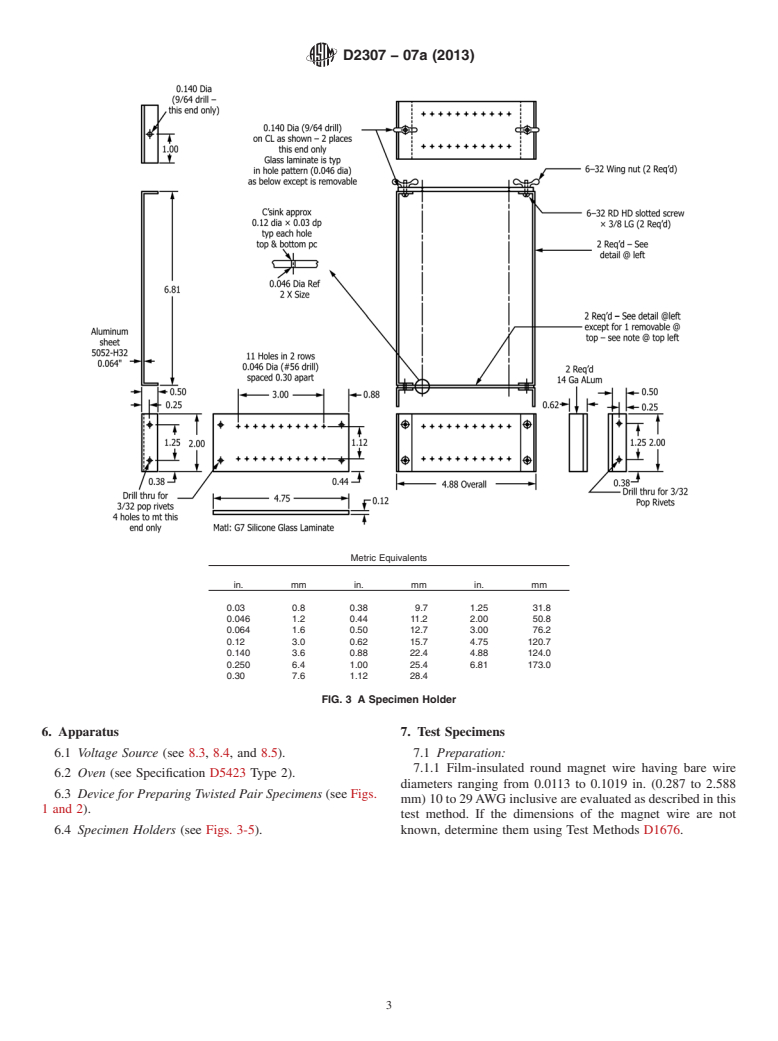
FIG. 3 A Specimen Holder
6. Apparatus 7. Test Specimens
6.1 Voltage Source (see 8.3, 8.4, and 8.5). 7.1 Preparation:
7.1.1 Film-insulated round magnet wire having bare wire
6.2 Oven (see Specification D5423 Type 2).
diameters ranging from 0.0113 to 0.1019 in. (0.287 to 2.588
6.3 Device for Preparing Twisted Pair Specimens (see Figs.
mm) 10 to 29AWG inclusive are evaluated as described in this
1 and 2).
test method. If the dimensions of the magnet wire are not
6.4 Specimen Holders (see Figs. 3-5). known, determine them using Test Methods D1676.
D2307 − 07a (2013)
7.2 Number of Test Specimens—The accuracy of the test
results depends largely upon the number of test specimens
exposed at each temperature. A greater number of test speci-
mens is required to achieve an acceptable degree of accuracy if
there is a wide spread in results among the specimens exposed
at each temperature. Use a minimum of 10 specimens for each
temperature. It is permissible to evaluate a greater number of
specimens if desired.
7.3 Specimen Holder—It has been found that individual
handling of the twisted specimens will introduce premature
failures. It is, therefore, mandatory that the specimens be
placed in a suitable holder. Design the holder in a manner that
will protect the twisted specimens from external mechanical
damageandwarpage.Anexampleofasuitableholderisshown
in Figs. 3 and 4. Construct the holder so as to allow for the
electricalconnectionofthetwistsfortheprooftesting(seeFig.
5 for an example).
7.4 Electrical Connection—Provide a suitable electrical
connection to the test specimens in the holder that will not
induce mechanical stress to the specimens. Non-mechanical
connections are preferred. A typical device is shown in Fig. 5.
FIG. 4 A Specimen Holder
The specimens are connected to a voltage source as described
in 8.3 and 8.4.
8. Procedure
8.1 Priortothefirstexposurecycle,makesureallspecimens
pass the proof-voltage test (see Table 2). Expose the specimens
at elevated temperatures in accordance with Table 3. Remove
the specimens from the oven and cool to room temperature
before testing. Test by applying the voltage specified in Table
2. Take care to prevent damage to the specimens.
8.2 Exposure Times—The exposure times given in Table 3
are selected to subject the test specimen to approximately ten
cycles before all specimens fail. It is permissible to extend
Table 3 at the high end of the exposure temperature range to
accommodate special high-temperature film insulations. The
thermal endpoint time of the specimens will possibly be
affected by the number of cycles. Log average or median hour
values, obtained from test specimens subjected to less than
eight cycles or more than twenty cycles at the exposure
temperature are possibly unreliable. Therefore, to ensure the
number of cycles to failure will be within the parameters,
adjust the exposure time. For example, if a set of test
specimens has been exposed for eight cycles and less than half
have failed, it is recommended that the exposure time should
be approximately doubled, and if the test shows a 30 % or
greater failure rate by the fourth cycle, it is recommended that
FIG. 5 A Specimen Holder and Electrical Connection Device
the exposure time should be reduced by one-half. Expose test
specimens to at least three temperatures. It is recommended
7.1.2 Form a length of wire approximately 16 in. (400 mm) that exposure temperatures be at least 10°C apart. Select the
long into a U shape and twist together for a distance of 4.75 6 lowest test temperature to be no more than 20°C above the
0.25 in. (120 6 6 mm) with a device similar to those shown in estimated temperature index of the magnet wire. Space the test
Figs.1and2.Thewindingweightappliedtothewirespecimen temperatures equally so that they cover a range of at least
while being twisted and the number of twists (full 360° 40°C. The accuracy of the time to failure predicted from the
rotations of the head of the twist maker) are given in Table 1. results will increase as the exposure temperature approaches
7.1.3 If specimens are to evaluated with a varnish, see Test the temperature to which the insulation is exposed in service.
Method D3251. The end point at the lowest exposure temperature must be at
D2307 − 07a (2013)
NOTE 1—This graph should contain all appropriate information regarding the insulating materials.
FIG. 6 Example of a Regression Line Plot (Table 5)
TABLE 1 Tension and Number of Twists for Twisted Pair Construction
Nominal Bare Wire Diameter Winding Weight on Specimens (± 2%)
Wire Size Total
A
AWG Twists
in. mm kg lb
0.102 to 0.091 2.59 to 2.30 10 to 11 3 10.8 24
0.081 to 0.064 2.05 to 1.63 12 to 14 4 5.4 12
0.057 to 0.045 1.45 to 1.15 15 to 17 6 2.7 6
0.040 to 0.032 1.02 to 0.81 18 to 20 8 1.35 3
B
0.029 to 0.023 0.72 to 0.57 21 to 23 12 0.70 1.5
0.020 to 0.016 0.51 to 0.40 24 to 26 16 0.34 .
0.014 to 0.011 0.36 to 0.29 27 to 29 20 0.17 .
A
Prepare test specimens, of intermediate diameters, in accordance with the requirements for the next smaller AWG size.
B
For weights less than 1.5 lb, use kilogram weights.
D2307 − 07a (2013)
TABLE 2 Proof-Voltage Test
9. Failure Time Calculations
Difference Between the Bare Wire
AC Test
A 9.1 Specimen Failure Time—The specimen failure time is
and Insulated Wire Diameters
Voltage, V
the sum of the total hours at the time of failure minus one-half
±5%
in. mm
the hours of the last cycle. As an example, suppose a given
0.0015 to 0.0020 0.036 to 0.050 500
0.0021 to 0.0027
...
Questions, Comments and Discussion
Ask us and Technical Secretary will try to provide an answer. You can facilitate discussion about the standard in here.