


ASTM F2702-08
(Test Method)Standard Test Method for Radiant Heat Performance of Flame Resistant Clothing Materials with Burn Injury Prediction
Standard Test Method for Radiant Heat Performance of Flame Resistant Clothing Materials with Burn Injury Prediction
SIGNIFICANCE AND USE
This test method is intended for the determination of the radiant heat performance value of a material, a combination of materials, or a comparison of different materials used in flame resistant clothing for workers exposed to radiant thermal hazards.
This test method evaluates a material’s heat transfer properties when exposed to a heat exposure at a constant value and systematically varied durations. Air movement at the face of the specimen and around the calorimeter can affect the measured heat transferred due to forced convective heat losses. Minimizing air movement around the specimen and test apparatus will aid in the repeatability of the results.
This test method accounts for the thermal energy contained in the exposed test specimen after the radiant heat exposure has ceased. Higher values of Radiant Heat Performance rating determined in this test associate to higher values of radiant energy protection against a predicted skin burn injury.
This test method maintains the specimen in a static, vertical position and does not involve movement except that resulting from the exposure procedure.
This test method specifies two standard sets of exposure conditions, 21 kW/m2 (0.5 cal/cm2s) and 84 kW/m2 (2.0 cal/cm2s). Either can be used.
5.5.1 If a different set of exposure conditions is used, it is likely that different results will be obtained.
5.5.2 The optional use of other conditions representative of the expected hazard, in addition to the standard set of exposure conditions, is permitted. However, the exposure conditions used must be reported with the results along with a determination of the exposure energy level stability.
SCOPE
1.1 This test method measures thermal protective characteristics of flame resistant textile materials subjected to a standardized radiant heat exposure relative to a predicted second-degree skin burn injury.
1.1.1 This test method is not applicable to textile materials that are not flame resistant.
Note 1—The determination of a textile material’s flame resistance shall be made prior to testing and done according to the applicable performance and/or specification standard for the textile material’s end-use.
1.1.2 This test method accounts for the thermal energy contained in an exposed test specimen after the standardized radiant heat exposure has ceased.
1.2 This test method is used to measure and describe the response of materials, products, or assemblies to heat under controlled conditions, but does not by itself incorporate all factors required for fire hazard or fire risk assessment of the materials, products, or assemblies under actual fire conditions.
1.3 The values stated in SI units are to be regarded as standard. The values given in parentheses are mathematical conversions to inch-pound or other units that are commonly used for thermal testing.
1.4 This standard does not purport to address the safety concerns, if any, associated with its use. It is the responsibility of the user of this standard to establish appropriate safety and health practices and determine the applicability of regulatory limitations prior to use.
General Information
Standards Content (Sample)
NOTICE: This standard has either been superseded and replaced by a new version or withdrawn.
Contact ASTM International (www.astm.org) for the latest information
Designation:F2702 −08
StandardTest Method for
Radiant Heat Performance of Flame Resistant Clothing
Materials with Burn Injury Prediction
This standard is issued under the fixed designation F2702; the number immediately following the designation indicates the year of
original adoption or, in the case of revision, the year of last revision.Anumber in parentheses indicates the year of last reapproval.A
superscript epsilon (´) indicates an editorial change since the last revision or reapproval.
1. Scope D1777Test Method for Thickness of Textile Materials
D3776Test Methods for Mass Per Unit Area (Weight) of
1.1 This test method measures thermal protective character-
Fabric
istics of flame resistant textile materials subjected to a stan-
D4157Test Method for Abrasion Resistance of Textile
dardized radiant heat exposure relative to a predicted second-
Fabrics (Oscillatory Cylinder Method)
degree skin burn injury.
E457Test Method for Measuring Heat-Transfer Rate Using
1.1.1 This test method is not applicable to textile materials
a Thermal Capacitance (Slug) Calorimeter
that are not flame resistant.
F1494Terminology Relating to Protective Clothing
NOTE1—Thedeterminationofatextilematerial’sflameresistanceshall
2.2 Other Standards:
bemadepriortotestinganddoneaccordingtotheapplicableperformance
CCC-C-419 Federal Specification for Cloth, Duck,
and/or specification standard for the textile material’s end-use.
Unbleached, Plied-Yarns, Army and Numbered
1.1.2 This test method accounts for the thermal energy
contained in an exposed test specimen after the standardized
3. Terminology
radiant heat exposure has ceased.
3.1 Definitions:
1.2 This test method is used to measure and describe the
3.1.1 break-open, n—in testing thermal protective
response of materials, products, or assemblies to heat under
materials, a material response evidenced by the formation of a
controlled conditions, but does not by itself incorporate all
holeinthetestspecimenduringthethermalexposurethatmay
factors required for fire hazard or fire risk assessment of the
result in the exposure energy in direct contact with the heat
materials, products, or assemblies under actual fire conditions.
sensor.
1.3 The values stated in SI units are to be regarded as
3.1.1.1 Discussion—The specimen is considered to exhibit
standard. The values given in parentheses are mathematical
breakopen when a hole is produced as a result of the thermal
conversions to inch-pound or other units that are commonly
2 2
exposurethatisatleast3.2cm (0.5in. )inareaoratleast2.5
used for thermal testing.
cm (1.0 in.) in any dimension. Single threads across the
1.4 This standard does not purport to address the safety
opening or hole do not reduce the size of the hole for the
concerns, if any, associated with its use. It is the responsibility
purposes of this test method.
of the user of this standard to establish appropriate safety and
3.1.2 charring, n—the formation of a carbonaceous residue
health practices and determine the applicability of regulatory
as the result of pyrolysis or incomplete combustion.
limitations prior to use.
3.1.3 dripping,n—amaterialresponseevidencedbyflowing
of the polymer.
2. Referenced Documents
3.1.4 embrittlement, n—the formation of a brittle residue as
2.1 ASTM Standards:
a result of pyrolysis or incomplete combustion.
D123Terminology Relating to Textiles
D1776Practice for Conditioning and Testing Textiles
3.1.5 heat flux, n—the thermal intensity indicated by the
amountofenergytransmitteddividedbyareaandtime;kW/m
(cal/cm ·s).
ThistestmethodisunderthejurisdictionofASTMCommitteeF23onPersonal
3.1.6 ignition, n—the initiation of combustion.
ProtectiveClothingandEquipmentandisthedirectresponsibilityofSubcommittee
F23.80 on Flame and Thermal.
3.1.7 melting, n—a material response evidenced by soften-
Current edition approved July 1, 2008. Published August 2008. DOI: 10.1520/
ing of the polymer.
F2702-08.
For referenced ASTM standards, visit the ASTM website, www.astm.org, or
3.1.8 radiant heat performance (RHP), n—in testing of
contact ASTM Customer Service at service@astm.org. For Annual Book of ASTM
thermal protective materials, the cumulative amount of trans-
Standards volume information, refer to the standard’s Document Summary page on
the ASTM website. ferred energy identified by the intersection of a measured
Copyright © ASTM International, 100 Barr Harbor Drive, PO Box C700, West Conshohocken, PA 19428-2959. United States
F2702−08
time-dependent heat transfer response through a subject mate- 3.1.13.1 Discussion—the determination of a single radiant
rial to a time-dependent, empirical predicted second-degree heatperformanceestimatevaluerequiresexposinganumberof
skin burn injury performance curve , expressed as a rating or specimens under varying exposure conditions so that the
2 2
value; J/cm (cal/cm ). thermal energy left in the sample after the radiant source is
removed is considered and accounted for when determining
3.1.9 response to heat exposure, n—in testing of thermal
performance against a burn injury prediction.
protective materials, the observable response of the textile to
the energy exposure as indicated by break-open, melting,
3.1.14 For the definitions of protective clothing terms used
dripping, charring, embrittlement, shrinkage, sticking, and in this method, refer to Terminology F1494, and for other
ignition.
textile terms used in this method, refer to Terminology D123.
3.1.10 second-degree burn injury, n—in testing of thermal
4. Summary of Test Method
protective materials, reversible burn damage at the epidermis/
4.1 A vertically positioned test specimen is exposed to a
dermis interface in human tissue.
radiant heat source with an exposure heat flux of either (a) 21
3.1.11 shrinkage, n—a decrease in one or more dimensions 2 2 2 2
kW/m (0.5 cal/cm s) or (b) 84 kW/m (2 cal/cm s).
of an object or material.
NOTE 2—Other exposure heat flux values are allowed. The test facility
3.1.12 sticking, n—a material response evidenced by soft-
shall verify the stability of the exposure level over the material exposure
ening and adherence of the material to the surface of itself or
time interval (used to determine the radiant heat performance value) and
include this in the test results report.
another material.
4.2 The transfer of heat through the test specimen is
3.1.13 sample test suite, n—any number of test specimens
measured using a copper slug calorimeter. The change in
used to derive a single thermal performance estimate value.
temperatureversustimeisused,alongwiththeknownthermo-
physical properties of copper to determine the respective
thermal energy delivered.
4.3 ARadiant Heat Performance value of the test specimen
Derived from: Stoll,A.M. and Chianta, M.A., “Method and Rating System for
Evaluations of Thermal Protection”, Aerospace Medicine, Vol 40, 1969, pp. is determined iteratively as the intersection of the time-
1232-1238 and Stoll, A.M. and Chianta, M.A., “Heat Transfer through Fabrics as
dependentcumulativeradiantheatresponseasmeasuredbythe
Related toThermal Injury”,Transactions – NewYorkAcademy of Sciences,Vol 33
(7), Nov. 1971, pp. 649-670.
FIG. 1General Expanded View of a Compliant Radiant Heat Performance Test Apparatus (see Figs. 2-4 for specific item details)
F2702−08
calorimeter to a time-dependent, empirical predicted second- 5.5 Thistestmethodspecifiestwostandardsetsofexposure
2 2 2
degree skin burn injury performance curve identified in conditions, 21 kW/m (0.5 cal/cm s) and 84 kW/m (2.0
10.2.1.4. cal/cm s). Either can be used.
5.5.1 If a different set of exposure conditions is used, it is
4.4 Subjective observations of the thermal response of
likely that different results will be obtained.
tested specimens are optionally noted.
5.5.2 The optional use of other conditions representative of
theexpectedhazard,inadditiontothestandardsetofexposure
5. Significance and Use
conditions, is permitted. However, the exposure conditions
5.1 Thistestmethodisintendedforthedeterminationofthe
used must be reported with the results along with a determi-
radiant heat performance value of a material, a combination of
nation of the exposure energy level stability.
materials, or a comparison of different materials used in flame
6. Apparatus and Materials
resistant clothing for workers exposed to radiant thermal
hazards.
6.1 General Arrangement—The apparatus consists of a
vertically oriented radiant heat source, specimen holder
5.2 This test method evaluates a material’s heat transfer
assembly, protective shutter, sensor assembly, and data
propertieswhenexposedtoaheatexposureataconstantvalue
acquisition/analysis system. The general arrangement of the
and systematically varied durations.Air movement at the face
radiant heat source, specimen holder, and protective shutter of
of the specimen and around the calorimeter can affect the
a suitable apparatus is shown in Fig. 1.
measuredheattransferredduetoforcedconvectiveheatlosses.
6.1.1 Radiant Heat Source—A suitable, vertically oriented
Minimizing air movement around the specimen and test
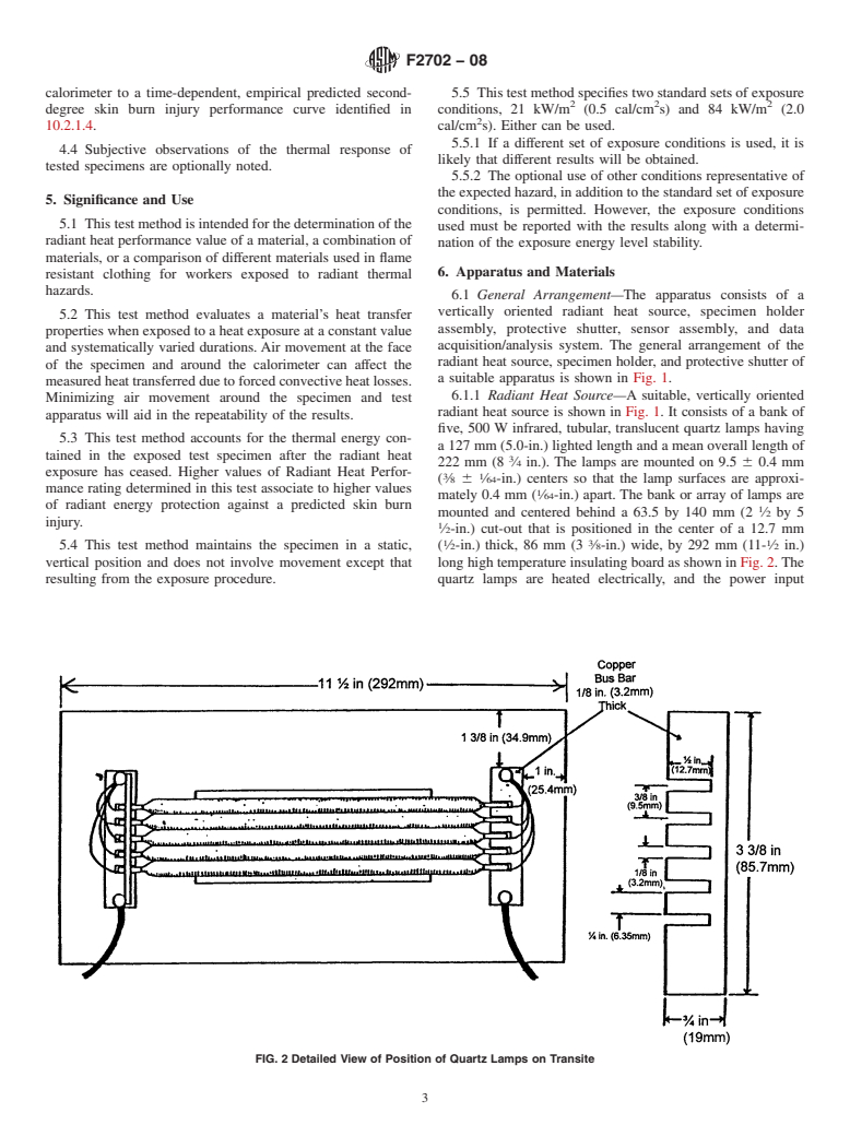
radiant heat source is shown in Fig. 1. It consists of a bank of
apparatus will aid in the repeatability of the results.
five, 500 W infrared, tubular, translucent quartz lamps having
5.3 This test method accounts for the thermal energy con-
a 127 mm (5.0-in.) lighted length and a mean overall length of
tained in the exposed test specimen after the radiant heat
222 mm (8 ⁄4 in.). The lamps are mounted on 9.5 6 0.4 mm
exposure has ceased. Higher values of Radiant Heat Perfor-
3 1
( ⁄8 6 ⁄64-in.) centers so that the lamp surfaces are approxi-
mance rating determined in this test associate to higher values
mately 0.4 mm ( ⁄64-in.) apart. The bank or array of lamps are
of radiant energy protection against a predicted skin burn
mounted and centered behind a 63.5 by 140 mm (2 ⁄2 by 5
injury.
⁄2-in.) cut-out that is positioned in the center of a 12.7 mm
1 3 1
( ⁄2-in.) thick, 86 mm (3 ⁄8-in.) wide, by 292 mm (11- ⁄2 in.)
5.4 This test method maintains the specimen in a static,
vertical position and does not involve movement except that longhightemperatureinsulatingboardasshowninFig.2.The
resulting from the exposure procedure. quartz lamps are heated electrically, and the power input
FIG. 2Detailed View of Position of Quartz Lamps on Transite
F2702−08
controlled by means of a rheostat or variable power supply coversthecompletecutoutsection(seetypicaldesignsinFigs.
having a capacity of at least 25A. 3 and 4). Several specimen holders are recommended to
6.1.1.1 Setting and monitoring the voltmeter readout on a facilitate testing.
voltage-controlled variable power supply is one method to
NOTE 6—The copper calorimeter sensor assembly holder plate bracket
calibrate and monitor the exposure level during the testing on
isconstructedsuchthatthecalorimeterassemblyisinareproduciblefixed
a system so equipped. A voltmeter, accurate to 6 1V, is
vertical position when installed and is held flush and rigidly against the
rear holder plate.
typically installed with the appropriate load circuit to indicate
lamp operating power.
6.1.3 Protective Shutter—A protective shutter, as shown in
6.1.1.2 Any covers or guards installed on the quartz lamp
Fig. 3, is placed between the radiant energy source and the
assembly shall be designed such that any convective energy
specimen.The protective shutter blocks the radiant energy just
generated is not allowed to impinge on the sample specimen
prior to the exposure of a specimen. Manual and mechanically
(vertical, unimpeded ventilation is required).
operated shutter designs are allowed with and without water-
cooling.
NOTE 3—Radiant measurement systems designed with closed lamp
6.1.4 Rheostat or Variable Power Supply—Astandard labo-
assembly covers and covers with minimal ventilation have been found to
exhibit large measurement biases in round robin testing.
ratory rheostat or appropriate power supply with a capacity of
NOTE 4—Quartz infrared lamps, part description QH500T3/CL from
at least 25Athat is capable of controlling the output intensity
General Electric Company, Consumer & Industrial Lighting Products and
of the radiant tubes over the range specified in 4.1.
part description 500T3, No. 21651-5 from Philips Lighting Co., Specialty
6.1.5 Sensor—The radiant heat sensor is a 40 6 0.5 mm
Lamps have been found to be effective.
NOTE 5—Transite monolithic, non-asbestos fiber cement board from diameter circular copper slug calorimeter constructed from
BNZ Materials, Inc. has been found to be effective as a high temperature
electrical grade copper with a mass of 18 6 0.05 grams (prior
insulating board.
todrilling)withasingleANSItypeJ(Fe/Cu-Ni)orANSItype
6.1.2 Specimen Holder Assembly—A specimen holder and K (Ni-Cr/Ni-Al) thermocouple wire bead (0.254 mm wire
holder plate with a 64 × 152 mm (2 ⁄2 × 6-in.) center cut-out
diameter or finer—equivalent to 30 AWG) installed as identi-
ispositionedsothatthedistancefromthenearestlampsurface fied in 6.1.5.2 and shown in Fig. 5. The sensor holder shall be
tothetestspecimenis25.4 60.4mm(1.0 6 ⁄64in.).Therear
constructed from non-conductive heat resistant material with a
holder plate thickness is 0.9 6 0.05 mm (0.036 6 0.002 in.)
and includes a bracket to hold the copper calorimeter sensor
assembly.This rear plate holds the specimen in place so that it See ASTM E457 for information regarding slug calorimeters.
FIG. 3Detailed View of a Typical Radiant Heat Performance Test Apparatus Showing Holder with Window, Shutter Plate, and Specimen
Holder with Calorimeter Brackets. A Magnet/Tab Arrangement is Shown as an Equipment Design Option to Hold the Specimen Holder
to the Assembly.
F2702−08
FIG. 4Sample Position Example—Top View Enlargement
NOTE 1—Secure the copper disk into the supporting insulation board with three sewing pins cut to a nominal 5 mm (0.375 in.) in length positioned
around the periphery so that the sewing pin heads hold the disk into the board.
FIG. 5Radiant Heat Performance test sensor (copper calorimeter mounted in insulation block) showing the mechanical bonding option
of thermocouple to copper disk
thermalconductivityvalueof≤0.15W/m•K,hightemperature absence of manufacturers instructions, an external heat source,
stability, and resistance to thermal shock. The board shall be forexample,anexternalheatlamp,shallbeusedtocompletely
nominally 1.3 cm (0.5 in.) or greater in thickness and meet the drive off any remaining organic carriers in a freshly painted
specimenholderassemblyrequirementsof6.1.2.Thesensoris surface before use.
held into the recess of the board using three s
...
Questions, Comments and Discussion
Ask us and Technical Secretary will try to provide an answer. You can facilitate discussion about the standard in here.