

ASTM A523/A523M-21
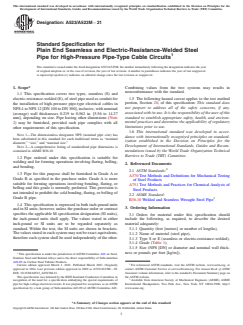
(Specification)Standard Specification for Plain End Seamless and Electric-Resistance-Welded Steel Pipe for High-Pressure Pipe-Type Cable Circuits
General Information
- Abstract
ABSTRACT
This specification covers seamless and electric-resistance-welded steel pipe used as conduit for the installation of high-pressure pipe-type electrical cables in NPS 4 to NPS 12, inclusive, with nominal (average) wall thicknesses 0.219 to 0.562 in., depending on size. The steel shall be made by one or more of the following processes: open-hearth, basic-oxygen, or electric-furnace. Tensile strength tests, flattening test, hydrostatic tests shall be made for the materials to conform the requirements as specified. If the results of the mechanical tests do not conform to requirements specified, retests shall be made.
SCOPE
1.1 This specification covers two types, seamless (S) and electric-resistance-welded (E), of steel pipe used as conduit for the installation of high-pressure pipe-type electrical cables in NPS 4 to NPS 12 [DN 100 to DN 300], inclusive, with nominal (average) wall thicknesses 0.219 to 0.562 in. [5.56 to 14.27 mm], depending on size. Pipe having other dimensions (Note 2) may be furnished, provided such pipe complies with all other requirements of this specification.
Note 1: The dimensionless designator NPS (nominal pipe size) has been substituted in this standard for such traditional terms as “nominal diameter,” “size,” and “nominal size.”
Note 2: A comprehensive listing of standardized pipe dimensions is contained in ASME B36.10.
1.2 Pipe ordered under this specification is suitable for welding and for forming operations involving flaring, belling, and bending.
1.3 Pipe for this purpose shall be furnished in Grade A or Grade B as specified in the purchase order. Grade A is more suitable for forming operations involving bending, flaring, or belling and this grade is normally preferred. This provision is not intended to prohibit the cold bending, flaring, or belling of Grade B pipe.
1.4 This specification is expressed in both inch-pound units and in SI units; however, unless the purchase order or contract specifies the applicable M specification designation (SI units), the inch-pound units shall apply. The values stated in either inch-pound or SI units are to be regarded separately as standard. Within the text, the SI units are shown in brackets. The values stated in each system may not be exact equivalents; therefore each system shall be used independently of the other. Combining values from the two systems may results in nonconformance with the standard.
1.5 The following hazard caveat applies to the test method portion, Section 20, of this specification: This standard does not purport to address all of the safety concerns, if any, associated with its use. It is the responsibility of the user of this standard to establish appropriate safety, health, and environmental practices and determine the applicability of regulatory limitations prior to use.
1.6 This international standard was developed in accordance with internationally recognized principles on standardization established in the Decision on Principles for the Development of International Standards, Guides and Recommendations issued by the World Trade Organization Technical Barriers to Trade (TBT) Committee.
- Status
- Published
- Publication Date
- 28-Feb-2021
- Technical Committee
- A01 - Steel, Stainless Steel and Related Alloys
- Drafting Committee
- A01.09 - Carbon Steel Tubular Products
Buy Documents
ASTM A523/A523M-21 - Standard Specification for Plain End Seamless and Electric-Resistance-Welded Steel Pipe for High-Pressure Pipe-Type Cable Circuits
REDLINE ASTM A523/A523M-21 - Standard Specification for Plain End Seamless and Electric-Resistance-Welded Steel Pipe for High-Pressure Pipe-Type Cable Circuits
Overview
ASTM A523/A523M-21 is the internationally recognized standard specification developed by ASTM International for plain end seamless and electric-resistance-welded steel pipe used as conduit in high-pressure pipe-type cable circuits. This standard is crucial for manufacturers, suppliers, and installers of steel pipe used in electrical infrastructure, specifically for housing high-pressure pipe-type electrical cables in nominal pipe sizes (NPS) 4 to 12 (DN 100 to DN 300) and wall thicknesses ranging from 0.219 to 0.562 inches (5.56 to 14.27 mm).
The specification details requirements for steel manufacturing processes, mechanical and chemical properties, testing protocols, permissible variations, and marking procedures-all designed to ensure quality, consistency, and suitability for demanding high-voltage electrical cable installations.
Key Topics
Product Types and Grades
- Covers two types: Seamless (S) and Electric-Resistance-Welded (E) steel pipe.
- Available in Grade A (preferred for forming operations such as bending, flaring, or belling) and Grade B.
Manufacturing Processes
- Steel must be produced by open-hearth, basic-oxygen, or electric-furnace methods.
- Pipes may be strand cast or cast in ingots.
Mechanical and Chemical Requirements
- Strict limits on chemical composition (carbon, manganese, phosphorus, sulfur).
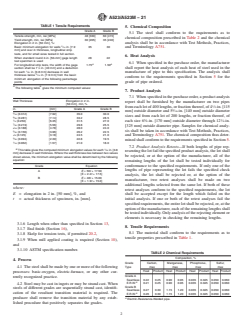
- Minimum tensile and yield strength requirements, as specified for each grade.
- Elongation requirements based on wall thickness.
Testing and Inspection
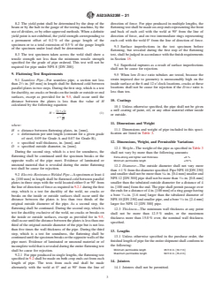
- Mandatory tensile, flattening, and hydrostatic pressure testing for each production lot and pipe length.
- Product analysis and retesting provisions to ensure conformance.
Dimensional Tolerances
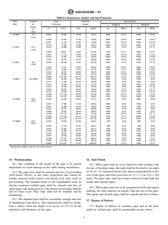
- Controls for outside diameter, wall thickness, and length.
- Smooth internal finish required to prevent cable damage during installation.
Identification and Marking
- Clear marking including manufacturer identity, pipe type, grade, dimensions, and the ASTM specification number.
- Optional bar coding is supported for enhanced traceability.
Applications
The pipes specified under ASTM A523/A523M-21 are designed specifically for use as conduits in high-pressure pipe-type cable circuits. Typical practical applications include:
- Underground and high-voltage power transmission systems requiring robust conduit for pressurized cable protection.
- Urban infrastructure where high reliability and safety for electric distribution is essential.
- Industrial facilities where stringent mechanical and chemical standards must be met for electrical cable protection.
Because these pipes must withstand high internal pressures and provide a defect-free, smooth bore for cable installation, compliance with this standard is critical for long-term reliability and operational safety.
Related Standards
In addition to ASTM A523/A523M-21, users may need to consult related standards for additional guidance or regulatory compliance, including:
- ASME B36.10 - Welded and seamless wrought steel pipe dimensions, referenced for comprehensive size listings.
- ASTM A370 - Test methods for mechanical testing of steel products.
- ASTM A751 - Practices for chemical analysis of steel products.
These documents provide complementary requirements and test methods, ensuring complete conformity in the procurement and application of steel pipe for electrical cable circuits.
By adhering to ASTM A523/A523M-21, manufacturers and infrastructure developers ensure their steel conduit systems conform to internationally recognized quality benchmarks, reducing risk, and supporting the reliable performance of high-pressure electrical transmission systems.
Relations
- Effective Date
- 01-Mar-2024
- Effective Date
- 01-Jul-2019
- Refers
ASTM A370-17a - Standard Test Methods and Definitions for Mechanical Testing of Steel Products - Effective Date
- 15-Nov-2017
- Effective Date
- 01-Jan-2017
- Effective Date
- 01-Nov-2015
- Effective Date
- 15-May-2014
- Effective Date
- 01-Mar-2014
- Effective Date
- 15-Nov-2013
- Refers
ASTM A370-12a - Standard Test Methods and Definitions for Mechanical Testing of Steel Products - Effective Date
- 15-Oct-2012
- Effective Date
- 15-Mar-2012
- Refers
ASTM A370-11a - Standard Test Methods and Definitions for Mechanical Testing of Steel Products - Effective Date
- 15-Nov-2011
- Effective Date
- 15-Jun-2010
- Refers
ASTM A370-09a - Standard Test Methods and Definitions for Mechanical Testing of Steel Products - Effective Date
- 01-Jun-2009
- Refers
ASTM A370-09ae1 - Standard Test Methods and Definitions for Mechanical Testing of Steel Products - Effective Date
- 01-Jun-2009
- Effective Date
- 01-Jan-2009
Buy Documents
ASTM A523/A523M-21 - Standard Specification for Plain End Seamless and Electric-Resistance-Welded Steel Pipe for High-Pressure Pipe-Type Cable Circuits
REDLINE ASTM A523/A523M-21 - Standard Specification for Plain End Seamless and Electric-Resistance-Welded Steel Pipe for High-Pressure Pipe-Type Cable Circuits
Get Certified
Connect with accredited certification bodies for this standard

Institut za varilstvo d.o.o. (Welding Institute)
Slovenia's leading welding institute since 1952. ISO 3834, EN 1090, pressure equipment certification, NDT personnel, welder qualification. Only IIW Au
Sponsored listings
Frequently Asked Questions
ASTM A523/A523M-21 is a technical specification published by ASTM International. Its full title is "Standard Specification for Plain End Seamless and Electric-Resistance-Welded Steel Pipe for High-Pressure Pipe-Type Cable Circuits". This standard covers: ABSTRACT This specification covers seamless and electric-resistance-welded steel pipe used as conduit for the installation of high-pressure pipe-type electrical cables in NPS 4 to NPS 12, inclusive, with nominal (average) wall thicknesses 0.219 to 0.562 in., depending on size. The steel shall be made by one or more of the following processes: open-hearth, basic-oxygen, or electric-furnace. Tensile strength tests, flattening test, hydrostatic tests shall be made for the materials to conform the requirements as specified. If the results of the mechanical tests do not conform to requirements specified, retests shall be made. SCOPE 1.1 This specification covers two types, seamless (S) and electric-resistance-welded (E), of steel pipe used as conduit for the installation of high-pressure pipe-type electrical cables in NPS 4 to NPS 12 [DN 100 to DN 300], inclusive, with nominal (average) wall thicknesses 0.219 to 0.562 in. [5.56 to 14.27 mm], depending on size. Pipe having other dimensions (Note 2) may be furnished, provided such pipe complies with all other requirements of this specification. Note 1: The dimensionless designator NPS (nominal pipe size) has been substituted in this standard for such traditional terms as “nominal diameter,” “size,” and “nominal size.” Note 2: A comprehensive listing of standardized pipe dimensions is contained in ASME B36.10. 1.2 Pipe ordered under this specification is suitable for welding and for forming operations involving flaring, belling, and bending. 1.3 Pipe for this purpose shall be furnished in Grade A or Grade B as specified in the purchase order. Grade A is more suitable for forming operations involving bending, flaring, or belling and this grade is normally preferred. This provision is not intended to prohibit the cold bending, flaring, or belling of Grade B pipe. 1.4 This specification is expressed in both inch-pound units and in SI units; however, unless the purchase order or contract specifies the applicable M specification designation (SI units), the inch-pound units shall apply. The values stated in either inch-pound or SI units are to be regarded separately as standard. Within the text, the SI units are shown in brackets. The values stated in each system may not be exact equivalents; therefore each system shall be used independently of the other. Combining values from the two systems may results in nonconformance with the standard. 1.5 The following hazard caveat applies to the test method portion, Section 20, of this specification: This standard does not purport to address all of the safety concerns, if any, associated with its use. It is the responsibility of the user of this standard to establish appropriate safety, health, and environmental practices and determine the applicability of regulatory limitations prior to use. 1.6 This international standard was developed in accordance with internationally recognized principles on standardization established in the Decision on Principles for the Development of International Standards, Guides and Recommendations issued by the World Trade Organization Technical Barriers to Trade (TBT) Committee.
ABSTRACT This specification covers seamless and electric-resistance-welded steel pipe used as conduit for the installation of high-pressure pipe-type electrical cables in NPS 4 to NPS 12, inclusive, with nominal (average) wall thicknesses 0.219 to 0.562 in., depending on size. The steel shall be made by one or more of the following processes: open-hearth, basic-oxygen, or electric-furnace. Tensile strength tests, flattening test, hydrostatic tests shall be made for the materials to conform the requirements as specified. If the results of the mechanical tests do not conform to requirements specified, retests shall be made. SCOPE 1.1 This specification covers two types, seamless (S) and electric-resistance-welded (E), of steel pipe used as conduit for the installation of high-pressure pipe-type electrical cables in NPS 4 to NPS 12 [DN 100 to DN 300], inclusive, with nominal (average) wall thicknesses 0.219 to 0.562 in. [5.56 to 14.27 mm], depending on size. Pipe having other dimensions (Note 2) may be furnished, provided such pipe complies with all other requirements of this specification. Note 1: The dimensionless designator NPS (nominal pipe size) has been substituted in this standard for such traditional terms as “nominal diameter,” “size,” and “nominal size.” Note 2: A comprehensive listing of standardized pipe dimensions is contained in ASME B36.10. 1.2 Pipe ordered under this specification is suitable for welding and for forming operations involving flaring, belling, and bending. 1.3 Pipe for this purpose shall be furnished in Grade A or Grade B as specified in the purchase order. Grade A is more suitable for forming operations involving bending, flaring, or belling and this grade is normally preferred. This provision is not intended to prohibit the cold bending, flaring, or belling of Grade B pipe. 1.4 This specification is expressed in both inch-pound units and in SI units; however, unless the purchase order or contract specifies the applicable M specification designation (SI units), the inch-pound units shall apply. The values stated in either inch-pound or SI units are to be regarded separately as standard. Within the text, the SI units are shown in brackets. The values stated in each system may not be exact equivalents; therefore each system shall be used independently of the other. Combining values from the two systems may results in nonconformance with the standard. 1.5 The following hazard caveat applies to the test method portion, Section 20, of this specification: This standard does not purport to address all of the safety concerns, if any, associated with its use. It is the responsibility of the user of this standard to establish appropriate safety, health, and environmental practices and determine the applicability of regulatory limitations prior to use. 1.6 This international standard was developed in accordance with internationally recognized principles on standardization established in the Decision on Principles for the Development of International Standards, Guides and Recommendations issued by the World Trade Organization Technical Barriers to Trade (TBT) Committee.
ASTM A523/A523M-21 is classified under the following ICS (International Classification for Standards) categories: 23.040.10 - Iron and steel pipes. The ICS classification helps identify the subject area and facilitates finding related standards.
ASTM A523/A523M-21 has the following relationships with other standards: It is inter standard links to ASTM A370-24, ASTM A370-19, ASTM A370-17a, ASTM A370-17, ASTM A370-15, ASTM A370-14, ASTM A751-14, ASTM A370-13, ASTM A370-12a, ASTM A370-12, ASTM A370-11a, ASTM A370-10, ASTM A370-09a, ASTM A370-09ae1, ASTM A370-09. Understanding these relationships helps ensure you are using the most current and applicable version of the standard.
ASTM A523/A523M-21 is available in PDF format for immediate download after purchase. The document can be added to your cart and obtained through the secure checkout process. Digital delivery ensures instant access to the complete standard document.
Standards Content (Sample)
This international standard was developed in accordance with internationally recognized principles on standardization established in the Decision on Principles for the
Development of International Standards, Guides and Recommendations issued by the World Trade Organization Technical Barriers to Trade (TBT) Committee.
Designation:A523/A523M −21
Standard Specification for
Plain End Seamless and Electric-Resistance-Welded Steel
Pipe for High-Pressure Pipe-Type Cable Circuits
This standard is issued under the fixed designationA523/A523M; the number immediately following the designation indicates the year
of original adoption or, in the case of revision, the year of last revision.Anumber in parentheses indicates the year of last reapproval.
A superscript epsilon (´) indicates an editorial change since the last revision or reapproval.
1. Scope* Combining values from the two systems may results in
nonconformance with the standard.
1.1 This specification covers two types, seamless (S) and
1.5 The following hazard caveat applies to the test method
electric-resistance-welded(E),ofsteelpipeusedasconduitfor
portion, Section 20, of this specification: This standard does
the installation of high-pressure pipe-type electrical cables in
not purport to address all of the safety concerns, if any,
NPS4toNPS12[DN100toDN300],inclusive,withnominal
associatedwithitsuse.Itistheresponsibilityoftheuserofthis
(average) wall thicknesses 0.219 to 0.562 in. [5.56 to 14.27
standard to establish appropriate safety, health, and environ-
mm], depending on size. Pipe having other dimensions (Note
mental practices and determine the applicability of regulatory
2) may be furnished, provided such pipe complies with all
limitations prior to use.
other requirements of this specification.
1.6 This international standard was developed in accor-
NOTE 1—The dimensionless designator NPS (nominal pipe size) has
dance with internationally recognized principles on standard-
been substituted in this standard for such traditional terms as “nominal
ization established in the Decision on Principles for the
diameter,” “size,” and “nominal size.”
Development of International Standards, Guides and Recom-
NOTE 2—A comprehensive listing of standardized pipe dimensions is
mendations issued by the World Trade Organization Technical
contained in ASME B36.10.
Barriers to Trade (TBT) Committee.
1.2 Pipe ordered under this specification is suitable for
welding and for forming operations involving flaring, belling,
2. Referenced Documents
and bending.
2.1 ASTM Standards:
1.3 Pipe for this purpose shall be furnished in Grade A or
A370Test Methods and Definitions for Mechanical Testing
Grade B as specified in the purchase order. Grade A is more
of Steel Products
suitable for forming operations involving bending, flaring, or
A751Test Methods and Practices for Chemical Analysis of
belling and this grade is normally preferred. This provision is
Steel Products
not intended to prohibit the cold bending, flaring, or belling of
2.2 ASME Standard:
Grade B pipe. 3
B36.10Welded and Seamless Wrought Steel Pipe
1.4 This specification is expressed in both inch-pound units
3. Ordering Information
and in SI units; however, unless the purchase order or contract
specifies the applicable M specification designation (SI units),
3.1 Orders for material under this specification should
the inch-pound units shall apply. The values stated in either
include the following, as required, to describe the desired
inch-pound or SI units are to be regarded separately as
material adequately:
standard. Within the text, the SI units are shown in brackets.
3.1.1 Quantity (feet [meters] or number of lengths),
Thevaluesstatedineachsystemmaynotbeexactequivalents;
3.1.2 Name of material (steel pipe),
therefore each system shall be used independently of the other.
3.1.3 Type S or E (seamless or electric-resistance-welded),
3.1.4 Grade (Table 1),
3.1.5 Size (NPS [DN] or diameter and nominal wall thick-
ness or pounds per foot [kg/m]),
This specification is under the jurisdiction ofASTM Committee A01 on Steel,
Stainless Steel and RelatedAlloys and is the direct responsibility of Subcommittee
A01.09 on Carbon Steel Tubular Products.
Current edition approved March 1, 2021. Published March 2021. Originally For referenced ASTM standards, visit the ASTM website, www.astm.org, or
approved in 1964. Last previous edition approved in 2020 as A523/A523M–20. contact ASTM Customer Service at service@astm.org. For Annual Book of ASTM
DOI: 10.1520/A0523_A0523M-21. Standards volume information, refer to the standard’s Document Summary page on
This specification was initiated by the IEEE Insulated Conductors Committee in the ASTM website.
recognition of the need for a specification embodying the special requirements of Available from American Society of Mechanical Engineers (ASME), ASME
pipeforhigh-voltageelectricalcircuits.ItwaspreparedforacceptanceasanASTM International Headquarters, Two Park Ave., New York, NY 10016-5990, http://
specification by a task group of Subcommittee A01.09 of ASTM Committee A01. www.asme.org.
*A Summary of Changes section appears at the end of this standard
Copyright © ASTM International, 100 Barr Harbor Drive, PO Box C700, West Conshohocken, PA 19428-2959. United States
A523/A523M−21
TABLE 1 Tensile Requirements
5. Chemical Composition
Grade A Grade B
5.1 The steel shall conform to the requirements as to
Tensile strength, min, ksi [MPa] 48 [330] 60 [415]
chemical composition prescribed in Table 2 and the chemical
Yield strength, min, ksi [MPa] 30 [205] 35 [240]
analysis shall be in accordance with Test Methods, Practices,
Elongation in 2 in. [50 mm], %:
Basic minimum elongation for walls ⁄16 in. [7.9 35 30
and Terminology A751.
mm] and over in thickness, longitudinal strip
tests, and for small sizes tested in full section.
6. Heat Analysis
When standard round 2-in. [50-mm] gage length 28 22
test specimen is used
6.1 When specified in the purchase order, the manufacturer
A A
For longitudinal strip tests, the width of the gage 1.75 1.50
shall report the heat analysis of each heat of steel used in the
section shall be 1 ⁄2 in. [40 mm] and a deduction
for each ⁄32 in. [0.8 mm] decrease in wall
manufacture of pipe to this specification. The analysis shall
thickness below ⁄16 in. [7.9 mm] from the basic
conform to the requirements specified in Section 5 for the
minimum elongation of the following percentage
grade of pipe ordered.
points
A B
The following table gives the minimum computed values:
7. Product Analysis
7.1 Whenspecifiedinthepurchaseorder,aproductanalysis
Wall Thickness Elongation in 2 in.
report shall be furnished by the manufacturer on two pipes
[50 mm], min, %
fromeachlotof400lengths,orfractionthereof,of4 ⁄2-in.[115
in. [mm] Grade A Grade B
mm] outside diameter and 5 ⁄16-in. [140 mm] outside diameter
⁄16 (0.312) [7.92] 35.0 30.0
sizes and from each lot of 200 lengths, or fraction thereof, of
⁄32 (0.281) [7.14] 33.2 28.5
5 3
⁄4 (0.250) [6.35] 31.5 27.0 each size 6 ⁄8-in. [170 mm] outside diameter through 12 ⁄4-in.
⁄32 (0.219) [5.56] 29.8 25.5
[325 mm] outside diameter pipe. Samples for chemical analy-
⁄16 (0.188) [4.78] 28.0 24.0
sis shall be taken in accordance with Test Methods, Practices,
⁄32 (0.156) [3.96] 26.2 22.5
⁄8 (0.125) [3.18] 24.5 21.0 and Terminology A751. The chemical composition thus deter-
⁄32 (0.094) [2.39] 22.8 19.5
minedshallconformtotherequirementsspecifiedinSection5.
⁄16 (0.062) [1.57] 21.0 18.0
7.2 Product Analysis Retests—If both lengths of pipe rep-
B
This table gives the computed minimum elongation values for each ⁄32 in. [0.8
resentingthelotfailthespecifiedproductanalysis,thelotshall
mm] decrease in wall thickness. Where the wall thickness lies between two values
be rejected, or at the option of the manufacturer, all of the
shown above, the minimum elongation value shall be determined by the following
equation:
remaining lengths of the lot shall be tested individually for
conformance to the specified requirements. If only one of the
Grade Equation
lengths of pipe representing the lot fails the specified check
A E=56t + 17.50
[E=2.2t + 17.5]
analysis, the lot shall be rejected or, at the option of the
B E=48t + 15.00
manufacturer, two retest analyses shall be made on two
[E=1.9t + 15.0]
additional lengths selected from the same lot. If both of these
where:
retest analyses conform to the specified requirements, the lot
E = elongation in 2 in. [50 mm],%, and shall be accepted except for the length which failed on the
t = actual thickness of specimen, in. [mm].
initial analysis. If one or both of the retest analyses fail the
specifiedrequirements,theentirelotshallberejected,or,atthe
option of the manufacturer, each of the remaining lengths shall
betestedindividually.Onlyanalysisoftherejectingelementor
elements is necessary in checking the remaining lengths.
3.1.6 Length when other than specified in Section 13,
8. Tensile Requirements
3.1.7 End finish (Section 16),
8.1 The material shall conform to the requirements as to
3.1.8 Skelp for tension tests, if permitted 20.2,
tensile properties prescribed in Table 1.
3.1.9 When mill applied coating is required (Section 10),
and
3.1.10 ASTM specification number.
TABLE 2 Chemical Requirements
Composition, %
4. Process
Grade Carbon, Manganese, Phosphorus, Sulfur,
Type max max max max
4.1 The steel shall be made by one or more of the following
Heat Product Heat Product Heat Product Heat Product
processes: basic-oxygen, electric-furnace, or any other cur-
Grade A
rently recognized practice.
Seamless 0.22 0.25 0.90 0.95 0.035 0.045 0.050 0.060
A
E.R.W. 0.21 0.25 0.90 0.95 0.035 0.045 0.050 0.060
4.2 Steel may be cast in ingots or may be strand cast.When
Grade B
steels of different grades are sequentially strand cast, identifi-
Seamless 0.27 0.30 1.15 1.20 0.035 0.045 0.050 0.060
A
cation of the resultant transition material is required. The
E.R.W. 0.26 0.30 1.15 1.20 0.035 0.045 0.050 0.060
producer shall remove the transition material by any estab- A
Electric-Resistance-Welded pipe.
lished procedure that positively separates the grades.
A523/A523M−21
8.2 The yield point shall be determined by the drop of the direction of force. For pipe produced in multiple lengths, the
beam or by the halt in the gauge of the testing machine, by the flatteningtestshallbemadeoncropendsrepresentingthefront
useofdividers,orbyotherapprovedmethods.Whenadefinite and back of each coil with the weld at 90° from the line of
yieldpointisnotexhibited,theyieldstrengthcorrespondingto direction of force, and on two intermediate rings representing
a permanent offset of 0.2% of the gauge length of the each coil with the weld 0° from the line of direction of force.
specimen or to a total extension of 0.5% of the gauge length
9.3 Surface imperfections in the test specimen before
of the specimen under load shall be determined.
flattening, but revealed during the first step of the flattening
8.3 The test specimen taken across the weld shall show a test,shallbejudgedinaccordancewiththefinishrequirements
tensile strength not less than the minimum tensile strength
in Section 15.
specified for the grade of pipe ordered. This test will not be
9.4 Superficial ruptures as a result of surface imperfections
required for pipe under NPS 8 [DN 200].
shall not be cause for rejection.
9. Flattening Test Requirements
9.5 When low D-to-t ratio tubulars are tested, because the
strain imposed due to geometry is unreasonably high on the
9.1 Seamless Pipe—For seamless pipe, a section not less
inside surface at the 6 and 12 o’clock locations, cracks at these
than 2 ⁄2 in. [65 mm] in length shall be flattened cold between
locations shall not be cause for rejection if the D-to-t ratio is
parallelplatesintwosteps.Duringthefirststep,whichisatest
less than ten.
forductility,nocracksorbreaksontheinsideoroutsideorend
surfaces, except as provided for in 9.5, shall occur until the
10. Coatings
distance between the plates is less than the value of H
calculated by the following equation:
10.1 Unless otherwise specified, the pipe shall not be given
11e t a mill coating of paint, oil, or any other material either inside
~ !
H 5 (1)
or outside.
t
e1
D
11. Dimensions and Weight
where:
11.1 Dimensions and weight of pipe included in this speci-
H = distance between flattening plates, in. [mm],
fication are listed in Table 3.
e = deformation per unit length (constant for a given grade
of steel, 0.09 for Grade A and 0.07 for Grade B),
12. Dimensions, Weight, and Permissible Variations
t = specified wall thickness, in. [mm], and
D = specified outside diameter, in. [mm].
12.1 Weight—The weight of the pipe as specified in Table 3
During the second step, which is a test for soundness, the
shall not vary by more than the following amounts:
flattening shall be continued until the specimen breaks or the
Extra-strong and lighter wall thickness ±5 %
opposite walls of the pipe meet. Evidence of laminated or Minimum permissible length ±10 %
unsound material that is revealed during the entire flattening
12.2 Diameter—The outside diameter shall not vary more
test shall be cause for rejection.
than 61%fromthediameterspecified.PipeNPS10[DN250]
andsmallershallnotbemorethan ⁄64in.[0.4mm]smallerand
9.2 Electric-Resistance-Welded Pipe—Aspecimenatleast4
NPS12[DN300]pipeshallnotbemorethan ⁄32-in.[0.8-mm]
in. [100 mm] in length shall be flattened cold between parallel
smaller than the tabulated outside diameter for a distance of 4
plates in three steps with the weld located either 0 or 90° from
in. [100 mm] from the end.The pipe shall permit passage over
thelineofdirectionofforceasrequiredin9.2.1duringthefirst
theendsforadistanceof4in.[100mm]ofaringgaugehaving
step, which is a test for ductility of the weld, no cracks or
a bore ⁄16-in. [1.6 mm] larger than the tabulated diameter of
breaks on the inside or outside surfaces shall occur until the
...
This document is not an ASTM standard and is intended only to provide the user of an ASTM standard an indication of what changes have been made to the previous version. Because
it may not be technically possible to adequately depict all changes accurately, ASTM recommends that users consult prior editions as appropriate. In all cases only the current version
of the standard as published by ASTM is to be considered the official document.
Designation: A523/A523M − 20 A523/A523M − 21
Standard Specification for
Plain End Seamless and Electric-Resistance-Welded Steel
Pipe for High-Pressure Pipe-Type Cable Circuits
This standard is issued under the fixed designation A523/A523M; the number immediately following the designation indicates the year
of original adoption or, in the case of revision, the year of last revision. A number in parentheses indicates the year of last reapproval.
A superscript epsilon (´) indicates an editorial change since the last revision or reapproval.
1. Scope*
1.1 This specification covers two types, seamless (S) and electric-resistance-welded (E), of steel pipe used as conduit for the
installation of high-pressure pipe-type electrical cables in NPS 4 to NPS 12 [DN 100 to DN 300], inclusive, with nominal (average)
wall thicknesses 0.219 to 0.562 in. [5.56 to 14.27 mm], depending on size. Pipe having other dimensions (Note 2) may be
furnished, provided such pipe complies with all other requirements of this specification.
NOTE 1—The dimensionless designator NPS (nominal pipe size) has been substituted in this standard for such traditional terms as “nominal diameter,”
“size,” and “nominal size.”
NOTE 2—A comprehensive listing of standardized pipe dimensions is contained in ASME B36.10.
1.2 Pipe ordered under this specification is suitable for welding and for forming operations involving flaring, belling, and bending.
1.3 Pipe for this purpose shall be furnished in Grade A or Grade B as specified in the purchase order. Grade A is more suitable
for forming operations involving bending, flaring, or belling and this grade is normally preferred. This provision is not intended
to prohibit the cold bending, flaring, or belling of Grade B pipe.
1.4 This specification is expressed in both inch-pound units and in SI units; however, unless the purchase order or contract
specifies the applicable M specification designation (SI units), the inch-pound units shall apply. The values stated in either
inch-pound or SI units are to be regarded separately as standard. Within the text, the SI units are shown in brackets. The values
stated in each system may not be exact equivalents; therefore each system shall be used independently of the other. Combining
values from the two systems may results in nonconformance with the standard.
1.5 The following hazard caveat applies to the test method portion, Section 20, of this specification: This standard does not
purport to address all of the safety concerns, if any, associated with its use. It is the responsibility of the user of this standard to
establish appropriate safety, health, and environmental practices and determine the applicability of regulatory limitations prior
to use.
1.6 This international standard was developed in accordance with internationally recognized principles on standardization
established in the Decision on Principles for the Development of International Standards, Guides and Recommendations issued
by the World Trade Organization Technical Barriers to Trade (TBT) Committee.
This specification is under the jurisdiction of ASTM Committee A01 on Steel, Stainless Steel and Related Alloys and is the direct responsibility of Subcommittee A01.09
on Carbon Steel Tubular Products.
Current edition approved March 1, 2020March 1, 2021. Published March 2020March 2021. Originally approved in 1964. Last previous edition approved in 20122020 as
A523 – 96 (2012).A523/A523M – 20. DOI: 10.1520/A0523_A0523M-20.10.1520/A0523_A0523M-21.
This specification was initiated by the IEEE Insulated Conductors Committee in recognition of the need for a specification embodying the special requirements of pipe
for high-voltage electrical circuits. It was prepared for acceptance as an ASTM specification by a task group of Subcommittee A01.09 of ASTM Committee A01.
*A Summary of Changes section appears at the end of this standard
Copyright © ASTM International, 100 Barr Harbor Drive, PO Box C700, West Conshohocken, PA 19428-2959. United States
A523/A523M − 21
2. Referenced Documents
2.1 ASTM Standards:
A370 Test Methods and Definitions for Mechanical Testing of Steel Products
A751 Test Methods and Practices for Chemical Analysis of Steel Products
2.2 ASME Standard:
B36.10 Welded and Seamless Wrought Steel Pipe
3. Ordering Information
3.1 Orders for material under this specification should include the following, as required, to describe the desired material
adequately:
3.1.1 Quantity (feet [meters] or number of lengths),
3.1.2 Name of material (steel pipe),
3.1.3 Type S or E (seamless or electric-resistance-welded),
3.1.4 Grade (Table 1),
3.1.5 Size (NPS [DN] or diameter and nominal wall thickness or pounds per foot [kg/m]),
3.1.6 Length when other than specified in Section 13,
3.1.7 End finish (Section 16),
3.1.8 Skelp for tension tests, if permitted 20.2,
3.1.9 When mill applied coating is required (Section 10), and
3.1.10 ASTM specification number.
4. Process
4.1 The steel shall be made by one or more of the following processes: basic-oxygen, electric-furnace, or any other currently
recognized practice.
4.2 Steel may be cast in ingots or may be strand cast. When steels of different grades are sequentially strand cast, identification
of the resultant transition material is required. The producer shall remove the transition material by any established procedure that
positively separates the grades.
5. Chemical Composition
5.1 The steel shall conform to the requirements as to chemical composition prescribed in Table 2 and the chemical analysis shall
be in accordance with Test Methods, Practices, and Terminology A751.
6. Heat Analysis
6.1 When specified in the purchase order, the manufacturer shall report the heat analysis of each heat of steel used in the
manufacture of pipe to this specification. The analysis shall conform to the requirements specified in Section 5 for the grade of
pipe ordered.
For referenced ASTM standards, visit the ASTM website, www.astm.org, or contact ASTM Customer Service at service@astm.org. For Annual Book of ASTM Standards
volume information, refer to the standard’s Document Summary page on the ASTM website.
Available from American Society of Mechanical Engineers (ASME), ASME International Headquarters, Two Park Ave., New York, NY 10016-5990, http://
www.asme.org.
A523/A523M − 21
TABLE 1 Tensile Requirements
Grade A Grade B
Tensile strength, min, ksi [MPa] 48 [330] 60 [415]
Yield strength, min, ksi [MPa] 30 [205] 35 [240]
Elongation in 2 in. or 50 mm, %:
Elongation in 2 in. [50 mm], %:
Basic minimum elongation for walls ⁄16 in. [7.9 35 30
mm] and over in thickness, longitudinal strip
tests, and for small sizes tested in full section.
When standard round 2-in. [50-mm] gage length 28 22
test specimen is used
A A
For longitudinal strip tests, the width of the gage 1.75 1.50
section shall be 1 ⁄2 in. [38.1 mm] and a
deduction for each ⁄32 in. [0.79 mm] decrease in
wall thickness below ⁄16 in. [7.94 mm] from the
basic minimum elongation of the following
percentage points
A A
For longitudinal strip tests, the width of the gage 1.75 1.50
section shall be 1 ⁄2 in. [40 mm] and a deduction
for each ⁄32 in. [0.8 mm] decrease in wall
thickness below ⁄16 in. [7.9 mm] from the basic
minimum elongation of the following percentage
points
A B
The following table gives the minimum computed values:
Wall Thickness Elongation in 2 in.
[50 mm], min, %
in. [mm] Grade A Grade B
⁄16 (0.312) [7.9] 35.0 30.0
⁄32 (0.281) [7.1] 33.2 28.5
⁄4 (0.250) [6.4] 31.5 27.0
⁄32 (0.219) [5.6] 29.8 25.5
⁄16 (0.188) [4.8] 28.0 24.0
⁄32 (0.156) [4.0] 26.2 22.5
⁄8 (0.125) [3.2] 24.5 21.0
⁄32 (0.094) [2.4] 22.8 19.5
⁄16 (0.062) [1.6] 21.0 18.0
Wall Thickness Elongation in 2 in.
[50 mm], min, %
in. [mm] Grade A Grade B
⁄16 (0.312) [7.92] 35.0 30.0
⁄32 (0.281) [7.14] 33.2 28.5
⁄4 (0.250) [6.35] 31.5 27.0
⁄32 (0.219) [5.56] 29.8 25.5
⁄16 (0.188) [4.78] 28.0 24.0
⁄32 (0.156) [3.96] 26.2 22.5
⁄8 (0.125) [3.18] 24.5 21.0
⁄32 (0.094) [2.39] 22.8 19.5
⁄16 (0.062) [1.57] 21.0 18.0
B
This table gives the computed minimum elongation values for each ⁄32 in.
[0.79[0.8 mm] decrease in wall thickness. Where the wall thickness lies between
two values shown above, the minimum elongation value shall be determined by
the following equation:
Grade Equation
A E = 56t + 17.50
[E = 2.2t + 17.5]
B E = 48t + 15.00
[E = 1.9t + 15.0]
where:
E = elongation in 2 in. [50 mm], %, and
t = actual thickness of specimen, in. [mm].
A523/A523M − 21
TABLE 2 Chemical Requirements
Composition, %
Grade Carbon, Manganese, Phosphorus, Sulfur,
Type max max max max
Heat Product Heat Product Heat Product Heat Product
Grade A
Seamless 0.22 0.25 0.90 0.95 0.035 0.045 0.050 0.060
A
E.R.W. 0.21 0.25 0.90 0.95 0.035 0.045 0.050 0.060
Grade B
Seamless 0.27 0.30 1.15 1.20 0.035 0.045 0.050 0.060
A
E.R.W. 0.26 0.30 1.15 1.20 0.035 0.045 0.050 0.060
A
Electric-Resistance-Welded pipe.
7. Product Analysis
7.1 When specified in the purchase order, a product analysis report shall be furnished by the manufacturer on two pipes from each
1 9
lot of 400 lengths, or fraction thereof, of 4 ⁄2-in. [115 mm] outside diameter and 5 ⁄16-in. [140 mm] outside diameter sizes and from
5 3
each lot of 200 lengths, or fraction thereof, of each size 6 ⁄8-in. [170 mm] outside diameter through 12 ⁄4-in. [325 mm] outside
diameter pipe. Samples for chemical analysis shall be taken in accordance with Test Methods, Practices, and Terminology A751.
The chemical composition thus determined shall conform to the requirements specified in Section 5.
7.2 Product Analysis Retests—If both lengths of pipe representing the lot fail the specified product analysis, the lot shall be
rejected, or at the option of the manufacturer, all of the remaining lengths of the lot shall be tested individually for conformance
to the specified requirements. If only one of the lengths of pipe representing the lot fails the specified check analysis, the lot shall
be rejected or, at the option of the manufacturer, two retest analyses shall be made on two additional lengths selected from the same
lot. If both of these retest analyses conform to the specified requirements, the lot shall be accepted except for the length which
failed on the initial analysis. If one or both of the retest analyses fail the specified requirements, the entire lot shall be rejected,
or, at the option of the manufacturer, each of the remaining lengths shall be tested individually. Only analysis of the rejecting
element or elements is necessary in checking the remaining lengths.
8. Tensile Requirements
8.1 The material shall conform to the requirements as to tensile properties prescribed in Table 1.
8.2 The yield point shall be determined by the drop of the beam or by the halt in the gauge of the testing machine, by the use of
dividers, or by other approved methods. When a definite yield point is not exhibited, the yield strength corresponding to a
permanent offset of 0.2 % of the gauge length of the specimen or to a total extension of 0.5 % of the gauge length of the specimen
under load shall be determined.
8.3 The test specimen taken across the weld shall show a tensile strength not less than the minimum tensile strength specified for
the grade of pipe ordered. This test will not be required for pipe under NPS 8 [DN 200].
9. Flattening Test Requirements
9.1 Seamless Pipe—For seamless pipe, a section not less than 2 ⁄2 in. [65 mm] in length shall be flattened cold between parallel
plates in two steps. During the first step, which is a test for ductility, no cracks or breaks on the inside or outside or end surfaces,
except as provided for in 9.5, shall occur until the distance between the plates is less than the value of H calculated by the following
equation:
~11e!t
H 5 (1)
t
e1
D
where:
H = distance between flattening plates, in. [mm],
e = deformation per unit length (constant for a given grade of steel, 0.09 for Grade A and 0.07 for Grade B),
t = specified wall thickness, in. [mm], and
A523/A523M − 21
D = specified outside diameter, in. [mm].
During the second step, which is a test for soundness, the flattening shall be continued until the specimen breaks or the opposite
walls of the pipe meet. Evidence of laminated or unsound material that is revealed during the entire flattening test shall be cause
for rejection.
9.2 Electric-Resistance-Welded Pipe—A specimen at least 4 in. [100 mm] in length shall be flattened cold between parallel plates
in three steps with the weld located either 0 or 90° from the line of direction of force as required in 9.2.1 during the first step, which
is a test for ductility of the weld, no cracks or breaks on the inside or outside surfaces shall occur until the distance between the
plates is less than two thirds of the original outside diameter of the pipe. As a second step, the flattening shall be continued. During
the second step, which is test for ductility exclusive of the weld, no cracks or breaks on the inside or outside surfaces, except as
provided for in 9.5, shall occur until the distance between the plates is less than one third of the original outside diameter of the
pipe but is not less than five times the wall thickness of the pipe. During the third step, which is a test for soundness, the flattening
shall be continued until the specimen breaks or the opposite walls of the pipe meet. Evidence of laminated or unsound material
or of incomplete weld that is revealed during the entire flattening test shall be cause for rejection.
9.2.1 For pipe produced in single lengths, the flattening test specified in 9.2 shall be made on both crop ends cut from each length
of pipe. The tests from each end shall be made alternately with the weld at 0° and at 90° from the line of direction of force. For
pipe produced in multiple lengths, the flattening test shall be made on crop ends representing the front and back of each coil with
the weld at 90° from the line of direction of force, and on two intermediate rings representing each coil with the weld 0° from the
line of direction of force.
9.3 Surface imperfections in the test specimen before
...