


ASTM E3168-20a
(Practice)Standard Practice for Determining Low-Contrast Visual Acuity of Radiographic Interpreters
Standard Practice for Determining Low-Contrast Visual Acuity of Radiographic Interpreters
SIGNIFICANCE AND USE
4.1 This practice is used to evaluate the ability of a radiographic interpreter to discriminate low contrast slit images in a radiographic interpretation environment. A radiographic viewer, as described in Specification E1390, and a viewing environment, as described in Guide E94, are strongly recommended. The minimum acceptable test score in any given application depends on the requirements of the application. Using parties should develop and maintain records of their test results to guide the establishment of acceptable test scores for their applications. (See Note 1.)
Note 1: During round robin testing with experienced radiographic interpreters, 76 % of the interpreters achieved a score of 85 % or higher, and 95 % achieved a score of 80 % or higher. The average score was 90.7 %, and the standard deviation was 6.7 %. In a second study from 2017, with both certified radiographers and uncertified personnel, the average and standard deviation among certified radiographers was 90.4 ± 4.0 % and among uncertified personnel was 88.4 ± 4.9 %. It was found that on each test page there are 3 or 4 images where the average score for each was less than 80 % correct and the remainder of the images all individually scored greater than 80 % on average. A limited number of the general public was examined, and the average score among these was 75.0 ± 3.3 %.
4.2 Administration of the Test
4.2.1 The test procedure described in this practice is intended to determine the ability of a radiographic interpreter to detect low contrast images in a low light level environment. Appropriate dark adaptation time should be permitted. A minimum of 1 min is recommended; however, longer dark adaptation times may be required by some users.
4.2.2 The test shall be administered by or under the direction of a test administrator (see 3.2.4). The individual being tested shall not know the identification of the plate or orientation prior to the test.
4.2.3 The interpretation of each of the ...
SCOPE
1.1 This practice details the procedure for determining the low-contrast visual acuity of a radiographic interpreter by evaluating the ability of the individual to detect linear images of varying radiographic noise, contrast, and sharpness. No statement is made regarding the applicability of these images to evaluate the competence of a radiographic interpreter. There is no correlation between these images of slit phantoms and the ability to detect cracks or other linear features in an actual radiographic examination. The test procedure follows from work performed by the National Institute of Standards and Technology presented in NBS Technical Note 1143, issued June 1981.
1.2 The visual acuity test set consists of five individual plates, each containing a series of radiographic images of 0.5 in. (12.7 mm) long slits in thin metal shims. The original radiographs used to prepare the illustrations were generated using various absorbers, geometric parameters (unsharpness, slit widths), and source parameters (kV, mA, time) to produce images of varying noise, contrast, and sharpness. Each radiographic image has a background density of 1.8 ± 0.15. The images are viewed in a radiographic interpretation environment as used for the evaluation of production radiographic films, for example, illuminators and background lighting as described in Guide E94 and Specification E1390, and without optical magnification.
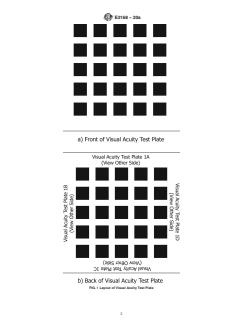
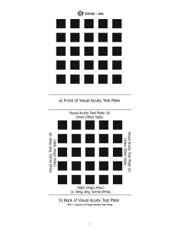
1.3 Each visual acuity test plate consists of 25 individual image areas. The images are arranged in 5 rows and 5 columns as shown in Fig. 1. Each image area is 2 in. x 2 in. (51 mm x 51 mm). All identification is on the back side of the plate. Each plate can be viewed from any of the four orientations (that is, it can be viewed with any of the four edges “up” on the illuminator). Since there are five different plates in the set, this makes for a total of 20 different patterns that can be viewed. The identification of whi...
General Information
- Status
- Published
- Publication Date
- 30-Nov-2020
- Technical Committee
- E07 - Nondestructive Testing
- Drafting Committee
- E07.02 - Reference Radiological Images
Relations
- Effective Date
- 01-Feb-2024
- Effective Date
- 01-Dec-2019
- Effective Date
- 01-Mar-2019
- Effective Date
- 01-Jan-2018
- Effective Date
- 15-Jun-2017
- Effective Date
- 01-Feb-2017
- Effective Date
- 01-Aug-2016
- Effective Date
- 01-Feb-2016
- Effective Date
- 01-Dec-2015
- Effective Date
- 01-Sep-2015
- Effective Date
- 01-Jun-2014
- Effective Date
- 01-Jun-2014
- Effective Date
- 01-Dec-2013
- Effective Date
- 15-Jun-2013
- Effective Date
- 01-Jun-2013
Overview
ASTM E3168-20a is the Standard Practice for Determining Low-Contrast Visual Acuity of Radiographic Interpreters, developed by ASTM International. This standard specifies methods for evaluating the ability of individuals to detect low-contrast linear images under radiographic interpretation conditions. It is especially relevant for nondestructive testing and quality assurance in industries requiring precise radiographic interpretation.
The standard prescribes the use of visual acuity test plates, each containing patterns of varying radiographic noise, contrast, and sharpness, viewed in an environment similar to that used in real-world film interpretation. By following ASTM E3168-20a, organizations can ensure that radiographic interpreters maintain required visual acuity for accurate detection of features in industrial radiographs.
Key Topics
Low-Contrast Visual Acuity Testing
Evaluates an interpreter’s ability to resolve faint, blurred, or subtle linear indications in low-light, radiographic viewing environments.Test Procedure
Involves viewing test plates (each with 25 image areas) on a compliant radiographic viewer. The interpreter records the position and orientation of perceived slit images, ensuring there is no use of optical magnification. Tests are administered by certified personnel under controlled conditions.Performance Benchmarks
Data from round robin testing shows certified radiographers typically score above 85%, providing a statistical basis for acceptance criteria. Test records should be maintained to establish organization-specific benchmarks.Viewing Environment
The standard recommends compliance with ASTM E1390 for viewers and ASTM E94 for viewing environment. These controls ensure uniform test conditions and eliminate variables such as stray lighting and incorrect luminance.Administration and Record-Keeping
Tests are administered by qualified personnel, such as a certified Radiographic Testing Level III or licensed eye care professionals. Documentation includes interpreter identification, test plate/orientation, environmental conditions, and test scores.Corrective Action
If acceptable scores are not achieved, corrective measures include adjusting lighting, reviewing adaptation time, managing eye fatigue, or referring the interpreter for professional vision examination.
Applications
Nondestructive Testing (NDT)
Ensures interpreters of industrial radiographs have the visual capacity to discern critical low-contrast features essential for flaw detection and quality control.Personnel Qualification
Supports compliance with certification and training protocols in accordance with ISO 9712, ASNT SNT-TC-1A, and other NDT personnel qualification standards.Regular Visual Assessment
Used by organizations as part of routine visual examinations and annual competency checks for radiographic interpreters.Quality Assurance Records
Provides a documented, standardized basis for recording visual acuity test results as part of broader quality management systems in manufacturing, aerospace, and power generation industries.
Related Standards
ASTM E94 - Guide for Radiographic Examination Using Industrial Radiographic Film
Provides requirements for film evaluation environments and procedures as referenced in E3168-20a.ASTM E1390 - Specification for Illuminators Used for Viewing Industrial Radiographs
Details technical specifications for viewers used in visual acuity testing.ASTM E1316 - Terminology for Nondestructive Examinations
Standard definitions relevant to radiography and testing procedures.ISO 9712 - NDT - Qualification and Certification of NDT Personnel
International guidelines related to the certification of nondestructive testing professionals.ASNT SNT-TC-1A / ANSI/ASNT-CP-189 / NAS 410
Additional practices and standards for personnel qualification and certification in nondestructive testing.
Keywords: low-contrast visual acuity, radiographic interpreter, nondestructive testing, ASTM E3168-20a, visual acuity testing, radiographic film interpretation, personnel qualification, industrial radiography, quality assurance
Buy Documents
ASTM E3168-20a - Standard Practice for Determining Low-Contrast Visual Acuity of Radiographic Interpreters

REDLINE ASTM E3168-20a - Standard Practice for Determining Low-Contrast Visual Acuity of Radiographic Interpreters
Get Certified
Connect with accredited certification bodies for this standard

IMP NDT d.o.o.
Non-destructive testing services. Radiography, ultrasonic, magnetic particle, penetrant, visual inspection.
Inštitut za kovinske materiale in tehnologije
Institute of Metals and Technology. Materials testing, metallurgical analysis, NDT.
Q Techna d.o.o.
NDT and quality assurance specialist. 30+ years experience. NDT personnel certification per ISO 9712, nuclear and thermal power plant inspections, QA/
Sponsored listings
Frequently Asked Questions
ASTM E3168-20a is a standard published by ASTM International. Its full title is "Standard Practice for Determining Low-Contrast Visual Acuity of Radiographic Interpreters". This standard covers: SIGNIFICANCE AND USE 4.1 This practice is used to evaluate the ability of a radiographic interpreter to discriminate low contrast slit images in a radiographic interpretation environment. A radiographic viewer, as described in Specification E1390, and a viewing environment, as described in Guide E94, are strongly recommended. The minimum acceptable test score in any given application depends on the requirements of the application. Using parties should develop and maintain records of their test results to guide the establishment of acceptable test scores for their applications. (See Note 1.) Note 1: During round robin testing with experienced radiographic interpreters, 76 % of the interpreters achieved a score of 85 % or higher, and 95 % achieved a score of 80 % or higher. The average score was 90.7 %, and the standard deviation was 6.7 %. In a second study from 2017, with both certified radiographers and uncertified personnel, the average and standard deviation among certified radiographers was 90.4 ± 4.0 % and among uncertified personnel was 88.4 ± 4.9 %. It was found that on each test page there are 3 or 4 images where the average score for each was less than 80 % correct and the remainder of the images all individually scored greater than 80 % on average. A limited number of the general public was examined, and the average score among these was 75.0 ± 3.3 %. 4.2 Administration of the Test 4.2.1 The test procedure described in this practice is intended to determine the ability of a radiographic interpreter to detect low contrast images in a low light level environment. Appropriate dark adaptation time should be permitted. A minimum of 1 min is recommended; however, longer dark adaptation times may be required by some users. 4.2.2 The test shall be administered by or under the direction of a test administrator (see 3.2.4). The individual being tested shall not know the identification of the plate or orientation prior to the test. 4.2.3 The interpretation of each of the ... SCOPE 1.1 This practice details the procedure for determining the low-contrast visual acuity of a radiographic interpreter by evaluating the ability of the individual to detect linear images of varying radiographic noise, contrast, and sharpness. No statement is made regarding the applicability of these images to evaluate the competence of a radiographic interpreter. There is no correlation between these images of slit phantoms and the ability to detect cracks or other linear features in an actual radiographic examination. The test procedure follows from work performed by the National Institute of Standards and Technology presented in NBS Technical Note 1143, issued June 1981. 1.2 The visual acuity test set consists of five individual plates, each containing a series of radiographic images of 0.5 in. (12.7 mm) long slits in thin metal shims. The original radiographs used to prepare the illustrations were generated using various absorbers, geometric parameters (unsharpness, slit widths), and source parameters (kV, mA, time) to produce images of varying noise, contrast, and sharpness. Each radiographic image has a background density of 1.8 ± 0.15. The images are viewed in a radiographic interpretation environment as used for the evaluation of production radiographic films, for example, illuminators and background lighting as described in Guide E94 and Specification E1390, and without optical magnification. 1.3 Each visual acuity test plate consists of 25 individual image areas. The images are arranged in 5 rows and 5 columns as shown in Fig. 1. Each image area is 2 in. x 2 in. (51 mm x 51 mm). All identification is on the back side of the plate. Each plate can be viewed from any of the four orientations (that is, it can be viewed with any of the four edges “up” on the illuminator). Since there are five different plates in the set, this makes for a total of 20 different patterns that can be viewed. The identification of whi...
SIGNIFICANCE AND USE 4.1 This practice is used to evaluate the ability of a radiographic interpreter to discriminate low contrast slit images in a radiographic interpretation environment. A radiographic viewer, as described in Specification E1390, and a viewing environment, as described in Guide E94, are strongly recommended. The minimum acceptable test score in any given application depends on the requirements of the application. Using parties should develop and maintain records of their test results to guide the establishment of acceptable test scores for their applications. (See Note 1.) Note 1: During round robin testing with experienced radiographic interpreters, 76 % of the interpreters achieved a score of 85 % or higher, and 95 % achieved a score of 80 % or higher. The average score was 90.7 %, and the standard deviation was 6.7 %. In a second study from 2017, with both certified radiographers and uncertified personnel, the average and standard deviation among certified radiographers was 90.4 ± 4.0 % and among uncertified personnel was 88.4 ± 4.9 %. It was found that on each test page there are 3 or 4 images where the average score for each was less than 80 % correct and the remainder of the images all individually scored greater than 80 % on average. A limited number of the general public was examined, and the average score among these was 75.0 ± 3.3 %. 4.2 Administration of the Test 4.2.1 The test procedure described in this practice is intended to determine the ability of a radiographic interpreter to detect low contrast images in a low light level environment. Appropriate dark adaptation time should be permitted. A minimum of 1 min is recommended; however, longer dark adaptation times may be required by some users. 4.2.2 The test shall be administered by or under the direction of a test administrator (see 3.2.4). The individual being tested shall not know the identification of the plate or orientation prior to the test. 4.2.3 The interpretation of each of the ... SCOPE 1.1 This practice details the procedure for determining the low-contrast visual acuity of a radiographic interpreter by evaluating the ability of the individual to detect linear images of varying radiographic noise, contrast, and sharpness. No statement is made regarding the applicability of these images to evaluate the competence of a radiographic interpreter. There is no correlation between these images of slit phantoms and the ability to detect cracks or other linear features in an actual radiographic examination. The test procedure follows from work performed by the National Institute of Standards and Technology presented in NBS Technical Note 1143, issued June 1981. 1.2 The visual acuity test set consists of five individual plates, each containing a series of radiographic images of 0.5 in. (12.7 mm) long slits in thin metal shims. The original radiographs used to prepare the illustrations were generated using various absorbers, geometric parameters (unsharpness, slit widths), and source parameters (kV, mA, time) to produce images of varying noise, contrast, and sharpness. Each radiographic image has a background density of 1.8 ± 0.15. The images are viewed in a radiographic interpretation environment as used for the evaluation of production radiographic films, for example, illuminators and background lighting as described in Guide E94 and Specification E1390, and without optical magnification. 1.3 Each visual acuity test plate consists of 25 individual image areas. The images are arranged in 5 rows and 5 columns as shown in Fig. 1. Each image area is 2 in. x 2 in. (51 mm x 51 mm). All identification is on the back side of the plate. Each plate can be viewed from any of the four orientations (that is, it can be viewed with any of the four edges “up” on the illuminator). Since there are five different plates in the set, this makes for a total of 20 different patterns that can be viewed. The identification of whi...
ASTM E3168-20a is classified under the following ICS (International Classification for Standards) categories: 19.100 - Non-destructive testing. The ICS classification helps identify the subject area and facilitates finding related standards.
ASTM E3168-20a has the following relationships with other standards: It is inter standard links to ASTM E1316-24, ASTM E1316-19b, ASTM E1316-19, ASTM E1316-18, ASTM E1316-17a, ASTM E1316-17, ASTM E1316-16a, ASTM E1316-16, ASTM E1316-15a, ASTM E1316-15, ASTM E1316-14, ASTM E1316-14e1, ASTM E1316-13d, ASTM E1316-13c, ASTM E1316-13b. Understanding these relationships helps ensure you are using the most current and applicable version of the standard.
ASTM E3168-20a is available in PDF format for immediate download after purchase. The document can be added to your cart and obtained through the secure checkout process. Digital delivery ensures instant access to the complete standard document.
Standards Content (Sample)
This international standard was developed in accordance with internationally recognized principles on standardization established in the Decision on Principles for the
Development of International Standards, Guides and Recommendations issued by the World Trade Organization Technical Barriers to Trade (TBT) Committee.
Designation: E3168 − 20a
Standard Practice for
Determining Low-Contrast Visual Acuity of Radiographic
Interpreters
This standard is issued under the fixed designation E3168; the number immediately following the designation indicates the year of
original adoption or, in the case of revision, the year of last revision. A number in parentheses indicates the year of last reapproval. A
superscript epsilon (´) indicates an editorial change since the last revision or reapproval.
1. Scope* makes for a total of 20 different patterns that can be viewed.
The identification of which of the five plates and which of the
1.1 This practice details the procedure for determining the
four orientations were viewed in any given test can be
low-contrast visual acuity of a radiographic interpreter by
determined from the designation on the back side.
evaluating the ability of the individual to detect linear images
1.4 Within the image areas, the slit image may appear in any
of varying radiographic noise, contrast, and sharpness. No
statement is made regarding the applicability of these images to of five locations, that is, in any of the four corners of the image
area, or near the center. No more than one slit image will
evaluate the competence of a radiographic interpreter. There is
no correlation between these images of slit phantoms and the appear in any one image area. The slit image may be
horizontal, vertical, slant left, or slant right. Several of the
ability to detect cracks or other linear features in an actual
radiographic examination. The test procedure follows from plates include one or more image areas in which there is no slit
image.
work performed by the National Institute of Standards and
Technology presented in NBS Technical Note 1143, issued
1.5 Use of this standard requires procurement of the adjunct
June 1981.
test plates.
1.2 The visual acuity test set consists of five individual
1.6 This standard does not purport to address all of the
plates, each containing a series of radiographic images of
safety concerns, if any, associated with its use. It is the
0.5 in. (12.7 mm) long slits in thin metal shims. The original
responsibility of the user of this standard to establish appro-
radiographs used to prepare the illustrations were generated
priate safety, health, and environmental practices and deter-
using various absorbers, geometric parameters (unsharpness,
mine the applicability of regulatory limitations prior to use.
slit widths), and source parameters (kV, mA, time) to produce
1.7 This international standard was developed in accor-
images of varying noise, contrast, and sharpness. Each radio-
dance with internationally recognized principles on standard-
graphic image has a background density of 1.8 6 0.15. The
ization established in the Decision on Principles for the
images are viewed in a radiographic interpretation environment
Development of International Standards, Guides and Recom-
as used for the evaluation of production radiographic films, for
mendations issued by the World Trade Organization Technical
example, illuminators and background lighting as described in
Barriers to Trade (TBT) Committee.
Guide E94 and Specification E1390, and without optical
2. Referenced Documents
magnification.
2.1 ASTM Standards:
1.3 Each visual acuity test plate consists of 25 individual
E94 Guide for Radiographic Examination Using Industrial
image areas. The images are arranged in 5 rows and 5 columns
Radiographic Film
as shown in Fig. 1. Each image area is 2 in. x 2 in. (51 mm x
E1316 Terminology for Nondestructive Examinations
51 mm). All identification is on the back side of the plate. Each
E1390 Specification for Illuminators Used for Viewing In-
plate can be viewed from any of the four orientations (that is,
dustrial Radiographs
it can be viewed with any of the four edges “up” on the
2.2 ASTM Adjuncts:
illuminator). Since there are five different plates in the set, this
5 Visual Acuity Test Plates and Answer Key
1 2
This practice is under the jurisdiction of ASTM Committee E07 on Nonde- For referenced ASTM standards, visit the ASTM website, www.astm.org, or
structive Testing and is the direct responsibility of Subcommittee E07.02 on contact ASTM Customer Service at service@astm.org. For Annual Book of ASTM
Reference Radiological Images. Standards volume information, refer to the standard’s Document Summary page on
Current edition approved Dec. 1, 2020. Published January 2021. Originally the ASTM website.
approved in 2020. Last previous edition approved in 2020 as E3168 – 20. DOI: Available from ASTM International Headquarters. Order Reference Radio-
10.1520/E3168-20A. graph RRE3168.
*A Summary of Changes section appears at the end of this standard
Copyright © ASTM International, 100 Barr Harbor Drive, PO Box C700, West Conshohocken, PA 19428-2959. United States
E3168 − 20a
FIG. 1 Layout of Visual Acuity Test Plate
E3168 − 20a
2.3 NIST Document: mended. The minimum acceptable test score in any given
NBS Technical Note 1143 Visual Acuity Testing of Radio- application depends on the requirements of the application.
graphic Inspectors in Nondestructive Inspection Using parties should develop and maintain records of their test
2.4 AIA Document: results to guide the establishment of acceptable test scores for
NAS 410 Certification & Qualification of Nondestructive
their applications. (See Note 1.)
Test Personnel
6 NOTE 1—During round robin testing with experienced radiographic
2.5 ASNT Documents:
interpreters, 76 % of the interpreters achieved a score of 85 % or higher,
SNT-TC-1A Recommended Practice for Personnel Qualifi-
and 95 % achieved a score of 80 % or higher. The average score was
cation and Certification in Nondestructive Testing
90.7 %, and the standard deviation was 6.7 %. In a second study from
2017, with both certified radiographers and uncertified personnel, the
ANSI/ASNT-CP-189 ASNT Standard for Qualification and
average and standard deviation among certified radiographers was 90.4 6
Certification of Nondestructive Testing Personnel
4.0 % and among uncertified personnel was 88.4 6 4.9 %. It was found
2.6 ANSI/ISO Standard:
that on each test page there are 3 or 4 images where the average score for
ISO 9712 NDT—Qualification and Certification of NDT
each was less than 80 % correct and the remainder of the images all
Personnel
individually scored greater than 80 % on average. A limited number of the
general public was examined, and the average score among these was 75.0
3. Terminology
6 3.3 %.
3.1 Definitions—Definitions relating to radiographic exami-
4.2 Administration of the Test
nations which appear in Terminology E1316 shall apply to
4.2.1 The test procedure described in this practice is in-
terms used in this standard.
tended to determine the ability of a radiographic interpreter to
3.2 Definitions of Terms Specific to This Standard:
detect low contrast images in a low light level environment.
3.2.1 answer master, n—a representation of the answer
Appropriate dark adaptation time should be permitted. A
sheet, provided with the adjunct set showing the correct
minimum of 1 min is recommended; however, longer dark
answers for each of the 25 reading locations in the correspond-
adaptation times may be required by some users.
ing test plate.
4.2.2 The test shall be administered by or under the direc-
3.2.2 low-contrast visual acuity, n—the ability of an indi-
tion of a test administrator (see 3.2.4). The individual being
vidual to resolve faint, blurred linear indications in a low-light- tested shall not know the identification of the plate or orienta-
level environment typical of the radiographic interpretation
tion prior to the test.
environment.
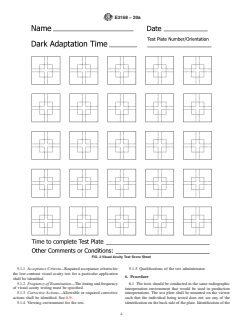
4.2.3 The interpretation of each of the 25 image areas on a
3.2.3 slit image, n—a linear indication produced by radio- plate is recorded on an answer sheet, Fig. 2, by drawing a line
graphic techniques of a 0.5 in. (12.7 mm) slit in a shim. corresponding to the location and orientation of the slit image
3.2.3.1 Discussion—As printed, the image appears as a in that image area. Where no line image is detected, a circle
slightly darker line, approximately 0.6 in. (15 mm) long in a should be drawn on the answer sheet in the area corresponding
slightly lighter background. In some images, the line may to the image area in which no slit image was detected. An
appear discontinuous, but will be straight and of the appropri-
example score sheet is given in Fig. 3, illustrating typical line
ate length. locations and orientations and illustrating the method for
marking answers. The markings shown in the sample score
3.2.4 test administrator, n—(1) a certified Radiographic
sheet are not taken from any of the actual test plates; however,
Testing Level III in accordance with a nationally or interna-
they illustrate typical distributions of slit images. Fig. 2 of this
tionally recognized NDT personnel qualification practice or
practice may be photocopied to provide answer sheets, or the
standard, such as ANSI/ASNT-CP-189, SNT-TC-1A, NAS
using organization may generate their own suitable answer
410, ISO 9712, or a similar document and certified by the
sheet. In any case, the answer sheet must have provisions for
employer or agency, as applicable; or (2) a licensed optometrist
recording both the location and orientation of the indication in
or opthalmologist.
each of the 25 image locations.
4. Significance and Use
4.2.4 The order in which the indications
...
This document is not an ASTM standard and is intended only to provide the user of an ASTM standard an indication of what changes have been made to the previous version. Because
it may not be technically possible to adequately depict all changes accurately, ASTM recommends that users consult prior editions as appropriate. In all cases only the current version
of the standard as published by ASTM is to be considered the official document.
Designation: E3168 − 20 E3168 − 20a
Standard Practice for
Determining Low-Contrast Visual Acuity of Radiographic
Interpreters
This standard is issued under the fixed designation E3168; the number immediately following the designation indicates the year of
original adoption or, in the case of revision, the year of last revision. A number in parentheses indicates the year of last reapproval. A
superscript epsilon (´) indicates an editorial change since the last revision or reapproval.
1. Scope Scope*
1.1 This practice details the procedure for determining the low-contrast visual acuity of a radiographic interpreter by evaluating
the ability of the individual to detect linear images of varying radiographic noise, contrast, and sharpness. No statement is made
regarding the applicability of these images to evaluate the competence of a radiographic interpreter. There is no correlation between
these images of slit phantoms and the ability to detect cracks or other linear features in an actual radiographic examination. The
test procedure follows from work performed by the National Institute of Standards and Technology presented in NBS Technical
Note 1143, issued June 1981.
1.2 The visual acuity test set consists of five individual plates, each containing a series of radiographic images of 0.5 in. (12.7 mm)
long slits in thin metal shims. The original radiographs used to prepare the illustrations were generated using various absorbers,
geometric parameters (unsharpness, slit widths), and source parameters (kV, mA, time) to produce images of varying noise,
contrast, and sharpness. Each radiographic image has a background density of 1.8 6 0.15. The images are viewed in a radiographic
interpretation environment as used for the evaluation of production radiographic films, for example, illuminators and background
lighting as described in Guide E94 and Specification E1390, and without optical magnification.
1.3 Each visual acuity test plate consists of 25 individual image areas. The images are arranged in 5 rows and 5 columns as shown
in Fig. 1. Each image area is 2 in. x 2 in. (51 mm x 51 mm). All identification is on the back side of the plate. Each plate can be
viewed from any of the four orientations (that is, it can be viewed with any of the four edges “up” on the illuminator). Since there
are five different plates in the set, this makes for a total of 20 different patterns that can be viewed. The identification of which
of the five plates and which of the four orientations were viewed in any given test can be determined from the designation on the
back side.
1.4 Within the image areas, the slit image may appear in any of five locations, that is, in any of the four corners of the image area,
or near the center. No more than one slit image will appear in any one image area. The slit image may be horizontal, vertical, slant
left, or slant right. Several of the plates include one or more image areas in which there is no slit image.
1.5 Use of this standard requires procurement of the adjunct test plates.
1.6 This standard does not purport to address all of the safety concerns, if any, associated with its use. It is the responsibility
of the user of this standard to establish appropriate safety, health, and environmental practices and determine the applicability of
regulatory limitations prior to use.
This practice is under the jurisdiction of ASTM Committee E07 on Nondestructive Testing and is the direct responsibility of Subcommittee E07.02 on Reference
Radiological Images.
Current edition approved Feb. 1, 2020Dec. 1, 2020. Published March 2020January 2021. Originally approved in 2020. Last previous edition approved in 2020 as
E3168 – 20. DOI: 10.1520/3168-20.10.1520/E3168-20A.
*A Summary of Changes section appears at the end of this standard
Copyright © ASTM International, 100 Barr Harbor Drive, PO Box C700, West Conshohocken, PA 19428-2959. United States
E3168 − 20a
FIG. 1 Layout of Visual Acuity Test Plate
E3168 − 20a
1.7 This international standard was developed in accordance with internationally recognized principles on standardization
established in the Decision on Principles for the Development of International Standards, Guides and Recommendations issued
by the World Trade Organization Technical Barriers to Trade (TBT) Committee.
2. Referenced Documents
2.1 ASTM Standards:
E94 Guide for Radiographic Examination Using Industrial Radiographic Film
E1316 Terminology for Nondestructive Examinations
E1390 Specification for Illuminators Used for Viewing Industrial Radiographs
2.2 ASTM Adjuncts:
5 Visual Acuity Test Plates and Answer Key
2.3 NIST Document:
NBS Technical Note 1143 Visual Acuity Testing of Radiographic Inspectors in Nondestructive Inspection
2.4 AIA Document:
NAS 410 Certification & Qualification of Nondestructive Test Personnel
2.5 ASNT Documents:
SNT-TC-1A Recommended Practice for Personnel Qualification and Certification in Nondestructive Testing
ANSI/ASNT-CP-189 ASNT Standard for Qualification and Certification of Nondestructive Testing Personnel
2.6 ANSI/ISO Standard:
ISO 9712 NDT—Qualification and Certification of NDT Personnel
3. Terminology
3.1 Definitions—Definitions relating to radiographic examinations which appear in Terminology E1316 shall apply to terms used
in this standard.
3.2 Definitions of Terms Specific to This Standard:
3.2.1 answer master, n—a representation of the answer sheet, provided with the adjunct set showing the correct answers for each
of the 25 reading locations in the corresponding test plate.
3.2.2 low-contrast visual acuity, n—the ability of an individual to resolve faint, blurred linear indications in a low-light-level
environment typical of the radiographic interpretation environment.
3.2.3 slit image, n—a linear indication produced by radiographic techniques of a 0.5 in. (12.7 mm) slit in a shim.
3.2.3.1 Discussion—
As printed, the image appears as a slightly darker line, approximately 0.6 in. (15 mm) long in a slightly lighter background. In some
images, the line may appear discontinuous, but will be straight and of the appropriate length.
3.2.4 test administrator, n—(1) a certified Radiographic Testing Level III in accordance with a nationally or internationally
recognized NDT personnel qualification practice or standard, such as ANSI/ASNT-CP-189, SNT-TC-1A, NAS 410, ISO 9712, or
a similar document and certified by the employer or agency, as applicable; or (2) a licensed optometrist or opthalmologist.
4. Significance and Use
4.1 This practice is used to evaluate the ability of a radiographic interpreter to discriminate low contrast slit images in a
radiographic interpretation environment. A radiographic viewer, as described in Specification E1390, and a viewing environment,
as described in Guide E94, are strongly recommended. The minimum acceptable test score in any given application depends on
For referenced ASTM standards, visit the ASTM website, www.astm.org, or contact ASTM Customer Service at service@astm.org. For Annual Book of ASTM Standards
volume information, refer to the standard’s Document Summary page on the ASTM website.
Available from ASTM International Headquarters. Order Reference Radiograph RRE3168.
Available from National Institute of Standards and Technology (NIST), 100 Bureau Dr., Stop 1070, Gaithersburg, MD 20899-1070, http://www.nist.gov.
Available from Aerospace Industries Association (AIA), 1000 Wilson Blvd., Suite 1700, Arlington, VA 22209, http://www.aia-aerospace.org.
Available from American Society for Nondestructive Testing (ASNT), P.O. Box 28518, 1711 Arlingate Ln., Columbus, OH 43228-0518, http://www.asnt.org.
Available from International Organization for Standardization (ISO), ISO Central Secretariat, Chemin de Blandonnet 8, CP 401, 1214 Vernier, Geneva, Switzerland,
https://www.iso.org.
E3168 − 20a
the requirements of the application. Using parties should develop and maintain records of their test results to guide the
establishment of acceptable test scores for their applications. (See Note 1.)
NOTE 1—During round robin testing with experienced radiographic interpreters, 76 % of the interpreters achieved a score of 85 % or higher, and 95 %
achieved a score of 80 % or higher. The average score was 90.7 %, and the standard deviation was 6.7 %. In a second study from 2017, with both certified
radiographers and uncertified personnel, the average and standard deviation among certified radiographers was 90.4 6 4.0 % and among uncertified
personnel was 88.4 6 4.9 %. It was found that on each test page there are 3 or 4 images where the average score for each was less than 80 % correct
and the remainder of the images all individually scored greater than 80 % on average. A limited number of the general public was examined, and the
average score among these was 75.0 6 3.3 %.
4.2 Administration of the Test
4.2.1 The test procedure described in this practice is intended to determine the ability of a radiographic interpreter to detect low
contrast images in a low light level environment. Appropriate dark adaptation time should be permitted. A minimum of 1 min is
recommended; however, longer dark adaptation times may be required by some users.
4.2.2 The test shouldshall be administered by or under the direction of a test administrator. administrator (see 3.2.4). The
individual being tested shall not know the identification of the plate or orientation prior to the test.
...
Questions, Comments and Discussion
Ask us and Technical Secretary will try to provide an answer. You can facilitate discussion about the standard in here.
Loading comments...