


ASTM E908-98(2018)
(Practice)Standard Practice for Calibrating Gaseous Reference Leaks
Standard Practice for Calibrating Gaseous Reference Leaks
ABSTRACT
This practice establishes the standard procedures for calibrating leak artifacts of a specified gas, that may be used for determining the response of leak detectors, or in other situations where a known small flow of gas is required. The purpose of this practice is to establish calibration without reference to other calibrated leaks in as straightforward a manner as possible using the likeliest available equipment. The two types of leaks considered here are Type I, which is pressure to vacuum, and Type II, which is pressure to atmosphere. Three calibration methods are described under each type of reference leak, as follows: Method A—accumulation comparison using a known volume of tracer gas at specified conditions of temperature and pressure as a reference; Method B—accumulation comparison using a reference leak artifact calibrated using Method A; and Method C—direct measurement of leak rate by timing the movement (displacement) of a liquid slug, by the leak, in a capillary tube of known dimensions.
SCOPE
1.1 This practice covers procedures for calibrating leak artifacts of a specified gas, that may be used for determining the response of leak detectors, or in other situations where a known small flow of gas is required. The purpose of this practice is to establish calibration without reference to other calibrated leaks in as straightforward a manner as possible using the likeliest available equipment. While the uncertainties associated with these procedures will most likely be greater than those obtained via traceable calibration chains (on the order of 10 %), these procedures allow independent means of establishing or verifying the leakage rate from leak artifacts of questionable history, or when traceable leak artifacts are not available.
1.2 Two types of leaks are considered:
1.2.1 Type I—Pressure to vacuum.
1.2.2 Type II—Pressure to atmosphere.
1.3 Three calibration methods are described under each type of reference leak:
1.3.1 Method A—Accumulation comparison, using a known volume of gas at specified conditions of temperature and pressure as a reference.
1.3.2 Method B—Accumulation comparison, using a leak artifact calibrated using Method A.
1.3.3 Method C—Displacement of a liquid slug, by the leak, in capillary tube of known dimensions.
1.4 The values stated in inch-pound units are to be regarded as standard. The values given in parentheses are mathematical conversions to SI units that are provided for information only and are not considered standard.
1.5 This standard does not purport to address all of the safety concerns, if any, associated with its use. It is the responsibility of the user of this standard to establish appropriate safety, health, and environmental practices and determine the applicability of regulatory limitations prior to use.
1.6 This international standard was developed in accordance with internationally recognized principles on standardization established in the Decision on Principles for the Development of International Standards, Guides and Recommendations issued by the World Trade Organization Technical Barriers to Trade (TBT) Committee.
General Information
Buy Standard
Standards Content (Sample)
NOTICE: This standard has either been superseded and replaced by a new version or withdrawn.
Contact ASTM International (www.astm.org) for the latest information
Designation: E908 − 98 (Reapproved 2018)
Standard Practice for
Calibrating Gaseous Reference Leaks
This standard is issued under the fixed designation E908; the number immediately following the designation indicates the year of
original adoption or, in the case of revision, the year of last revision.Anumber in parentheses indicates the year of last reapproval.A
superscript epsilon (´) indicates an editorial change since the last revision or reapproval.
1. Scope 1.6 This international standard was developed in accor-
dance with internationally recognized principles on standard-
1.1 This practice covers procedures for calibrating leak
ization established in the Decision on Principles for the
artifacts of a specified gas, that may be used for determining
Development of International Standards, Guides and Recom-
the response of leak detectors, or in other situations where a
mendations issued by the World Trade Organization Technical
known small flow of gas is required. The purpose of this
Barriers to Trade (TBT) Committee.
practice is to establish calibration without reference to other
calibrated leaks in as straightforward a manner as possible
2. Referenced Documents
using the likeliest available equipment.While the uncertainties
associated with these procedures will most likely be greater 2.1 ASTM Standards:
E425Definitions of Terms Relating to Leak Testing (With-
than those obtained via traceable calibration chains (on the
order of 10%), these procedures allow independent means of drawn 1991)
E427PracticeforTestingforLeaksUsingtheHalogenLeak
establishing or verifying the leakage rate from leak artifacts of
questionable history, or when traceable leak artifacts are not Detector Alkali-Ion Diode (Withdrawn 2013)
E479Guide for Preparation of a Leak Testing Specification
available.
(Withdrawn 2014)
1.2 Two types of leaks are considered:
F134Test Methods for Determining Hermeticity of Electron
1.2.1 Type I—Pressure to vacuum.
Devices with a Helium Mass Spectrometer Leak Detector
1.2.2 Type II—Pressure to atmosphere.
(Withdrawn 1996)
1.3 Threecalibrationmethodsaredescribedundereachtype
2.2 Other Documents:
of reference leak: 4
AVS 2.2-1968Method for Vacuum Leak Calibration
1.3.1 MethodA—Accumulation comparison, using a known
Recommended Practices for the Calibration and Use of
volume of gas at specified conditions of temperature and 5
Leaks
pressure as a reference.
1.3.2 Method B—Accumulation comparison, using a leak
3. Summary of Practice
artifact calibrated using Method A.
3.1 Method A—Accumulation comparison, using a known
1.3.3 MethodC—Displacementofaliquidslug,bytheleak,
volume of tracer gas:
in capillary tube of known dimensions.
3.1.1 This method uses a closed chamber of nonreactive
1.4 The values stated in inch-pound units are to be regarded
material having a means of removing all tracer gas and a
as standard. The values given in parentheses are mathematical
connection to the tracer sensor.
conversions to SI units that are provided for information only
3.1.2 A small, known quantity of tracer gas is discharged
and are not considered standard.
intothechamberandtheresponserecordedforaperiodoftime
inwhichitisanticipatedtheunknownleakwillrequiretoreach
1.5 This standard does not purport to address all of the
safety concerns, if any, associated with its use. It is the the same concentration.
responsibility of the user of this standard to establish appro-
priate safety, health, and environmental practices and deter-
mine the applicability of regulatory limitations prior to use.
For referenced ASTM standards, visit the ASTM website, www.astm.org, or
contact ASTM Customer Service at service@astm.org. For Annual Book of ASTM
Standards volume information, refer to the standard’s Document Summary page on
the ASTM website.
1 3
This practice is under the jurisdiction of ASTM Committee E07 on Nonde- The last approved version of this historical standard is referenced on
structive Testing and is the direct responsibility of Subcommittee E07.08 on Leak www.astm.org.
Testing Method. AvailablefromAVS,AmericanVacuumSociety,335E.45thStreet,NewYork,
CurrenteditionapprovedJune1,2018.PublishedJuly2018.Originallyapproved N.Y., 10017.
in 1982. Last previous edition approved in 2012 as E908-98 (2012). DOI: C.D. Ehrlich and J.A. Basford, Journal of Vac. Sci, Technology, A(10), 1992,
10.1520/E0908-98R18. pp. 1–17.
Copyright © ASTM International, 100 Barr Harbor Drive, PO Box C700, West Conshohocken, PA 19428-2959. United States
E908 − 98 (2018)
3.1.3 The tracer gas is removed from the chamber, and the 3.3.1 The tube is closely coupled to the leak, and has a
unknown leak is allowed to discharge into it until the sensor vent/fill valve to allow gas filling or positioning of the slug, or
response equals that of 3.1.2. both, which is then driven by the leakage of the gas.
3.1.4 The leakage rate in mol/s can be calculated as: 3.3.2 Due to capillary “friction,” this method is limited to a
−10 3
minimum leak size of about 4×10 mol/s (1 µPa·m /s).
Q 5PV t·R·T (1)
~ !
m
where:
4. Interferences
P = pressure in known volume in atmospheres (1
4.1 Type I Leaks, atmosphere to vacuum, MethodsAand B:
atm=101 325 Pa),
4.1.1 Forthepurposesofthissection,itwillbeassumedthat
V = the volume of gas in cm introduced in 3.1.2,
the gas is helium and the detector is the mass spectrometer
t = the time in seconds required for the concentration in
tuned for helium.
3.1.3 to equal that in 3.1.2,
R = gas constant=82.06=1 atm cm /mol/K, and NOTE 1—Other gases or detectors, or both, can be used with little
difference in procedures or interferences.
T = absolute temperature, K.
4.1.2 PressureRise—Therewillinevitablybesomepressure
3.1.5 It will be observed that chamber volume and sensor
riseinaclosedevacuatedchamber,duetooutgassingandsmall
linearityarenotfactorsinthisequation.However,thechamber
leaks.This may cause a decrease in ionization efficiency in the
volume must be selected to give a concentration within the
spectrometer tube and thus a steadily declining signal as
sensorrange.Also,thisconcentrationmustalsobeachievedby
indicated in Fig. 1. However, this effect should be quite
theunknownleakdischargingintothechamberinareasonable
constant from run to run, and so largely cancel out in final
lengthoftimeandmustbeappropriatesoasnottosignificantly
result.
affect the equilibrium flow rate from the leak. This is particu-
4.1.3 Helium Signal Rise—There will usually be a notice-
larly true of permeation leaks.
ableincreaseinheliumsignalwhenthechamberisclosed,due
3.2 MethodB—Accumulationcomparisonusingareference
to outgassing and in-leakage from the atmosphere as indicated
leak as calibrated in Method A, 3.1:
in Fig. 1. Again, this will be a constant which mostly cancels
3.2.1 This method is a means of extending the primary
out.
calibration by a factor of up to 10, by comparing with
4.1.4 SpectrometerSensitivityDrift—Thiswillbenoticedas
previously-calibrated leak artifacts for longer periods of time.
variations in zero and in reading levels with the same helium
−12
For example, a 5×10 mol/s leak that calibrated in Method
input.Withproperlytunedandmaintainedsystemsoperatingat
−13
A at 300 s can be used for 30 s to calibrate a 5×10 mol/s
least one decade below maximum sensitivity, this should be a
leak.
minor effect.
3.2.2 When this method is used, it should be realized that
4.1.5 Leaks—All detectable valve leaks and leaks from the
the total possible error will be at least doubled.
atmosphere should be repaired.
3.3 Method C—Direct measurement of leak rate by timing 4.1.6 Barometric Variations—(Not applicable to sealed res-
the movement of a liquid slug in a capillary tube of known ervoir units.) If the gage used to measure the pressure in the
dimensions: known volume is of the gage type, then account must be made
FIG. 1 Typical Detector Curves and Deviation Limits
E908 − 98 (2018)
of the local barometric pressure when calculating the absolute 4.3.3 SensorSensitivityDrift—Thiswillbenoticedasvaria-
pressure. This is probably true for falling pressures of the tions in zero and reading levels with the same halogen input.
known volume near 1 atmosphere or less. With properly maintained systems operating at least one
4.1.7 Temperature Drift—Changes in temperature between decade below maximum sensitivity, this should be a minor
measurements may result in slight variations in indicated effect.
pressures. These should be recorded and compensated for 4.3.4 Barometric Variations—Substantial variations from
accordingly. standard atmosphere pressure should be corrected.
4.2 Type I Leaks, atmosphere to vacuum, Method C: 4.4 Type II Leaks, pressure to atmosphere, Method
4.2.1 Liquid Slug Friction—This can be appreciable in C—Same as Type I, Method C, in 4.2.
small capillaries. It should be measured and a correction made
5. Apparatus
for it.
4.2.2 Vapor Pressure of Liquid—Water is the recommended
5.1 Type I Leaks, pressure to vacuum, Methods A and B:
liquid, and has a vapor pressure of about 20 mm Hg (3 kPa) at
5.1.1 Mass Spectrometer with Remote Tube Tuned for
−15
room temperature. This gives a theoretical increase in leak Helium—Minimum resolution (5×10 mol/s) helium, when
3 −5
indication of 20/760 (3×10/1×10 ) or approximately 3%.
operated as a leak detector.
This correction should be added to the final result.
5.1.2 Helium Supply with Pressure Regulator and Flowme-
4.2.3 Excess Volume Between Leak and Capillary—This
ter (approximately 10 cm /s).
willcausedelayedandjerkymovementoftheslug,andshould
5.1.3 Stainless-Steel Chamber (see Fig. 2) with provisions
be kept to an absolute minimum.
for:
4.2.4 Dirty Capillary—Symptoms similar to 4.2.3.The slug
5.1.3.1 Attachment of spectrometer tube,
should move smoothly when capillary tube is held at an angle.
5.1.3.2 Liquid nitrogen trap,
−6
5.1.3.3 Vacuum pumping to at least 1×10 torr (130 µPa)
4.3 Type II Leaks, pressure to standard atmosphere, Meth-
with isolating valve,
ods A and B:
5.1.3.4 Ionization vacuum gage,
4.3.1 Forthepurposesofthissection,itwillbeassumedthat
5.1.3.5 Attachment of helium leak with isolating valve and
the gas is fluorocarbon and the detector is the alkali-ion
separate rough pumping means,
halogen detector diode. Other gases or detectors, or both, can
5.1.3.6 Measured helium volume device (see Fig. 3) (see
be used with little difference in procedures or interferences.
Note 2), and
4.3.2 Halogen Signal Rise—There will usually be a small
5.1.3.7 Strip chart or flat-bed recorder.
increase in halogen signal due to outgassing, particularly from
elastomers or plastics.With minimum use of these materials in
NOTE 2—Other types of calibrated volumes in this range may be
the chamber, no correction for this will ordinarily be needed. substituted.
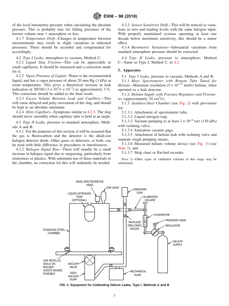
FIG. 2 Equipment for Calibrating Helium Leaks, Type I, Methods A and B
...
This document is not an ASTM standard and is intended only to provide the user of an ASTM standard an indication of what changes have been made to the previous version. Because
it may not be technically possible to adequately depict all changes accurately, ASTM recommends that users consult prior editions as appropriate. In all cases only the current version
of the standard as published by ASTM is to be considered the official document.
Designation: E908 − 98 (Reapproved 2012) E908 − 98 (Reapproved 2018)
Standard Practice for
Calibrating Gaseous Reference Leaks
This standard is issued under the fixed designation E908; the number immediately following the designation indicates the year of
original adoption or, in the case of revision, the year of last revision. A number in parentheses indicates the year of last reapproval. A
superscript epsilon (´) indicates an editorial change since the last revision or reapproval.
1. Scope
1.1 This practice covers procedures for calibrating leak artifacts of a specified gas, that may be used for determining the
response of leak detectors, or in other situations where a known small flow of gas is required. The purpose of this practice is to
establish calibration without reference to other calibrated leaks in as straightforward a manner as possible using the likeliest
available equipment. While the uncertainties associated with these procedures will most likely be greater than those obtained via
traceable calibration chains (on the order of 10 %), these procedures allow independent means of establishing or verifying the
leakage rate from leak artifacts of questionable history, or when traceable leak artifacts are not available.
1.2 Two types of leaks are considered:
1.2.1 Type I—Pressure to vacuum.
1.2.2 Type II—Pressure to atmosphere.
1.3 Three calibration methods are described under each type of reference leak:
1.3.1 Method A—Accumulation comparison, using a known volume of gas at specified conditions of temperature and pressure
as a reference.
1.3.2 Method B—Accumulation comparison, using a leak artifact calibrated using Method A.
1.3.3 Method C—Displacement of a liquid slug, by the leak, in capillary tube of known dimensions.
1.4 The values stated in inch-pound units are to be regarded as standard. The values given in parentheses are mathematical
conversions to SI units that are provided for information only and are not considered standard.
1.5 This standard does not purport to address all of the safety concerns, if any, associated with its use. It is the responsibility
of the user of this standard to establish appropriate safety safety, health, and healthenvironmental practices and determine the
applicability of regulatory limitations prior to use.
1.6 This international standard was developed in accordance with internationally recognized principles on standardization
established in the Decision on Principles for the Development of International Standards, Guides and Recommendations issued
by the World Trade Organization Technical Barriers to Trade (TBT) Committee.
2. Referenced Documents
2.1 ASTM Standards:
E425 Definitions of Terms Relating to Leak Testing (Withdrawn 1991)
E427 Practice for Testing for Leaks Using the Halogen Leak Detector Alkali-Ion Diode (Withdrawn 2013)
E479 Guide for Preparation of a Leak Testing Specification (Withdrawn 2014)
F134 Test Methods for Determining Hermeticity of Electron Devices with a Helium Mass Spectrometer Leak Detector
(Withdrawn 1996)
2.2 Other Documents:
AVS 2.2-1968 Method for Vacuum Leak Calibration
Recommended Practices for the Calibration and Use of Leaks
This practice is under the jurisdiction of ASTM Committee E07 on Nondestructive Testing and is the direct responsibility of Subcommittee E07.08 on Leak Testing
Method.
Current edition approved Nov. 15, 2012June 1, 2018. Published November 2012July 2018. Originally approved in 1982. Last previous edition approved in 20042012 as
E908 - 98 (2004).(2012). DOI: 10.1520/E0908-98R12.10.1520/E0908-98R18.
For referenced ASTM standards, visit the ASTM website, www.astm.org, or contact ASTM Customer Service at service@astm.org. For Annual Book of ASTM Standards
volume information, refer to the standard’s Document Summary page on the ASTM website.
The last approved version of this historical standard is referenced on www.astm.org.
Available from AVS, American Vacuum Society, 335 E. 45th Street, New York, N.Y., 10017.
C.D. Ehrlich and J.A. Basford, Journal of Vac. Sci, Technology, A(10), 1992, pp. 1–17.
Copyright © ASTM International, 100 Barr Harbor Drive, PO Box C700, West Conshohocken, PA 19428-2959. United States
E908 − 98 (2018)
3. Summary of Practice
3.1 Method A—Accumulation comparison, using a known volume of tracer gas:
3.1.1 This method uses a closed chamber of nonreactive material having a means of removing all tracer gas and a connection
to the tracer sensor.
3.1.2 A small, known quantity of tracer gas is discharged into the chamber and the response recorded for a period of time in
which it is anticipated the unknown leak will require to reach the same concentration.
3.1.3 The tracer gas is removed from the chamber, and the unknown leak is allowed to discharge into it until the sensor response
equals that of 3.1.2.
3.1.4 The leakage rate in mol/s can be calculated as:
Q 5 PV t·R·T (1)
~ !
m
where:
P = pressure in known volume in atmospheres (1 atm = 101 325 Pa),
V = the volume of gas in cm introduced in 3.1.2,
t = the time in seconds required for the concentration in 3.1.3 to equal that in 3.1.2,
R = gas constant = 82.06 = 1 atm cm /mol/K, and
T = absolute temperature, K.
3.1.5 It will be observed that chamber volume and sensor linearity are not factors in this equation. However, the chamber
volume must be selected to give a concentration within the sensor range. Also, this concentration must also be achieved by the
unknown leak discharging into the chamber in a reasonable length of time and must be appropriate so as not to significantly affect
the equilibrium flow rate from the leak. This is particularly true of permeation leaks.
3.2 Method B—Accumulation comparison using a reference leak as calibrated in Method A, 3.1:
3.2.1 This method is a means of extending the primary calibration by a factor of up to 10, by comparing with
−12
previously-calibrated leak artifacts for longer periods of time. For example, a 5 × 10 mol/s leak that calibrated in Method A at
−13
300 s can be used for 30 s to calibrate a 5 × 10 mol/s leak.
3.2.2 When this method is used, it should be realized that the total possible error will be at least doubled.
3.3 Method C—Direct measurement of leak rate by timing the movement of a liquid slug in a capillary tube of known
dimensions:
3.3.1 The tube is closely coupled to the leak, and has a vent/fill valve to allow gas filling or positioning of the slug, or both,
which is then driven by the leakage of the gas.
−10 3
3.3.2 Due to capillary “friction,” this method is limited to a minimum leak size of about 4 × 10 mol/s (1 μPa·m /s).
4. Interferences
4.1 Type I Leaks, atmosphere to vacuum, Methods A and B:
4.1.1 For the purposes of this section, it will be assumed that the gas is helium and the detector is the mass spectrometer tuned
for helium.
NOTE 1—Other gases or detectors, or both, can be used with little difference in procedures or interferences.
4.1.2 Pressure Rise—There will inevitably be some pressure rise in a closed evacuated chamber, due to outgassing and small
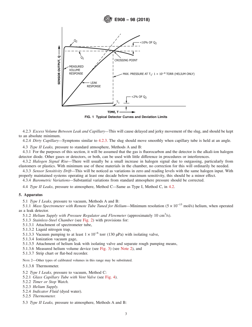
leaks. This may cause a decrease in ionization efficiency in the spectrometer tube and thus a steadily declining signal as indicated
in Fig. 1. However, this effect should be quite constant from run to run, and so largely cancel out in final result.
4.1.3 Helium Signal Rise—There will usually be a noticeable increase in helium signal when the chamber is closed, due to
outgassing and in-leakage from the atmosphere as indicated in Fig. 1. Again, this will be a constant which mostly cancels out.
4.1.4 Spectrometer Sensitivity Drift—This will be noticed as variations in zero and in reading levels with the same helium input.
With properly tuned and maintained systems operating at least one decade below maximum sensitivity, this should be a minor
effect.
4.1.5 Leaks—All detectable valve leaks and leaks from the atmosphere should be repaired.
4.1.6 Barometric Variations—(Not applicable to sealed reservoir units.) If the gage used to measure the pressure in the known
volume is of the gage type, then account must be made of the local barometric pressure when calculating the absolute pressure.
This is probably true for falling pressures of the known volume near 1 atmosphere or less.
4.1.7 Temperature Drift—Changes in temperature between measurements may result in slight variations in indicated pressures.
These should be recorded and compensated for accordingly.
4.2 Type I Leaks, atmosphere to vacuum, Method C:
4.2.1 Liquid Slug Friction—This can be appreciable in small capillaries. It should be measured and a correction made for it.
4.2.2 Vapor Pressure of Liquid—Water is the recommended liquid, and has a vapor pressure of about 20 mm Hg (3 kPa) at room
3 −5
temperature. This gives a theoretical increase in leak indication of 20/760 (3 × 10 /1 × 10 ) or approximately 3 %. This correction
should be added to the final result.
E908 − 98 (2018)
FIG. 1 Typical Detector Curves and Deviation Limits
4.2.3 Excess Volume Between Leak and Capillary—This will cause delayed and jerky movement of the slug, and should be kept
to an absolute minimum.
4.2.4 Dirty Capillary—Symptoms similar to 4.2.3. The slug should move smoothly when capillary tube is held at an angle.
4.3 Type II Leaks, pressure to standard atmosphere, Methods A and B:
4.3.1 For the purposes of this section, it will be assumed that the gas is fluorocarbon and the detector is the alkali-ion halogen
detector diode. Other gases or detectors, or both, can be used with little difference in procedures or interferences.
4.3.2 Halogen Signal Rise—There will usually be a small increase in halogen signal due to outgassing, particularly from
elastomers or plastics. With minimum use of these materials in the chamber, no correction for this will ordinarily be needed.
4.3.3 Sensor Sensitivity Drift—This will be noticed as variations in zero and reading levels with the same halogen input. With
properly maintained systems operating at least one decade below maximum sensitivity, this should be a minor effect.
4.3.4 Barometric Variations—Substantial variations from standard atmosphere pressure should be corrected.
4.4 Type II Leaks, pressure to atmosphere, Method C—Same as Type I, Method C, in 4.2.
5. Apparatus
5.1 Type I Leaks, pressure to vacuum, Methods A and B:
−15
5.1.1 Mass Spectrometer with Remote Tube Tuned for Helium—Minimum resolution (5 × 10 mol/s) helium, when operated
as a leak detector.
5.1.2 Helium Supply with Pressure Regulator and Flowmeter (approximately 10 cm /s).
5.1.3 Stainless-Steel Chamber (see Fig. 2) with provisions for:
5.1.3.1 Attachment of spectrometer tube,
5.1.3.2 Liquid nitrogen trap,
−6
5.1.3.3 Vacuum pumping to at least 1 × 10 torr (130 μPa) with isolating valve,
5.1.3.4 Ionization vacuum gage,
5.1.3.5 Attachment of helium leak with isolating valve and separate rough pumping means,
5.1.3.6 Measured helium volume device (see Fig. 3) (see Note 2), and
5.1.3.7 Strip chart or flat-bed recorder.
NOTE 2—Other types of calibrated volumes in this range may be substituted.
5.1.3.8 Thermometer.
5.2 Type I Leaks, pressure to vacuum, Method C:
5.2.1 Glass Capillary Tube with Vent Valve (see Fig. 4).
5.2.2 Timer or Stop Watch.
5.2.3 Helium Supply.
5.2.4 Indicator Fluid (dyed water).
5.2.5 Thermometer.
5.3 Type II Leaks, pressure to atmosphere, Methods A and B:
E908 − 98 (2018)
FIG. 2 Equipment for Calibrating Helium Leaks, Type I, Methods A and B
FIG. 3 Measured Volume Device
FIG. 4 Calibration Capillary and Vent Valve Assembly
−13 3
5.3.1 Halogen Detector—Minimum sensitivity 4 × 10 mol/s (1 nPa·m /s).
5.3.2 Fluorocarbon Supply with Flowmeter.
5.3.3 Stainless-Steel Chamber (see Fig. 5) with provisions for:
5.3.3.1 Attachment of sensor sampling tube,
5.3.3.2 Pure air supply,
E908 − 98 (2018)
FIG. 5 Equipment for Calibrating Halogen Leaks, Type II, Methods A and B
5.3.3.3 Attachment of halogen leak,
5.3.3.4 Measured halogen volume device (see Fig. 3), and
5.3.3.5 Strip chart or flat-bed recorder.
5.3.3.6 Thermometer. Thermometer.
5.4 Type II Leaks, pressure to atmosphere, Method C:
5.4.1 Glass Capillary with Vent Valve (see Fig. 4).
5.4.2 Timer or Stop Watch.
5.4.3 Halogen Supply.
5.4.4 Indicator Fluid (dyed water).
5.4.5 Thermometer.
6. Procedure
6.1 Type I Leaks, atmosphere (or sealed reservoir) to vacuum, Method A:
−6
6.1.1 Start vacuum pumps, and pump chamber (see Fig. 2) down to 10 torr (130 μPa) or lower, as measured by the ion gage.
Fill liquid nitrogen trap.
6.1.2 Attach measured helium volume device (see Fig. 3), and evacuate to the helium inlet valve.
6.1.3 Start mass spectrometer and determine that it is properly tuned to required sensitivity, and is stable.
6.1.4 With the helium outlet valve open, pass helium by helium inlet valve. No leakage should be observed.
6.1.5 Close helium outlet valve and open inlet valve for 5 s. No leakage should be observed.
6.1.6 Attach and evacuate leak to be calibrated. Apply helium if not a sealed reservoir type, record the helium pressure. Allow
the system, including the leak itself, sufficient time to equilibrate.
6.1.7 Close vacuum valve and record rate of helium signal rise on the strip chart recorder for several minutes, selecting a range
that will stay on scale for this length of time.
6.1.8 Isolate helium leak and pump down the chamber until chart reads zero. When isolating the helium leak from the chamber,
alternate pumping on the leak should be provided, or sufficient time for reequilibration must be left, to attain lowest uncertainties.
Reset chart to time zero and close vacuum valve. Record rise for the same period. If the rise exceeds 2 % of the helium signal,
locate the source (such as air in leakage, outgassing of elastomers, or leaky valves) and repair.
−4
6.1.9 Note the pressure rise in the system. If it exceeds 1 × 10 torr (13 mPa) at the end of the time period, repair the leaks
responsible.
6.1.10 Reevacuate the chamber, close the vacuum valve, and admit the measured helium volume, and note whether or not the
signal is on scale and at least 30 % of full scale.
6.1.11 It will be necessary to have the traces of the unknown leak and the known volume of helium cross in no less than 30
s and no longer than it takes: (See Fig. 1.)
E908 − 98 (2018)
6.1.11.1 The background helium signal
...
Questions, Comments and Discussion
Ask us and Technical Secretary will try to provide an answer. You can facilitate discussion about the standard in here.