

FprEN 13384-2
(Main)Chimneys - Thermal and fluid dynamic calculation methods - Part 2: Chimneys serving more than one combustion appliance
General Information
- Abstract
This document specifies methods for calculation of the thermal and fluid dynamic characteristics of chimneys serving more than one combustion appliance.
This document is applicable to the following cases:
a) where the chimney is connected with more than one connecting flue pipe from individual or several combustion appliances in a multi-inlet arrangement;
b) where the chimney is connected with an individual connecting flue pipe connecting more than one combustion appliance in a cascade arrangement;
c) where the balanced flue chimney consists of a collective air supply duct serving the combustion air to more than one combustion appliance.
This document is applicable to cases where each combustion appliance is connected to an individual flue duct located inside the collective air supply duct to the outlet, every individual flue duct has a temperature class not exceeding T120, a pressure class of P1, M1 or H1 and a sootfire class of O.
The case of multiple inlet cascade arrangement is covered by the case a).
This document is applicable to chimneys operating under negative pressure conditions (there can be positive pressure condition in the connecting flue pipe) and with chimneys operating under positive pressure conditions and is also applicable for chimneys serving combustion appliances for liquid, gaseous and solid fuels.
For positive pressure chimneys (case a), b) and c)) this document only applies if any combustion appliance which is out of action can be positively isolated to prevent flue gas back flow.
This document does not apply to the following:
— chimneys with different thermal resistance or different cross-section in the various chimney segments.
This document does not specify a determination of energy gain.
— chimneys with open fire places, e.g. open fire chimneys or chimney inlets which are normally intended to operate open to the room;
— chimneys which serve different kinds of combustion appliances regarding natural draught, fan assisted, forced draught or combustion engine;
Fan assisted combustion appliances with draught diverter between the fan and the chimney are considered as natural draught combustion appliances.
— chimneys with multiple inlets from more than 5 storeys;
This does not apply to balanced flue chimney.
— chimneys serving combustion appliances with open air supply through ventilation openings or air supply ducts, which are not installed in the same air supply pressure region (e.g. same side of building).
- Status
- Not Published
- Publication Date
- 03-Feb-2027
- Technical Committee
- CEN/TC 166 - Chimneys
- Current Stage
- 4599 - Dispatch of FV draft to CMC - Finalization for Vote
- Start Date
- 14-Aug-2026
- Due Date
- 31-Mar-2027
- Completion Date
- 14-Aug-2026

Overview
FprEN 13384-2: Chimneys – Thermal and fluid dynamic calculation methods – Part 2: Chimneys serving more than one combustion appliance is a draft European Standard developed by CEN/TC 166. This document sets out calculation methods for determining the thermal and fluid dynamic characteristics of chimneys that serve multiple combustion appliances. It is a critical reference for designers, engineers, and contractors involved in specifying, designing, and assessing chimneys in multi-appliance settings, ensuring safe and efficient evacuation of combustion gases.
The standard is applicable to:
- Chimneys connected to more than one appliance using multiple connecting flue pipes (multi-inlet arrangement)
- Chimneys using an individual connecting flue pipe serving more than one appliance in a cascade arrangement
- Balanced flue chimneys with a collective air supply duct serving multiple appliances
FprEN 13384-2 does not cover certain situations, such as chimneys with open fireplaces, different thermal resistance in segments, open air supply channels outside the pressure region, or chimneys serving more than five storeys (with some exceptions).
Key Topics
- Thermal and Fluid Dynamic Calculations: Specifies calculation frameworks that balance mass flow, pressure, temperature, and safety requirements across multi-appliance chimney systems.
- Pressure Conditions: Addresses negative and positive pressure operations, ensuring safe pressure equilibrium and the prevention of dangerous flue gas backflow.
- Multi-Arrangement Compatibility: Provides clearly defined methods for both multi-inlet and cascade arrangements, and collective balanced flue systems.
- Applicability Limits: Outlines boundaries for use, such as appliance types, pressure and temperature classes, and chimney design constraints.
- Validation Requirements: Details scenarios under which the calculation requirements must be validated, including different appliance loadings and operational states.
- Standardized Terminology: Defines essential terms, symbols, and calculation indices, ensuring consistent application across Europe.
Applications
This standard is essential for:
- Chimney Design and Sizing: Ensures that chimneys serving multiple appliances-such as those in apartment buildings or commercial complexes-are safe, compliant, and efficient.
- System Configuration: Supports decision-making for multi-inlet, cascade, and balanced flue chimney installations, promoting optimal system performance.
- Safety and Compliance: Helps meet legal and regulatory obligations for the thermal and fluid performance of chimneys connected to liquid, gaseous, or solid fuel combusting devices.
- Commissioning and Inspection: Guides verification of chimney operation during installation, routine maintenance, and safety inspections.
- Energy Efficiency: While not an energy gain determination document, adherence to FprEN 13384-2 indirectly promotes energy-efficient chimney operation through optimal thermal and flow dynamics.
Typical settings where this standard adds value include residential multi-storey buildings, communal heating systems, and institutional or commercial facilities using multiple heating appliances.
Related Standards
For comprehensive compliance and system design, consider these closely linked standards:
- EN 1443:2019 – Chimneys – General requirements
- prEN 13384-1:2025 – Chimneys – Calculation methods – Part 1: Chimneys serving one combustion appliance
- EN 15287-1:2023 – Chimneys – Design, installation, and commissioning for non-room sealed appliances
- EN 15287-2:2023 – Chimneys and connecting flue pipes for room-sealed appliances
- EN 16475-4 – Flue dampers
Together, these standards form a comprehensive framework governing the design, safety, installation, and performance calculation of chimneys across Europe.
By aligning with FprEN 13384-2, professionals ensure the safety, regulatory compliance, and operational efficiency of chimney systems serving multiple combustion appliances, leveraging Europe’s latest best practices in chimney thermal and fluid dynamics.
Relations
- Effective Date
- 15-Feb-2023
Get Certified
Connect with accredited certification bodies for this standard

DIBt (Deutsches Institut für Bautechnik)
German Institute for Building Technology.
DIN CERTCO
DIN Group product certification.

Aboma Certification B.V.
Specialized in construction, metal, and transport sectors.
Sponsored listings
Frequently Asked Questions
FprEN 13384-2 is a draft published by the European Committee for Standardization (CEN). Its full title is "Chimneys - Thermal and fluid dynamic calculation methods - Part 2: Chimneys serving more than one combustion appliance". This standard covers: This document specifies methods for calculation of the thermal and fluid dynamic characteristics of chimneys serving more than one combustion appliance. This document is applicable to the following cases: a) where the chimney is connected with more than one connecting flue pipe from individual or several combustion appliances in a multi-inlet arrangement; b) where the chimney is connected with an individual connecting flue pipe connecting more than one combustion appliance in a cascade arrangement; c) where the balanced flue chimney consists of a collective air supply duct serving the combustion air to more than one combustion appliance. This document is applicable to cases where each combustion appliance is connected to an individual flue duct located inside the collective air supply duct to the outlet, every individual flue duct has a temperature class not exceeding T120, a pressure class of P1, M1 or H1 and a sootfire class of O. The case of multiple inlet cascade arrangement is covered by the case a). This document is applicable to chimneys operating under negative pressure conditions (there can be positive pressure condition in the connecting flue pipe) and with chimneys operating under positive pressure conditions and is also applicable for chimneys serving combustion appliances for liquid, gaseous and solid fuels. For positive pressure chimneys (case a), b) and c)) this document only applies if any combustion appliance which is out of action can be positively isolated to prevent flue gas back flow. This document does not apply to the following: — chimneys with different thermal resistance or different cross-section in the various chimney segments. This document does not specify a determination of energy gain. — chimneys with open fire places, e.g. open fire chimneys or chimney inlets which are normally intended to operate open to the room; — chimneys which serve different kinds of combustion appliances regarding natural draught, fan assisted, forced draught or combustion engine; Fan assisted combustion appliances with draught diverter between the fan and the chimney are considered as natural draught combustion appliances. — chimneys with multiple inlets from more than 5 storeys; This does not apply to balanced flue chimney. — chimneys serving combustion appliances with open air supply through ventilation openings or air supply ducts, which are not installed in the same air supply pressure region (e.g. same side of building).
This document specifies methods for calculation of the thermal and fluid dynamic characteristics of chimneys serving more than one combustion appliance. This document is applicable to the following cases: a) where the chimney is connected with more than one connecting flue pipe from individual or several combustion appliances in a multi-inlet arrangement; b) where the chimney is connected with an individual connecting flue pipe connecting more than one combustion appliance in a cascade arrangement; c) where the balanced flue chimney consists of a collective air supply duct serving the combustion air to more than one combustion appliance. This document is applicable to cases where each combustion appliance is connected to an individual flue duct located inside the collective air supply duct to the outlet, every individual flue duct has a temperature class not exceeding T120, a pressure class of P1, M1 or H1 and a sootfire class of O. The case of multiple inlet cascade arrangement is covered by the case a). This document is applicable to chimneys operating under negative pressure conditions (there can be positive pressure condition in the connecting flue pipe) and with chimneys operating under positive pressure conditions and is also applicable for chimneys serving combustion appliances for liquid, gaseous and solid fuels. For positive pressure chimneys (case a), b) and c)) this document only applies if any combustion appliance which is out of action can be positively isolated to prevent flue gas back flow. This document does not apply to the following: — chimneys with different thermal resistance or different cross-section in the various chimney segments. This document does not specify a determination of energy gain. — chimneys with open fire places, e.g. open fire chimneys or chimney inlets which are normally intended to operate open to the room; — chimneys which serve different kinds of combustion appliances regarding natural draught, fan assisted, forced draught or combustion engine; Fan assisted combustion appliances with draught diverter between the fan and the chimney are considered as natural draught combustion appliances. — chimneys with multiple inlets from more than 5 storeys; This does not apply to balanced flue chimney. — chimneys serving combustion appliances with open air supply through ventilation openings or air supply ducts, which are not installed in the same air supply pressure region (e.g. same side of building).
FprEN 13384-2 is classified under the following ICS (International Classification for Standards) categories: 91.060.40 - Chimneys, shafts, ducts. The ICS classification helps identify the subject area and facilitates finding related standards.
FprEN 13384-2 has the following relationships with other standards: It is inter standard links to EN 13384-2:2015+A1:2019. Understanding these relationships helps ensure you are using the most current and applicable version of the standard.
FprEN 13384-2 is associated with the following European legislation: EU Directives/Regulations: 305/2011; Standardization Mandates: M/105. When a standard is cited in the Official Journal of the European Union, products manufactured in conformity with it benefit from a presumption of conformity with the essential requirements of the corresponding EU directive or regulation.
FprEN 13384-2 is available in PDF format for immediate download after purchase. The document can be added to your cart and obtained through the secure checkout process. Digital delivery ensures instant access to the complete standard document.
Standards Content (Sample)
SLOVENSKI STANDARD
01-maj-2026
Dimniki - Računske metode termodinamike in dinamike fluidov - 2. del: Dimniki za
več kot eno ogrevalno napravo
Chimneys - Thermal and fluid dynamic calculation methods - Part 2: Chimneys serving
more than one combustion appliance
Abgasanlagen - Wärme- und strömungstechnische Berechnungsverfahren - Teil 2:
Abgasanlagen mit mehreren Verbrennungseinrichtungen
Conduits de fumée - Méthodes de calcul thermo-aéraulique - Partie 2: Conduits de
fumée desservant plus d'un appareil à combustion
Ta slovenski standard je istoveten z: prEN 13384-2
ICS:
91.060.40 Dimniki, jaški, kanali Chimneys, shafts, ducts
2003-01.Slovenski inštitut za standardizacijo. Razmnoževanje celote ali delov tega standarda ni dovoljeno.
DRAFT
EUROPEAN STANDARD
prEN 13384-2
NORME EUROPÉENNE
EUROPÄISCHE NORM
April 2026
ICS 91.060.40 Will supersede EN 13384-2:2015+A1:2019
English Version
Chimneys - Thermal and fluid dynamic calculation
methods - Part 2: Chimneys serving more than one
combustion appliance
Conduits de fumée - Méthodes de calcul thermo- Abgasanlagen - Wärme- und strömungstechnische
aéraulique - Partie 2: Conduits de fumée desservant Berechnungsverfahren - Teil 2: Abgasanlagen mit
plus d'un appareil à combustion mehreren Verbrennungseinrichtungen
This draft European Standard is submitted to CEN members for enquiry. It has been drawn up by the Technical Committee
CEN/TC 166.
If this draft becomes a European Standard, CEN members are bound to comply with the CEN/CENELEC Internal Regulations
which stipulate the conditions for giving this European Standard the status of a national standard without any alteration.
This draft European Standard was established by CEN in three official versions (English, French, German). A version in any other
language made by translation under the responsibility of a CEN member into its own language and notified to the CEN-CENELEC
Management Centre has the same status as the official versions.
CEN members are the national standards bodies of Austria, Belgium, Bulgaria, Croatia, Cyprus, Czech Republic, Denmark, Estonia,
Finland, France, Germany, Greece, Hungary, Iceland, Ireland, Italy, Latvia, Lithuania, Luxembourg, Malta, Netherlands, Norway,
Poland, Portugal, Republic of North Macedonia, Romania, Serbia, Slovakia, Slovenia, Spain, Sweden, Switzerland, Türkiye and
United Kingdom.
Recipients of this draft are invited to submit, with their comments, notification of any relevant patent rights of which they are
aware and to provide supporting documentation.
Warning : This document is not a European Standard. It is distributed for review and comments. It is subject to change without
notice and shall not be referred to as a European Standard.
EUROPEAN COMMITTEE FOR STANDARDIZATION
COMITÉ EUROPÉEN DE NORMALISATION
EUROPÄISCHES KOMITEE FÜR NORMUNG
CEN-CENELEC Management Centre: Rue de la Science 23, B-1040 Brussels
© 2026 CEN All rights of exploitation in any form and by any means reserved Ref. No. prEN 13384-2:2026 E
worldwide for CEN national Members.
prEN 13384-2:2026 (E)
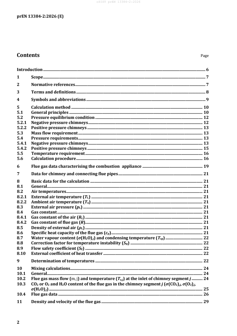
Contents Page
Introduction . 6
1 Scope . 7
2 Normative references . 7
3 Terms and definitions . 8
4 Symbols and abbreviations . 9
5 Calculation method . 10
5.1 General principles . 10
5.2 Pressure equilibrium condition . 12
5.2.1 Negative pressure chimneys . 12
5.2.2 Positive pressure chimneys . 13
5.3 Mass flow requirement . 13
5.4 Pressure requirements . 13
5.4.1 Negative pressure chimneys . 13
5.4.2 Positive pressure chimneys . 15
5.5 Temperature requirement . 16
5.6 Calculation procedure . 16
6 Flue gas data characterising the combustion appliance . 19
7 Data for chimney and connecting flue pipes . 21
8 Basic data for the calculation . 21
8.1 General . 21
8.2 Air temperatures . 21
8.2.1 External air temperature (T ) . 21
L
8.2.2 Ambient air temperature (T ) . 21
u
8.3 External air pressure (p ) . 21
L
8.4 Gas constant . 21
8.4.1 Gas constant of the air (R ) . 21
L
8.4.2 Gas constant of flue gas (R). 21
8.5 Density of external air (ρ ) . 21
L
8.6 Specific heat capacity of the flue gas (c ) . 21
p
8.7 Water vapour content (σ(H O) ) and condensing temperature (T ) . 22
2 ,j sp
8.8 Correction factor for temperature instability (S ) . 22
H
8.9 Flow safety coefficient (S ) . 22
E
8.10 External coefficient of heat transfer . 22
9 Determination of temperatures . 22
10 Mixing calculations . 24
10.1 General . 24
10.2 Flue gas mass flow (m, j) and temperature (T ) at the inlet of chimney segment j . 24
e,j
10.3 CO or O and H O content of the flue gas in the chimney segment j (σ(CO ) , σ(O ) ,
2 2 2 2 ,j 2 ,j
σ(H O) ) . 25
2 ,j
10.4 Flue gas data . 26
11 Density and velocity of the flue gas . 29
prEN 13384-2:2026 (E)
12 Determination of the pressures . 30
12.1 Pressures at each inlet of the chimney segments . 30
12.1.1 Draught . 30
12.1.2 Positive pressure . 30
12.1.3 Draught available due to chimney effect in the chimney segment (P ) . 30
H,j
12.1.4 Pressure resistance in the chimney segment (P ) . 30
R,j
12.2 Minimum draught required at the flue gas inlet into the chimney and maximum allowed
draught (P and P ) and maximum and minimum differential pressure at the flue gas
Ze Zemax
inlet into the chimney (P and P ) . 33
ZOe ZOemin
12.2.1 Minimum required and maximum allowed draught . 33
12.2.2 Maximum available and minimum allowed differential pressure . 33
12.2.3 Calculated pressure resistance of the connecting flue pipe (P ) . 33
V,j
12.2.4 Calculated pressure resistance of the air supply (P ) . 36
Bc,j
13 Inner surface temperature . 37
14 Cascade installations . 37
14.1 Principle of the calculation method . 37
14.2 Pressure equilibrium condition . 38
14.2.1 Negative pressure cascade installation . 38
14.2.2 Positive pressure cascade installation . 39
14.3 Mass flow requirement . 39
14.4 Pressure requirements . 40
14.4.1 Negative pressure chimneys . 40
14.4.2 Positive pressure chimneys . 41
14.5 Temperature requirement . 42
14.6 Calculation procedure . 43
14.7 Pressures at the outlet of the connecting flue pipe and pressures at the inlet of the
collector segment . 43
14.7.1 Pressure at the flue gas inlet into the collector segment (P or P ) . 43
ZC,j,l ZOC,j,l
14.7.2 Pressures required or available at the outlet of the connecting flue pipe (P , P ) 46
ZeC,j,l ZOeC,j,l
14.8 Inner surface temperature (T ) . 48
iobC,j,l
15 Calculation method for balanced flue chimneys . 48
15.1 General principles . 48
15.2 Pressure equilibrium condition . 49
15.3 Mass flow requirement . 49
15.4 Pressure requirements . 49
15.4.1 Negative pressure chimneys . 49
15.4.2 Positive pressure chimneys . 50
15.5 Temperature requirements . 51
15.6 Calculation procedure for balanced flue chimneys . 51
15.7 Mass flow of the combustion air . 53
15.8 Determination of the temperatures in balanced flue chimneys . 54
15.8.1 Non-concentric (separate) ducts. 54
15.8.2 Concentric ducts . 54
15.9 Determination of densities and velocities . 72
15.9.1 Density and velocity of the flue gas . 72
15.9.2 Density and velocity of the combustion air . 72
15.10 Determination of pressures . 74
15.10.1 Pressures in the flue duct segments and connecting flue pipes . 74
15.10.2 Pressures in the air supply duct segments . 74
15.10.3 Pressures in the connecting air supply pipes . 77
15.11 Calculation of the inner surface temperature at the flue duct outlet (T ) . 79
iob
prEN 13384-2:2026 (E)
16 Calculation method for a balanced flue chimney with more than one individual flue
ducts in a collective air supply duct . 79
17 Consideration of chimney fans . 81
17.1 General . 81
17.2 Inline fans . 82
17.3 Exhaust fans . 83
Annex A (informative) Recommendations. 84
Annex B (informative) Characteristics for the combustion appliance . 85
Annex C (informative) Example for a report about input and output data of the calculation . 90
Bibliography. 105
prEN 13384-2:2026 (E)
European foreword
This document (prEN 13384-2:2026) has been prepared by Technical Committee CEN/TC 166
“Chimneys”, the secretariat of which is held by ASI.
This document is currently submitted to the CEN Enquiry.
This document will supersede EN 13384-2:2015+A1:2019.
In comparison to EN 13384-2:2015+A1:2019, the following technical changes have been made:
— editorial mistakes have been corrected;
— the calculation methods were extended to include the O content of the flue gas;
— the pressure requirements for negative pressure chimneys have been modified for a possible
connection of a positive pressure combustion appliance with a total or partly positive pressure
connection pipe;
— remarks have been added for the temperature requirement;
— for concentric duct the simplified heat transfer calculation method based on S has been deleted.
rad
Therefore, the detailed calculation method has been added from part 1;
— a new clause has been created for calculation of a common balanced flue chimney with more than
one flue pipe:
— a clarification is made for the ζ-values of terminals, linked to static pressure;
— a new Annex C “Example for a report about input and output data of the calculation” has been added.
EN 13384, Chimneys — Thermal and fluid dynamic calculation methods consists of three parts:
— Part 1: Chimneys serving one combustion appliance
— Part 2: Chimneys serving more than one combustion appliance
— Part 3: Methods for the development of diagrams and tables for chimneys serving one heating
appliance
prEN 13384-2:2026 (E)
Introduction
The calculation described in this document is complex and is intended to be solved by using a computer
program. The general principles of the calculation method of prEN 13384-1:2025 also apply to this
document.
This document is in support of the execution standards for a chimney installation serving more than one
combustion appliance.
The execution standards in conjunction with installation instructions identify limitations and safety
considerations associated with the design, installation, commissioning and maintenance of a chimney
serving more than one combustion appliance (not dealt within the calculation method).
prEN 13384-2:2026 (E)
1 Scope
This document specifies methods for calculation of the thermal and fluid dynamic characteristics of
chimneys serving more than one combustion appliance.
This part of prEN 13384 covers the following cases:
a) where the chimney is connected with more than one connecting flue pipe from individual or several
combustion appliances in a multi-inlet arrangement;
b) where the chimney is connected with an individual connecting flue pipe connecting more than one
combustion appliance in a cascade arrangement; or
c) where the balanced flue chimney consists of a collective air supply duct serving the combustion air
to more than one combustion appliance. Each combustion appliance is connected to an individual
flue duct located inside the collective air supply duct to the outlet. Every individual flue duct has a
temperature class not exceeding T120, a pressure class of P1, M1 or H1 and a sootfire class of O.
The case of multiple inlet cascade arrangement is covered by the case a).
This part of prEN 13384 deals with chimneys operating under negative pressure conditions (there can
be positive pressure condition in the connecting flue pipe) and with chimneys operating under positive
pressure conditions and is valid for chimneys serving combustion appliances for liquid, gaseous and
solid fuels.
For positive pressure chimneys (case a), b) and c)) this part only applies if any combustion appliance
which is out of action can be positively isolated to prevent flue gas back flow.
This part of EN 13384 does not apply to:
— chimneys with different thermal resistance or different cross-section in the various chimney
segments. This part does not apply to calculate energy gain;
— chimneys with open fire places, e.g. open fire chimneys or chimney inlets which are normally
intended to operate open to the room;
— chimneys which serve different kinds of combustion appliances regarding natural draught, fan
assisted, forced draught or combustion engine. Fan assisted combustion appliances with draught
diverter between the fan and the chimney are considered as natural draught combustion
appliances;
— chimneys with multiple inlets from more than 5 storeys. (This does not apply to balanced flue
chimney.);
— chimneys serving combustion appliances with open air supply through ventilation openings or air
supply ducts, which are not installed in the same air supply pressure region (e.g. same side of
building).
2 Normative references
The following documents are referred to in the text in such a way that some or all of their content
constitutes requirements of this document. For dated references, only the edition cited applies. For
undated references, the latest edition of the referenced document (including any amendments) applies.
EN 1443:2019, Chimneys — General requirements
prEN 13384-2:2026 (E)
prEN 13384-1:2025, Chimneys — Thermal and fluid dynamic calculation methods — Part 1: Chimneys
serving one combustion appliance
EN 15287-1:2023, Chimneys — Design, installation and commissioning — Part 1: Chimneys for non-
roomsealed combustion appliances
EN 15287-2:2023, Chimneys — Design, installation and commissioning — Part 2: Chimneys and
connecting flue pipes for roomsealed combustion appliances
3 Terms and definitions
For the purposes of this document, the terms and definitions given in EN 1443:2019,
prEN 13384-1:2025, EN 15287-1:2023, EN 15287-2:2023 and the following apply.
3.1
chimney segment
part of a chimney between two consecutive flue gas connections or between the last flue gas connection
and the chimney outlet
3.2
collector segment
part of a connecting flue pipe between two consecutive flue gas connections or between the last flue gas
connection and the chimney inlet
3.3
flue gas mass flow
𝒎𝒎̇
mass of the flue gas leaving the combustion appliance through the connecting flue pipe per unit of time
Note 1 to entry: In case of a chimney serving more than one combustion appliance, the air being transported
through a combustion appliance which is out of action is also given the term flue gas mass flow.
3.3.1
declared flue gas mass flow
𝒎𝒎̇
W,j
flue gas mass flow given in the documentation of the combustion appliance j with respect to the heat
output used in the calculation
3.3.2
calculated flue gas mass flow
𝒎𝒎̇
Wc,j
flue gas mass flow calculated with respect to calculated draught and the working conditions of the
combustion appliance j
3.4
calculated flue gas temperature
𝑻𝑻
Wc,j
flue gas temperature at the outlet of the combustion appliance j depending on the calculated flue gas
mass flow
prEN 13384-2:2026 (E)
3.5
calculated draught of the flue gas of the combustion appliance
𝑷𝑷
Wc,j
draught at the flue gas outlet of the combustion appliance j depending on the calculated flue gas mass
flow
3.6
flue damper
device to close or partially close the flue
3.7
balanced flue chimney
chimney where the point of air entry to the air supply duct is adjacent to the point of discharge of
combustion products from the flue, the inlet and outlet being so positioned that wind effects are
substantially balanced
3.8
cascade arrangement
arrangement where two or more combustion appliances situated in the same space are connected by a
common connecting flue pipe to the chimney
3.9
multi inlet arrangement
arrangement where two or more combustion appliances are connected to the chimney by individual
connecting flue pipes
3.10
air supply duct
independent duct in a building or a structural part of a flue terminal conveying combustion air to a room-
sealed combustion appliance
3.11
pressure equalizing opening
opening or duct that directly connects the air supply duct with the flue at its base
4 Symbols and abbreviations
Symbols, terminology and units are given to make the text of this document understandable. A list of
general symbols and abbreviations is given in prEN 13384-1:2025, Clause 4. Indices added to symbols
for purposes of the calculation method for chimneys serving more than one combustion appliance relate
to one chimney segment and connecting flue pipe section. An example of an indices numbering scheme
is given in Figures 1 and 2. Indices numbering begins at the lowest, farthest combustion appliance
connection. For more than one cascade system/connection, the indices numbering scheme for the
calculation formula should be adopted in a similar manner to that for a single cascade scheme. Symbols
assigned to a specific section will be indicated by the number of the section after the comma (e. g. H is
,1
the effective height of a section of a chimney segment between the outlet of the connecting flue pipe of
the combustion appliance in the lowest position and the outlet of the connecting flue pipe of the next
combustion appliance).
Each symbol and abbreviation is explained at the formula where it is used.
prEN 13384-2:2026 (E)
5 Calculation method
5.1 General principles
Key
1 chimney
2 connecting flue pipe j
3 combustion appliance j
4 connecting flue pipe 2
5 combustion appliance 2
6 connecting flue pipe 1
7 combustion appliance 1
8 chimney segment 1
9 chimney segment j
Figure 1 — Example of multiple inlet arrangement and numbering pressure values and
temperature values of a chimney serving more than one combustion appliance
The calculation is based upon determining the mass flow distribution in the chimney which fulfils the
pressure equilibrium condition (Formula (1) or (4)) at each flue gas inlet to the chimney (see Figure 1).
After such a distribution has been found four requirements shall be verified:
a) the mass flow requirement (Formulae (7) and (8));
b) the pressure requirement for minimum draught (Formula (9) and, if appropriate, Formulae (10),
(11), (12) or (13)), or for maximum positive pressure (Formulae (15) and (16));
c) the pressure requirement for maximum draught (Formula (14)) or for minimum positive pressure
(Formula (17));
prEN 13384-2:2026 (E)
d) the temperature requirement (Formula (18)).
NOTE The calculation is affected by the specific installation design. For recommendations for the installation
of combustion appliance and connection flue pipes, see Annex A.
The pressure requirements for maximum draught or minimum positive pressure are only required if
there is a limit for the maximum draught for the negative pressure combustion appliance or a minimum
differential pressure of the positive pressure combustion appliance.
In order to verify the criteria, two sets of external conditions are used:
— the calculation of the minimum draught and maximum positive pressure is made with conditions
for which the capacity of the chimney is minimal (i.e. high outside temperature); and also
— the calculation of the maximum draught and minimum positive pressure and of the inner surface
temperature with conditions for which the inside temperature of the chimney is minimal (i.e. low
outside temperature).
The validation of the mass flow requirement and pressure requirement shall be done at following
working conditions, using the external and ambient air temperatures specified in prEN 13384-1:2025:
— all combustion appliances are simultaneously operating at nominal heat output;
— all combustion appliances are simultaneously operating at minimum heat output;
— a single combustion appliance operating at nominal heat output and all other combustion
appliances out of action (all possible cases);
— a single combustion appliance operating at minimum heat output and all other combustion
appliances out of action (all possible cases);
— for positive pressure chimneys a single combustion appliance operating at minimum nominal heat
output and all other combustion appliances operating at maximum nominal heat output (all
possible cases).
If the control of the installation guarantees that not all combustion appliances will be in operation
simultaneously, the validation of the mass flow requirement and pressure requirement may be done
with the maximum number of combustion appliances which will be in operation under the most adverse
condition.
The validation for the mass flow requirement and pressure requirement for working conditions with
combustion appliances at minimum heat output is not required in the following cases:
— the combustion appliances do not have any heat output range;
— the combustion appliances have a heat output which is limited to a fixed value as specified on a
label on the combustion appliance. In this case the nominal heat output is the given heat output on
the label;
— combustion appliances heated with solid fuels without fan and combustion appliances with
regulated air supply.
The validation of the mass flow requirement for working conditions with combustion appliances at
nominal heat output is not required in the following case:
— the combustion appliances have a flue gas mass flow at minimum heat output higher than or equal
to the flue gas mass flow at nominal heat output.
prEN 13384-2:2026 (E)
The temperature requirement shall be validated for the following relevant working condition, using the
ambient and external air temperatures as specified in prEN 13384-1:2025:
— combustion appliances for solid fuels without fan and combustion appliances with regulated air
supply are in operation at nominal heat output;
— combustion appliances with a draught diverter which provide domestic hot water only are out of
action. These combustion appliances operate with a considerable secondary air (these operate only
a short time and therefore it can be assumed that condensation will not cause damage or a lack in
safety);
— combustion appliances with a fixed output range are in operation at this (nominal) heat output;
— all other combustion appliances are in operation at minimum heat output.
When chimneys suitable for operating under wet conditions are located inside a building, the check of
the temperature requirement is necessary only for the top of the chimney.
The validation of the temperature requirement is not necessary when the chimney serves only domestic
gas fired water heaters with instantaneous production and domestic gas fired storage water heaters.
If the chimney system includes a draught regulator, the system is handled as a cascade system.
The input data and results of the calculation shall be reported. An example of the content is given in
Annex C.
5.2 Pressure equilibrium condition
5.2.1 Negative pressure chimneys
The following formulae shall be fulfilled for each chimney segment j at all relevant working conditions:
�𝑃𝑃 −𝑃𝑃 �≤ 0,1, in Pa (1)
𝑍𝑍,𝑗𝑗 Ze,𝑗𝑗
𝑁𝑁
𝑃𝑃 =−𝑃𝑃 +� �𝑃𝑃 −𝑃𝑃 � , in Pa (2)
Z,𝑗𝑗 𝐿𝐿 H,k R,k
𝑘𝑘=𝑗𝑗
𝑃𝑃 =𝑃𝑃 +𝑃𝑃 +𝑃𝑃 , in Pa (3)
Ze,j Wc,j V,j Bc,j
where
P is the draught at the flue gas inlet to the chimney segment j, in Pa;
Z,j
P is the theoretical draught available due to chimney effect in chimney segment k, in Pa;
H,k
P is the pressure resistance of the chimney segment k, in Pa;
R,k
P is the calculated draught of the combustion appliance, in Pa;
Wc,j
P is the calculated pressure resistance of the connecting flue pipe j, in Pa;
V,j
P is the calculated pressure resistance of the air supply for the combustion appliance j, in Pa;
Bc,j
P is the required draught at the flue gas inlet to the chimney segment j, in Pa;
Ze,j
P is the wind velocity pressure, in Pa;
L
N is the number of combustion appliances.
prEN 13384-2:2026 (E)
5.2.2 Positive pressure chimneys
The following formulae shall be fulfilled for each chimney segment j at all relevant working conditions:
�𝑃𝑃 −𝑃𝑃 �≤ 0,1 , in Pa (4)
ZOe,𝑗𝑗 ZO,𝑗𝑗
𝑁𝑁
𝑃𝑃 =𝑃𝑃 +� 𝑃𝑃 −𝑃𝑃 , in Pa (5)
� �
Z,O𝑗𝑗 𝐿𝐿 R,k H,k
𝑘𝑘=𝑗𝑗
𝑃𝑃 =𝑃𝑃 −𝑃𝑃 −𝑃𝑃 , in Pa (6)
ZOe,𝑗𝑗 WOc,j V,j Bc,j
where
P is the positive pressure at the flue gas inlet to the chimney segment j, in Pa;
ZO,j
P is the theoretical draught available due to chimney effect in chimney segment k, in Pa;
H,k
P is the pressure resistance of the chimney segment k, in Pa;
R,k
P is the calculated positive differential pressure of the combustion appliance j, in Pa;
WOc,j
P is the calculated pressure resistance of the connecting flue pipe j, in Pa;
Vj
P is the calculated pressure resistance of the air supply for the combustion appliance j, in Pa;
Bc,j
P is the maximum differential pressure at the flue gas inlet to the chimney segment j, in Pa;
ZOe,j
P is the wind velocity pressure;
L
N is the number of combustion appliances.
5.3 Mass flow requirement
Formulae (7) and (8) shall be verified for all relevant working conditions (see 5.6).
For each combustion appliance in operation at nominal or minimum heat output:
𝑚𝑚̇≥𝑚𝑚̇, in kg/s (7)
Wc,j W,j
and for each combustion appliance out of action:
𝑚𝑚̇≥ 0, in kg/s (8)
Wc,j
where
𝑚𝑚̇ is the calculated mass flow of the combustion appliance, in kg/s;
Wc,j
𝑚𝑚̇ is the declared mass flow of the combustion appliance, in kg/s.
W,j
Where a totally closed mechanically driven flue damper (Type 2 in accordance with EN 16475-4) is
applied, mass flow of a combustion appliance out of action shall be taken as 0. Otherwise as flow
resistance for a flue damper of a combustion appliance out of action shall be taken as 0 unless additional
data are available.
5.4 Pressure requirements
5.4.1 Negative pressure chimneys
For negative pressure chimneys, it has to be additionally checked that the minimum draught (negative
pressure) in the chimney (P ) is more than or equal to the negative pressure in the room where the
Z,j
combustion appliance is placed at calculated draught conditions for air supply. The check on this
prEN 13384-2:2026 (E)
pressure requirement shall be done using the same conditions as specified for the check on the mass
flow requirement (see 5.3 and 5.6). The following relationships shall be verified:
𝑃𝑃 ≥𝑃𝑃 , in Pa (9)
Z,j Bc,j
and if P < 0 Pa and the connecting flue pipe j is designated for negative pressure (N):
W,j
P ≥ P + P , in Pa (10)
Z,j Bc,j V,j
or if P < 0 Pa and the connecting flue pipe j is designated for positive pressure (P, M or H):
W,j
P – P ≤ P , in Pa (11)
V,j Z,j ZVexcess, j
or if P < 0 Pa and only the first part of the connecting flue pipe j is designated for positive pressure:
W,j
P ≥ P + P , in Pa (12)
Z,j Bc,j V2,j
P + P – P ≤ P , in Pa (13)
V1,j V2,j Z,j ZVexcess,j
where
P is the draught at the inlet to the chimney segment j, in Pa;
Z,j
P is the calculated pressure resistance of the air supply for the combustion appliance j, in Pa;
Bc,j
P is the minimum draught for the combustion appliance j, in Pa;
W,j
P is the calculated pressure resistance of the connecting flue pipe j, in Pa;
V,j
P is the calculated pressure resistance of a first, positive pressure part of the connecting flue
V1,j
pipe j, in Pa;
P is the calculated pressure resistance of a second, negative pressure part of the connecting
V2,j
flue pipe j, in Pa;
P is the maximum allowed pressure from the designation of the connecting flue pipe j, in Pa.
ZVexcess,j
If required, it has to be additionally checked that the draught in the chimney (P ) is less than or equal
Zmax,j
to the maximum allowed draught (P ) caused by the combustion appliance. The Formula (14) shall
Zemax,j
be verified for all relevant working conditions (see 5.6). The check of this pressure requirement shall be
done with a separate calculation using the newly calculated flue mass flows that fulfil the pressure
equilibrium conditions at an external air temperature of T = 258,15 K (t = -15 °C, see prEN 13384-
L L
1:2025, 5.7.1.2).
𝑁𝑁
𝑃𝑃 =� �𝑃𝑃 −𝑃𝑃 � ≤𝑃𝑃 +𝑃𝑃 +𝑃𝑃 =𝑃𝑃 , in Pa (14)
Zmax,𝑗𝑗 H,k R,k Wmax,j V,j Bc,j Zemax,j
𝑘𝑘=𝑗𝑗
where
PZmax,j is the maximum draught at the flue gas inlet into the chimney segment j, in Pa;
P is the maximum allowed draught at the flue gas inlet into the chimney segment j, in
Zemax,j
Pa;
P is the theoretical draught available due to chimney effect in chimney segment k, in
H,k
Pa;
P is the pressure resistance of the chimney segment k, in Pa;
R,k
prEN 13384-2:2026 (E)
P is the maximum draught for the combustion appliance j, in Pa;
Wmax,j
P is the calculated pressure resistance of the connecting flue pipe j, in Pa;
V,j
P is the calculated pressure resistance of the air supply for the combustion appliance j,
Bc,j
in Pa.
NOTE The values of PH,k, PR,k, PV,j and PBc,j in Formulae (2) and (14) are normally different because the
conditions are different.
5.4.2 Positive pressure chimneys
For positive pressure chimneys it has to be additionally checked that the maximum positive pressure in
the connecting flue pipe (P + P ) and in the chimney (P ) is not higher than the excess pressure for
ZO,j V,j ZO,j
which both are designated (PZVexcess and PZexcess). The check on the pressure requirement shall be done
using the same conditions as specified for the check on the mass flow requirement (see 5.3 and 5.6). The
following relationships shall be verified:
P ≤ P , in Pa (15)
ZO,j Zexcess
P + P ≤ P , in Pa (16)
ZO,j V,j ZVexcess
where
P is the positive pressure at the flue gas inlet to the chimney segment j, in Pa;
ZO,j
P is the calculated pressure resistance of the connecting flue pipe j, in Pa;
V,j
P is the maximum allowed pressure from the designation of the chimney, in Pa;
Zexcess
P is the maximum allowed pressure from the designation of the connecting flue pipe, in Pa.
ZVexcess
If required, it has to be additionally checked that the minimum positive pressure in the chimney (PZOmin,j)
is more than or equal to the minimum allowed positive pressure (P ) caused by the combustion
ZOemin,j
appliance. The relationship (17) shall be verified for all relevant working conditions (see 5.6).
The check of this pressure requirement shall be done with a separate calculation using the newly
calculated flue mass flows that fulfil the pressure equilibrium conditions at an external air temperature
of T = 258,15 K (t = -15 °C, see prEN 13384-1, 5.7.1.2).
L L
𝑁𝑁
𝑃𝑃 =� 𝑃𝑃 −𝑃𝑃 ≥𝑃𝑃 −𝑃𝑃 −𝑃𝑃 =𝑃𝑃 , in Pa (17)
� �
ZOmin,j R,k H,k WOmin,j Bc,j FV,j ZOemin , j
𝑘𝑘=𝑗𝑗
where
P is the minimum positive pressure at the flue gas inlet into the chimney segment j, in Pa;
ZOmin,j
P is the minimum differential pressure at the flue gas inlet into the chimney segment j, in Pa;
ZOemin,j
P is the theoretical draught available due to chimney effect in chimney segment k, in Pa;
H,k
P is the pressure resistance of the chimney segment k, in Pa;
R,k
P is the minimum differential pressure of the combustion appliance j, in Pa;
WOmin,j
P is the calculated pressure resistance of the air supply for the combustion appliance j, in Pa;
Bc,j
P is the calculated pressure resistance of the connecting flue pipe j, in Pa.
V,j
NOTE The values of PH,k and PR,k in Formulae (5) and (17) are normally different because the conditions are
different.
prEN 13384-2:2026 (E)
5.5 Temperature requirement
The relationship (18) shall be verified for all relevant working conditions (see 5.6).
The check of the temperature requirement shall be done with a separate calculation using the newly
calculated flue mass flows that fulfil the pressure equilibrium conditions at an external air temperature
of T (see prEN 13384-1, 5.7.1.3)
uo,j
T ≥ T , in K (18)
iob,j g,j
where
T is the temperature of the inner surface of the chimney segment j at the outlet, in K;
iob,j
T is the temperature limit for chimney segment j, in K.
g,j
The temperature limit T for chimneys suitable for operating under dry conditions is equal to the
g,j
condensing temperature T of the flue gas (see 8.7): T = T .
sp,j g,j sp,j
The temperature limit T for chimneys suitable for operating under wet conditions is equal to the
g,j
freezing point of water: Tg,j = 273,15 K.
Particularly when replacing a combustion appliance, compliance with the temperature rquirement can
be waived in specific individual cases if the fire and operational safety of the system is not restricted.
This can be assumed e.g. if:
after replacing non-condensing combustion appliances by similar kinds of combustion appliances
connected to an existing chimney for dry operation conditions, there is a risk of moistering if no
adjustment of the cross-section takes place;
roomsealed combustion appliances connected to an existing chimney for wet operating conditions
shut down automatically before freezing which leads to blockage of the flue;
in the case that the calculation for the lowest permissible heat output is carried out with higher
values for the combustion air mass flow or for the flue gas temperature than specified in Clause 6.
In these situations, a written agreement shall be settled separately between the owners of the
installation and the installer, including advice about possible consequences.
5.6 Calculation procedure
For the calculation of the pressure and temperature values in a chimney serving more t
...