

CEN/TS 115-4:2026
(Main)Safety of escalators and moving walks - Part 4: Interpretations related to EN 115 family of standards
- Abstract
This document is a collection of interpretations related to the EN 115 series. This document collects interpretations to EN 115-1:2008+A1:2010 and EN 115-1:2017. Interpretations to other standards of the EN 115 series will be added when they are available.
Interpretations aim to improve the understanding of the clause(s) they are referring to and by that facilitating common understanding between manufacturers, installers, notified bodies, inspection bodies and national authorities.
Interpretations do not have the same status as the European standards to which they are related. However, the application of interpretations given to the interested parties confidence that the relevant European standard has not been wrongly applied.
- Status
- Published
- Publication Date
- 28-Apr-2026
- Technical Committee
- CEN/TC 10 - Passenger, goods and service lifts
- Drafting Committee
- CEN/TC 10/WG 2 - Escalators and passenger conveyors
- Current Stage
- 6060 - Definitive text made available (DAV) - Publishing
- Start Date
- 29-Apr-2026
- Due Date
- 10-Feb-2027
- Completion Date
- 29-Apr-2026

CEN/TS 115-4:2026 is a CEN Technical Specification for the EN 115 family on safety of escalators and moving walks. It gathers interpretations for EN 115-1:2008+A1:2010 and EN 115-1:2017 to help manufacturers, installers, notified bodies, inspection bodies and national authorities read the clauses in the same way. The document explains how the EN 115-1 provisions are understood in practice; it is not the same as the European standards it interprets.
What does CEN/TS 115-4:2026 specify?
CEN/TS 115-4:2026 specifies a collection of interpretations related to the EN 115 series, with the present collection focused on EN 115-1. It is organized as a short front section, a list of normative references, a clause-by-clause list of interpretations in Clause 3, and the detailed interpretation texts in Clause 4.
Clause 3 presents the interpretations in two ways - by interpretation number and by EN 115-1 clause or subclause. Clause 4 then gives the full question-and-answer style text for each interpretation.
The document also makes clear that interpretations are meant to improve understanding and common application, but they do not have the same status as the European standards they refer to. In practice, that matters when a project team needs to justify a design choice, an inspection result, or a reading of a clause that has caused disagreement.
What are the key requirements of CEN/TS 115-4:2026?
CEN/TS 115-4:2026 does not add a new design code of its own. Instead, its key content is the practical interpretation of EN 115-1 clauses that affect design, installation, inspection and building interfaces.
Application status and intended use
The document states that interpretations are a practical way to answer clause questions, feed user experience back to the responsible committee, and guide later development of the EN 115 family. It also says that applying the interpretations gives confidence that the related European standard has not been wrongly applied. For users, this means the text is meant to reduce ambiguity in real projects, not to replace EN 115-1.
Starting, stopping and braking
Several interpretations clarify how the control system should behave. For example, automatic start in two-direction mode is permitted only for escalators, not moving walks, and the direction and mode must be clearly visible to the user. Another interpretation says that starting switches require the operator to ensure that no user or object is on the step/pallet band before start.
The braking interpretations are especially important in practice. Electrical braking with inverter can be treated as “other means” for operational braking when it is combined with an auxiliary brake and with monitoring for excessive speed and unintended reversal. The text also explains that the braking sequence has to begin immediately, so the control logic cannot introduce an intentional delay.
Structural, durability and measurement points
The document clarifies how to read the requirements for step and pallet geometry, gaps, grooves and wear-related checks. It covers the measurement of the clearance between consecutive steps or pallets, the groove width and web width in the tread, and the way these dimensions are measured when edges are rounded. It also addresses nominal infinite fatigue life for driving elements and step/pallet chains, which matters for durability verification and design documentation.
The interpretations also touch on fire reaction and friction-related checks. For steps and pallets, the fire classification requirement is linked to EN 13501-1, and the interpretations explain how surface inserts are treated. For anti-slip properties, the document points readers to the way surface profiles and walking direction are assessed.
Landings, unrestricted areas and fixed devices
Several interpretations focus on the spaces around escalators and moving walks. The unrestricted area at landings must remain flat, with only a small permissible inclination, and fixed stairs are not allowed in that area. Where fixed devices such as guiding barriers or traffic columns are placed in the unrestricted area, the interpretations describe placement rules, safety-distance checks and how the area may be extended.
This matters because many design problems arise at the interface with the building, not inside the escalator itself. The document also clarifies additional stop switches at handrail level, handrail clearances, and the handling of fixed balustrade arrangements in hazardous areas.
Shopping trolleys, baggage carts and user access
Annex I interpretations explain when barriers are needed to prevent shopping trolleys and baggage carts from entering the installation. The text says the need depends on whether it is reasonably foreseeable that trolleys can be taken onto the escalator or moving walk. It also gives practical constraints on barrier location, size, load resistance and monitoring when the installation works in both directions.
Annex G is interpreted for access by guide dogs for blind people. The document confirms that escalators and moving walks are for transporting persons only, and that if a lift is available it is the preferred method of vertical travel for people with guide dogs.
Seismic design
Annex M is treated as a major technical topic in this document. The interpretations explain how seismic parameters are to be obtained, how the customer and supplier divide responsibilities, and how Annex M relates to EN 1998-1. They also clarify structural retention, support overlap, uplift checks, and post-event inspection after a seismic event of sufficient intensity.
For projects in seismic regions, this section is important because it ties escalator and moving walk design to the building’s seismic behavior and to the interface between machine supports and the structure.
What terms does CEN/TS 115-4:2026 define?
- Nominal speed - The speed stated by the manufacturer for which the escalator or moving walk is designed.
- Unrestricted area - The landing area around the installation that is kept clear for safe passenger movement and for building-interface conditions.
- Auxiliary braking system - A brake system used to stop and hold the escalator or moving walk when the operational brake is not used in the usual way.
- Failure lock - A safety function that prevents certain unsafe restarting or operating conditions after a detected failure.
- Inter storey drift - The relative movement between building storeys used in Annex M to check the interface between the building and the escalator or moving walk.
- Nominal infinite fatigue life - A design intent that the part is treated as having fatigue resistance suitable for very long-term service under the specified design loading.
- Guide dogs - Dogs used by blind people, addressed in Annex G as part of the access and user-signage topic.
Who uses CEN/TS 115-4:2026?
CEN/TS 115-4:2026 is used by manufacturers and installers who need to design and place components in line with EN 115-1 interpretations. It is also used by notified bodies, inspection bodies and national authorities when checking whether an installation has been assessed consistently.
In practice, it helps engineers, quality managers and project buyers working on escalators and moving walks. The main tasks are design review, conformity assessment, inspection planning, building-interface coordination and documentation of braking, guarding, access and seismic behavior.
What changed in CEN/TS 115-4:2026 from the previous edition?
CEN/TS 115-4:2026 supersedes CEN/TS 115-4:2020. The European foreword states that interpretations 151 to 158 are added in this edition.
Those added interpretations cover failure lock in inspection mode, the stop device reference in inspection control, accessibility to guide dogs, nominal infinite fatigue life, fixed balustrade in the hazardous area, inspection and tests, shopping trolley width and skirt deflector, and groove width and web width.
Which standards are used with CEN/TS 115-4:2026?
| Standard | What it contributes |
|---|---|
| EN 115-1:2008+A1:2010 | One of the main EN 115-1 editions interpreted by this Technical Specification |
| EN 115-1:2017 | The other main EN 115-1 edition interpreted by this Technical Specification |
| EN 115-2 | Named in the EN 115 family overview as the part for improving the safety of existing escalators and moving walks |
| CEN/TR 115-3 | Named in the EN 115 family overview as the correlation between EN 115-1:2008+A1:2010 and EN 115-1:2017 |
| EN 1991-1-1 | Used in interpretations for structural actions on fixed devices and barriers |
| EN 1993-1-1:2005 | Used for steel structure design in seismic and support-related interpretations |
| EN 1998-1:2004 | The seismic design basis used in Annex M interpretations |
| EN 1990:2002+A1:2005 | Cited in the seismic interpretations for action combinations and seismic design situations |
| EN 13501-1:2007+A1:2009 | Used for fire classification of steps and pallets |
| EN 13823 | Used in the fire test discussion for reaction-to-fire assessment |
| EN 1929-1 | Used as the basis for the shopping trolley impact conditions in barrier interpretations |
| EN ISO 13857:2019 | Cited for safety distances to prevent reaching hazard zones |
| EN ISO 13854 | Cited in the bibliography for minimum gaps to avoid crushing of parts of the human body |
What does the CEN/TS 115-4:2026 document contain?
CEN/TS 115-4:2026 contains a foreword, an introduction, the scope, normative references, a structured list of interpretations, and the detailed interpretation texts. Clause 3 provides two tables that index the interpretations by number and by EN 115-1 clause or subclause.
Clause 4 contains the full interpretation texts, many of which address dimensions, gaps, braking behavior, barriers, access control, fire reaction, inspection control and seismic design. The document also includes figures and table references inside the interpretation texts, so users can trace how each clarification relates to the original EN 115-1 requirement.
The bibliography points to related standards that support the interpretations, including structural design, fire testing and safety-distance documents.
Relations
- Effective Date
- 02-Jul-2025
- Effective Date
- 07-Oct-2026
Get Certified
Connect with accredited certification bodies for this standard

DIBt (Deutsches Institut für Bautechnik)
German Institute for Building Technology.
DIN CERTCO
DIN Group product certification.

Aboma Certification B.V.
Specialized in construction, metal, and transport sectors.
Sponsored listings
Frequently Asked Questions
CEN/TS 115-4:2026 is a technical specification published by the European Committee for Standardization (CEN). Its full title is "Safety of escalators and moving walks - Part 4: Interpretations related to EN 115 family of standards". This standard covers: This document is a collection of interpretations related to the EN 115 series. This document collects interpretations to EN 115-1:2008+A1:2010 and EN 115-1:2017. Interpretations to other standards of the EN 115 series will be added when they are available. Interpretations aim to improve the understanding of the clause(s) they are referring to and by that facilitating common understanding between manufacturers, installers, notified bodies, inspection bodies and national authorities. Interpretations do not have the same status as the European standards to which they are related. However, the application of interpretations given to the interested parties confidence that the relevant European standard has not been wrongly applied.
This document is a collection of interpretations related to the EN 115 series. This document collects interpretations to EN 115-1:2008+A1:2010 and EN 115-1:2017. Interpretations to other standards of the EN 115 series will be added when they are available. Interpretations aim to improve the understanding of the clause(s) they are referring to and by that facilitating common understanding between manufacturers, installers, notified bodies, inspection bodies and national authorities. Interpretations do not have the same status as the European standards to which they are related. However, the application of interpretations given to the interested parties confidence that the relevant European standard has not been wrongly applied.
CEN/TS 115-4:2026 is classified under the following ICS (International Classification for Standards) categories: 91.140.90 - Lifts. Escalators. The ICS classification helps identify the subject area and facilitates finding related standards.
CEN/TS 115-4:2026 has the following relationships with other standards: It is inter standard links to CEN/TS 115-4:2020, EN 1991-1-1:2025. Understanding these relationships helps ensure you are using the most current and applicable version of the standard.
CEN/TS 115-4:2026 is available in PDF format for immediate download after purchase. The document can be added to your cart and obtained through the secure checkout process. Digital delivery ensures instant access to the complete standard document.
Standards Content (Sample)
SLOVENSKI STANDARD
01-oktober-2026
Varnost tekočih stopnic in tekočih stez - 4. del: Pojasnila v zvezi s skupino
standardov EN 115
Safety of escalators and moving walks - Part 4: Interpretations related to EN 115 family
of standards
Sicherheit von Fahrtreppen und Fahrsteigen - Teil 4: Auslegungen zur Normenreihe EN
Sécurité des escaliers mécaniques et trottoirs roulants - Partie 4 : Interprétations
relatives aux normes de la famille EN 115
Ta slovenski standard je istoveten z: CEN/TS 115-4:2026
ICS:
91.140.90 Dvigala. Tekoče stopnice Lifts. Escalators
2003-01.Slovenski inštitut za standardizacijo. Razmnoževanje celote ali delov tega standarda ni dovoljeno.
CEN/TS 115-4
TECHNICAL SPECIFICATION
SPÉCIFICATION TECHNIQUE
April 2026
TECHNISCHE SPEZIFIKATION
ICS 91.140.90 Supersedes CEN/TS 115-4:2020
English Version
Safety of escalators and moving walks - Part 4:
Interpretations related to EN 115 family of standards
Sécurité des escaliers mécaniques et trottoirs roulants Sicherheit von Fahrtreppen und Fahrsteigen - Teil 4:
- Partie 4 : Interprétations relatives aux normes de la Auslegungen zur Normenreihe EN 115
famille EN 115
This Technical Specification (CEN/TS) was approved by CEN on 20 March 2026 for provisional application.
The period of validity of this CEN/TS is limited initially to three years. After two years the members of CEN will be requested to
submit their comments, particularly on the question whether the CEN/TS can be converted into a European Standard.
CEN members are required to announce the existence of this CEN/TS in the same way as for an EN and to make the CEN/TS
available promptly at national level in an appropriate form. It is permissible to keep conflicting national standards in force (in
parallel to the CEN/TS) until the final decision about the possible conversion of the CEN/TS into an EN is reached.
CEN members are the national standards bodies of Austria, Belgium, Bulgaria, Croatia, Cyprus, Czech Republic, Denmark, Estonia,
Finland, France, Germany, Greece, Hungary, Iceland, Ireland, Italy, Latvia, Lithuania, Luxembourg, Malta, Netherlands, Norway,
Poland, Portugal, Republic of North Macedonia, Romania, Serbia, Slovakia, Slovenia, Spain, Sweden, Switzerland, Türkiye and
United Kingdom.
EUROPEAN COMMITTEE FOR STANDARDIZATION
COMITÉ EUROPÉEN DE NORMALISATION
EUROPÄISCHES KOMITEE FÜR NORMUNG
CEN-CENELEC Management Centre: Rue de la Science 23, B-1040 Brussels
© 2026 CEN All rights of exploitation in any form and by any means reserved Ref. No. CEN/TS 115-4:2026 E
worldwide for CEN national Members.
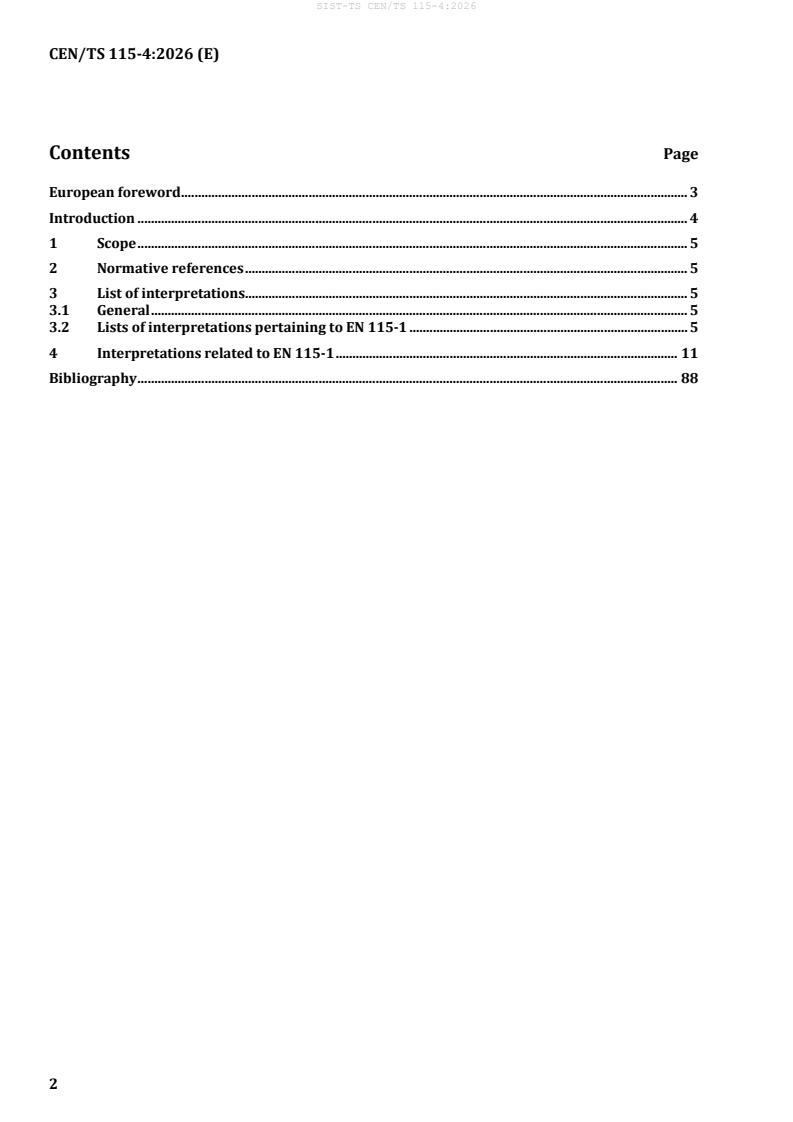
Contents Page
European foreword . 3
Introduction . 4
1 Scope . 5
2 Normative references . 5
3 List of interpretations. 5
3.1 General . 5
3.2 Lists of interpretations pertaining to EN 115-1 . 5
4 Interpretations related to EN 115-1 . 11
Bibliography . 88
European foreword
This document (CEN/TS 115-4:2026) has been prepared by Technical Committee CEN/TC 10 “Lifts,
escalators and moving walks”, the secretariat of which is held by AFNOR.
Attention is drawn to the possibility that some of the elements of this document may be the subject of
patent rights. CEN shall not be held responsible for identifying any or all such patent rights.
This document supersedes CEN/TS 115-4:2020.
Interpretations 151 till 158 are added in this edition compared to CEN/TS 115-4:2020.
EN 115 is divided into the following parts:
— EN 115-1, Safety of escalators and moving walks — Part 1: Construction and installation;
— EN 115-2, Safety of escalators and moving walks — Part 2: Rules for the improvement of safety of
existing escalators and moving walks;
— CEN/TR 115-3, Safety of escalators and moving walks — Part 3: Correlation between EN 115-
1:2008+A1:2010 and EN 115-1:2017 [Technical Report];
— CEN/TS 115-4, Safety of escalators and moving walks - Part 4: Interpretations related to EN 115 family
of standards [Technical specification; the present document].
This document is a collection of interpretations related to the EN 115 series. For the time being, this
collection of interpretations relates to EN 115-1. According to the progress in working out
interpretations, this document will be amended and/or completed.
Any feedback and questions on this document should be directed to the users’ national standards body.
A complete listing of these bodies can be found on the CEN website.
According to the CEN/CENELEC Internal Regulations, the national standards organisations of the
following countries are bound to announce this Technical Specification: Austria, Belgium, Bulgaria,
Croatia, Cyprus, Czech Republic, Denmark, Estonia, Finland, France, Germany, Greece, Hungary, Iceland,
Ireland, Italy, Latvia, Lithuania, Luxembourg, Malta, Netherlands, Norway, Poland, Portugal, Republic of
North Macedonia, Romania, Serbia, Slovakia, Slovenia, Spain, Sweden, Switzerland, Türkiye and the
United Kingdom.
Introduction
Standards reflect the consensus of the best European expertise and are prepared with highest care.
Product standards cannot be formulated in such a way that they describe all possible technical solutions
and therefore exclude all uncertainties regarding the understanding of the required provisions. On the
other hand, technology is in a permanent evolution, the progress of which cannot be incorporated into
standards quickly enough.
Interpretations are a practical way to give:
a) answers to questions regarding the understanding of clauses in standards;
b) feedback to the CEN-Committee responsible for a standard about the practical experiences resulting
from the use of the standard;
c) guidance to further development and improvement of standards following:
1) experience, especially accidents and incidents;
2) progress in technology;
3) state of the art.
1 Scope
This document is a collection of interpretations related to the EN 115 series. This document collects
interpretations to EN 115-1:2008+A1:2010 and EN 115-1:2017. Interpretations to other standards of the
EN 115 series will be added when they are available.
Interpretations aim to improve the understanding of the clause(s) they are referring to and by that
facilitating common understanding between manufacturers, installers, notified bodies, inspection bodies
and national authorities.
Interpretations do not have the same status as the European standards to which they are related.
However, the application of interpretations given to the interested parties confidence that the relevant
European standard has not been wrongly applied.
2 Normative references
The following documents are referred to in the text in such a way that some or all of their content
constitutes requirements of this document. For dated references, only the edition cited applies. For
undated references, the latest edition of the referenced document (including any amendments) applies.
EN 1991-1-1, Eurocode 1: Actions on structures — Part 1-1: General actions — Densities, self-weight,
imposed loads for buildings
EN 1993-1-1:2005, Eurocode 3: Design of steel structures — Part 1-1: General rules and rules for buildings
EN 1998-1:2004, Eurocode 8: Design of structures for earthquake resistance — Part 1: General rules,
seismic actions and rules for buildings
EN 13501-1:2007+A1:2009, Fire classification of construction products and building elements — Part 1:
Classification using data from reaction to fire tests
3 List of interpretations
3.1 General
The following lists show the valid interpretations contained in this document.
3.2 Lists of interpretations pertaining to EN 115-1
The interpretations related to EN 115-1 are listed in Tables 1 and 2.
Table 1 shows the list of interpretations in their numerical order.
Table 2 shows the list of interpretations in order of the clauses of EN 115-1:2008+A1:2010 and
EN 115-1:2017.
These interpretations are detailed in Clause 4.
Table 1 — List of interpretations in numerical order
Interpretation Related clause/ Date of
Keywords
number subclause validity
101 5.3.1 2012–03–14 Increased height of the web on step treads side
102 5.5.2.4, 5.5.3.3 2012–03–14 Form of 25 cm area
103 5.5.3.3 2012–03–14 Load on skirting
104 5.12.2.1.3, 5.12.2.2.2 2012–03–14 Automatic restart in two-direction mode
105 A.2.1 2012–03–14 Unrestricted area, fixed stairs, building height
106 5.12.2.5 2012–03–14 Number of inspection control on site
107 A.2.4 2012–03–14 Rigid deflectors
Barrier to prevent access of shopping trolleys and
108 I.1 2012–03–14
baggage carts
109 5.4.3.2 2012–03–14 Testing of steps and pallets drive
110 5.2.1.2 2012–03–14 Stiffness of exterior panel
111 5.12.2.2.4.1 Table 6 h) 2012–03–14 Stopping of succeeding escalators
112 5.3.5 2012–03–14 Measurement of step to step gap
113 5.9 2012–03–14 Fire protection of steps and pallets
114 5.6.2.1 2012–03–14 Handrail clearances
115 A.2.5 2012–03–14 Unrestricted area at the exit
5.12.2.2.4.1 Table 6 h),
116 2012–03–14 Area of exit
A.2.5
Additional stop switch at handrail level - Building
117 A.2.5, I.2 2012–03–14
interfaces to escalator/moving walk
118 5.8.2.1, A.3.5 2012–03–14 Standing area in machinery spaces
119 A.2 2012–03–14 Fixed devices in unrestricted areas
120 Annex I 2012–03–14 Barriers to prevent shopping trolleys access
121 5.4.2.2.2 2014–11–14 Auxiliary braking system
122 5.3.6 2014–11–14 Location detection missing step device
5.4.2.1.1.1, 5.4.2.1.1.3,
123 2014–11–14 Electrical braking with inverter
5.12.1.2.1.1
124 5.4.1.3.2 2014–11–14 Safety factor of driving elements
- 2 horizontal steps ≤ 6 m vs.
3 horizontal steps > 6 m;
125 4.9, 5.7.2.1 2014–11–14
- Lower escalator transition curve, exit/entry
126 5.3.3.2.2 2014–11–14 Step riser, inserts
127 5.7.3.2.6 2014–11–14 Comb switch
128 5.12.2.1.1 2014–11–14 Starting with passengers on the step/pallet band
129 5.12.2.1.3 2014–11–14 Automatic initiation of starting
130 5.7.2.1 2014–11–14 Landing, vertical difference, consecutive steps
Interpretation Related clause/ Date of
Keywords
number subclause validity
131 5.5.3.4 d), Annex K 2014–11–14 Friction coefficient, material
Measure b
132 A.2.2 2014–11–14
133 5.5.3.4 2014–11–14 Skirt deflector
134 3.1.19, 5.4.1.2 2014–11–14 Definition of nominal speed
135 5.4.2.3 2014–11–14 Excessive speed
136 A.2.5 2014–11–14 Unrestricted area
137 A.2.5 2014–11–14 Unrestricted area
138 5.3.5 2019-09-30 Clearance between two consecutive steps
139 J.2 2019-09-30 Testing and assessing anti-slip properties
140 5.3.3.3.1/5.3.3.3.2 2019-09-30 Step / pallet test frequency
141 5.5.2.1 2019-09-30 Vertical height of the balustrade
142 5.12.3 (EN 115-1:2017) 2019-09-30 Stop device – Disconnection of the power supply
5.4.3.2 and 6 2019-09-30
143 Step/pallet chain – nominal infinite fatigue life
(EN 115-1:2017)
2019-09-30
Auxiliary braking system / verification according
144 5.4.2.2.2 (EN 115-1:2017)
Table 11
5.1 and Annex M 2019-09-30 Seismic – requirements for Escalators / Moving
(EN 115-1:2017) walks vs. Building
2019-09-30 Seismic – requirements for Escalators / Moving
146 Annex M (EN 115-1:2017)
walks vs. Building
2019-09-30 Seismic – requirements for Escalators / Moving
147 Annex M (EN 115-1:2017)
walks vs. Building
2019-09-30 Seismic – requirements for Escalators / Moving
148 Annex M (EN 115-1:2017)
walks vs. Building
149 Annex M (EN 115-1:2017) 2019-09-30 Loading during a seismic event
Annex M, M.2.2 – M.2.4 2019-09-30
150 Structural requirements for seismic conditions
(EN 115-1:2017)
151 5.12.2.8 2020-07-10 Failure lock, Enabled in inspection mode
152 5.12.3.2 2020-10-16 Stop device in reach of the starting devices
Accessibility of escalators and moving walks to
2020-11-27
153 Annex G
guide dogs for blind people
154 5.4.1.3.2, 5.4.3.2 2021-09-10 Nominal infinite fatigue life
155 A.2.7 2021-09-10 Fixed balustrade in the hazardous area
156 7.3.1 f) 2022-12-08 Inspection and tests
2023-05-01 Shopping trolley, nominal step width, skirt
157 I.1/I.2
deflector
158 5.3.2.2.5, 5.3.2.2.7, Figure 5 2024-06-11 Groove width and web width
Table 2 — Interpretations in clause/subclause order
Related clause / Interpretation Date of
Keywords
subclause number validity
3.1.19 134 2014–11–14 Definition of nominal speed
- 2 horizontal steps ≤ 6 m vs.
3 horizontal steps > 6 m;
4.9 125 2014–11–14
- Lower escalator transition curve, exit/entry
Seismic – requirements for Escalators / Moving
5.1 145 2019-09-30
walks vs. Building
5.2.1.2 110 2012–03–14 Stiffness of exterior panel
5.3.1 101 2012–03–14 Increased height of the web on step treads side
5.3.2.2.5, 5.3.2.2.7,
158 2024-06-11 groove width and web width
Figure 5
5.3.3.2.2 126 2014–11–14 Step riser, inserts
5.3.3.3.1 140 2019-09-30 Step / pallet test frequency
5.3.3.3.2 140 2019-09-30 Step / pallet test frequency
5.3.5 112 2012–03–14 Measurement of step to step gap
5.3.5 138 2019-09-30 Clearance between two consecutive steps
5.3.6 122 2014–11–14 Location detection missing step device
5.4.1.2 134 2014–11–14 Definition of nominal speed
5.4.1.3.2 124 2014–11–14 Safety factor of driving elements
5.4.1.3.2, 5.4.3.2 154 2021-09-10 Nominal infinite fatigue life
5.4.2.1.1.1 123 2014–11–14 Electrical braking with inverter
5.4.2.1.1.3 123 2014–11–14 Electrical braking with inverter
5.4.2.2.2 121 2014–11–14 Auxiliary braking system
Auxiliary braking system / verification
5.4.2.2.2 144 2019-09-30
according Table 11
5.4.2.3 135 2014–11–14 Excessive speed
5.4.3.2 109 2012–03–14 Testing of steps and pallets drive
5.4.3.2 143 2019-09-30 Step/pallet chain – nominal infinite fatigue life
5.5.2.1 141 2019-09-30 Vertical height of the balustrade
5.5.2.4, 5.5.3.3 102 2012–03–14 Form of 25 cm area
5.5.3.3 103 2012–03–14 Load on skirting
5.5.3.4 d) 131 2014–11–14 Friction coefficient, material
5.5.3.4 133 2014–11–14 Skirt deflector
5.6.2.1 114 2012–03–14 Handrail clearances
- 2 horizontal steps ≤ 6 m vs.
3 horizontal steps > 6 m;
5.7.2.1 125 2014–11–14
- Lower escalator transition curve, exit/entry
Related clause / Interpretation Date of
Keywords
subclause number validity
5.7.2.1 130 2014–11–14 Landing, vertical difference, consecutive steps
5.7.3.2.6 127 2014–11–14 Com switch
5.8.2.1 118 2012–03–14 Standing area in machinery spaces
5.9 113 2012–03–14 Fire protection of steps and pallets
5.12.1.2.1.1 123 2014–11–14 Electrical braking with inverter
Starting with passengers on the step/pallet
5.12.2.1.1 128 2014–11–14
band
5.12.2.1.3 104 2012–03–14 Automatic restart in two-direction mode
5.12.2.1.3 129 2014–11–14 Automatic initiation of starting
5.12.2.2.4.1 Table 6 h) 111 2012–03–14 Stopping of succeeding escalators
5.12.2.2.4.1 Table 6 h) 116 2012–03–14 Area of exit
5.12.2.5 106 2012–03–14 Number of inspection control on site
Failure lock, Enabled in inspection mode
5.12.2.8 151 2020-07-10
5.12.3 142 2019-09-30 Stop device – Disconnection of the power supply
5.12.3.2 152 2020-10-16 Stop device in reach of the starting devices
6 143 2019-09-30 Step/pallet chain – nominal infinite fatigue life
7.3.1 f) 156 2022-12-08 Inspection and tests
A.2 119 2012–03–14 Fixed devices in unrestricted areas
A.2.1 105 2012–03–14 Unrestricted area, fixed stairs, building height
Measure b
A.2.2 132 2014–11–14
A.2.4 107 2012–03–14 Rigid deflectors
A.2.5 115 2012–03–14 Unrestricted area at the exit
A.2.5 116 2012–03–14 Area of exit
Additional stop switch at handrail level -
A.2.5 117 2012–03–14
Building interfaces to escalator/moving walk
A.2.5 136 2014–11–14 Unrestricted area
A.2.5 137 2014–11–14 Unrestricted area
A.2.7 155 2021-09-10 Fixed balustrade in the hazardous area
A.3.5 118 2012–03–14 Standing area in machinery spaces
Accessibility of escalators and moving walks to
Annex G 153 2020-11-27
guide dogs for blind people
Annex I 120 2012–03–14 Barriers to prevent shopping trolleys access
Barrier to prevent access of shopping trolleys
I.1 108 2012–03–14
and baggage carts
shopping trolley, nominal step width, skirt
I.1/I.2 157 2023-05-01
deflector
Related clause / Interpretation Date of
Keywords
subclause number validity
Additional stop switch at handrail level -
I.2 117 2012–03–14
Building interfaces to escalator/moving walk
J.2 139 2019-09-30 Testing and assessing anti-slip properties
Annex K 131 2014–11–14 Friction coefficient, material
Seismic – requirements for Escalators / Moving
Annex M 145 2019-09-30
walks vs. Building
Seismic – requirements for Escalators / Moving
Annex M 146 2019-09-30
walks vs. Building
Seismic – requirements for Escalators / Moving
Annex M 147 2019-09-30
walks vs. Building
Seismic – requirements for Escalators / Moving
Annex M 148 2019-09-30
walks vs. Building
Annex M 149 2019-09-30 Loading during a seismic event
Annex M.2.2 – M.2.4 150 2019-09-30 structural requirements for seismic conditions
4 Interpretations related to EN 115-1
INTERPRETATION 101
CEN
Related to Page 1 of 1
Valid from:
Edition: Clause(s):
EN 115-1
2010 5.3.1
Date of modification:
2011–03–30
Key-word(s):
Replacing interpretation
Nr.: 01
Increased height of the web on step treads side
QUESTION
Is it permitted to have an increased height of the web at both sides of the step tread (demarcation
lines opposite to the skirt panels)?
INTERPRETATION
Increased height of the rib (web) is permitted as long as the same safety level as for a totally flat
step/pallet will be ensured. This shall be proofed in detail by risk analysis.
Date of approval by CEN/TC 10 members: 2012–03–14
INTERPRETATION 102
CEN
Related to Page 1 of 1
Valid from:
Edition: Clause(s):
EN 115-1
2010 5.5.2.4, 5.5.3.3
Date of modification:
Key-word(s):
Replacing interpretation
Nr.: 18
Form of 25 cm area
QUESTION
5.5.2.4 and 5.5.3.3 specify an area of 25 cm on to which the force shall be applied.
Which form (square, circle, rectangle) shall this area have?
INTERPRETATION
With the definition of 25 cm , it was intended to precise the term “lump load” used in former
codes.
Normally, the equipment for such tests has a circular or square surface so that such formed areas
will be the practice in general.
This will be considered in the next revision of the standard.
Date of approval by CEN/TC 10 members: 2012–03–14
INTERPRETATION 103
CEN
Related to Page 1 of 1
Valid from:
Edition: Clause(s):
EN 115-1
2010 5.5.3.3
Date of modification:
Key-word(s):
Replacing interpretation
Nr.: 20
Load on skirting
QUESTION
1. 5.5.3.3 defines the load carrying ability of the skirting and deformation. Does this apply to
the whole skirting or only to the area of 25 mm according to 5.5.3.2?
2. If the whole skirting has to be dimensioned for the test load, shall then also the comb plate
lighting, if installed in the skirting, withstand this load?
INTERPRETATION
1. The load and deflection requirements of 5.3.3.3 shall be met up to a height of 25 mm above
the risk of
the line of the step nose or the tread surface of the pallets or belt where
entrapment exists. Above the height of 25 mm, the force requirements of the balustrade of
500 N (see 5.5.2.4) shall be fulfilled.
2. The comb plate lighting has to withstand the test load according to 5.5.3.3 if the lighting or
part of it is arranged within the area of skirting of 25 mm above the tread surface.
All other requirements of the skirting according to 5.5.3 are still valid. This includes that under
the force requirements above the skirting shall remain plain and butt-joined according to 5.5.3.1.
At the next revision of EN 115-1:2008+A1:2010, 5.5.3 has to be amended accordingly.
Date of approval by CEN/TC 10 members: 2012–03–14
INTERPRETATION 104
CEN
Related to Page 1 of 1
Valid from:
Edition: Clause(s):
EN 115-1
2010 5.12.2.1.3, 5.12.2.2.2
Date of modification:
Key-word(s):
Replacing interpretation
Nr.: 22
Automatic start in two-direction mode
QUESTION
Is it allowed to make an arrangement as follows:
The escalator can start automatically in both directions by a user passing a light barrel depending
on the direction from which the user is coming. Both directions can be predetermined directions
at the same time.
When the escalator has stopped after a sufficient time (5.12.2.2.2), the signal lights show “green”
light in both landings.
However, when a user comes to the end of a running escalator by passing the “red” signal light
and stays near to the comb waiting till the escalator has stopped, there is another light barrel
installed in the skirting above the comb and when the user passes this light barrel, the escalator
stops and can be re-started only with a key.
INTERPRETATION
Operation in “two direction mode” for escalators with automatic start is permitted under the
following conditions:
a) On escalators which can start automatically in either direction (“two direction mode”) by the
entering of a user, the “two direction mode” and the momentary capable direction of travel
shall be clearly visible to the user and marked distinctly on the escalator (see 7.2.2 plus “two
direction mode” sign). They shall start in the direction determined by the user entering first.
When the escalator is started by a user from either direction, the indicator opposite from the
initiated starting side shall automatically indicate “no entry” (see 7.2.2).
b) Measures for control and/or monitoring function shall prevent:
– failures of the control elements actuating the automatic start at the entries (e.g. no or
partly no detection of users);
– a restart of the step band when a user has entered the area between the control element
and the comb intersection line and the step band is stopped.
c) Control and monitoring function shall be regarded as electric safety devices and shall be
applied as safety switches (5.12.1.2.2), fail safe circuits (5.12.1.2.3) or SIL 1 according to
PESSRAE (5.12.1.2.6).
The application of “two direction mode” is not permitted for moving walks.
This will be considered in the next revision of the standard.
Date of approval by CEN/TC 10 members: 2012–03–14
INTERPRETATION 105
CEN
Related to Page 1 of 1
Valid from:
Edition: Clause(s):
EN 115-1
2010 A.2.1
Date of modification:
Key-word(s):
Replacing interpretation
Nr.: 24
Unrestricted area, fixed stairs, building height
QUESTION
At the landings of the escalator, on the unrestricted area of 2,50 m (2,00 m) depth, is the
existence of fixed stairs forbidden?
The height on the unrestricted area shall be not less than 2,30 m, if the building's regulation does
not impose more?
INTERPRETATION
The existence of fixed stairs is forbidden in the unrestricted area. The area shall be flat. A
maximum inclination of 6° is permissible.
In A.2.1, a building height is stated for the unrestricted area which is necessary from the view of
machinery safety. National authorities are free to request more.
This will be considered in the next revision of the standard.
Date of approval by CEN/TC 10 members: 2012–03–14
INTERPRETATION 106
CEN
Related to Page 1 of 1
Valid from:
Edition: Clause(s):
EN 115-1
2010 5.12.2.5
Date of modification:
Key-word(s):
Replacing interpretation
Nr.: 26
Number of inspection control on site
QUESTION
For the inspection control for 2 parallel or criss-cross escalators, shall we have 2 portable control
devices or is it sufficient to have one control device for both?
INTERPRETATION
According to the Machinery Directive, each escalator/moving walk shall be equipped with a
permanent available portable control device.
The wording of the standard (5.12.2.5) will be improved in the next revision of the standard.
Date of approval by CEN/TC 10 members: 2012–03–14
INTERPRETATION 107
CEN
Related to Page 1 of 1
Valid from:
Edition: Clause(s):
EN 115-1
2010 A.2.4
Date of modification:
Key-word(s):
Replacing interpretation
Nr.: 33
Rigid deflectors
QUESTION
Are deflectors which correspond to A.2.4 of EN 115-1:2008+A1:2010 permitted to be pendulous,
in order to prevent vandalism?
INTERPRETATION
Deflectors shall be mounted rigidly in order to meet all requirements. A pendulous deflector can
be used in addition before the mandatory rigid deflector.
The rigid mounting of the deflector will be considered in the next revision of the standard.
Date of approval by CEN/TC 10 members: 2012–03–14
INTERPRETATION 108
CEN
Related to Page 1 of 1
Valid from:
Edition: Clause(s):
EN 115-1
2010 I.1
Date of modification:
Key-word(s):
Replacing interpretation
Nr.: 36 b)
Barrier to prevent access of shopping trolleys and baggage carts
QUESTION
In EN 115-1:2008+A1:2010, I.1 requires suitable barriers to prevent access of shopping trolleys
and baggage carts.
Is the former interpretation related to EN 115:1995 still valid? What are the requirements for a
“suitable” barrier?
INTERPRETATION
The old interpretation is referring to EN 115:1995 including Amendments 1 and 2 and is not
valid for EN 115-1:2008+A1:2010.
To protect the use of shopping trolleys and baggage carts on escalators resp. moving walks, the
requirements concerning the barriers are as follows:
– The barrier shall be installed at the entrance only. An installation at the exit is not permitted
in the unrestricted area.
– The design of the barrier shall not create another risk.
– The free entrance width between ends of the newels and barriers – and between barriers
itself - shall be at least 500 mm (see EN 349) and less than the width of the type of shopping
trolley or baggage cart which will be used.
– The height of the barrier shall be between 900 mm and 1 100 mm.
– The load the barrier and its fixation has to withstand: At a height of 200 mm a horizontal
force of 3 000 N applies. This force results from an impact of a chassis of a loaded shopping
trolley (according to EN 1929-1) / baggage cart loaded with 160 kg moving with a speed of
1 m/s.
– The fixation of the barrier shall preferably be done at the building structures. It is also
permitted to fix it at the floor plate. In that case, when the defined forces apply, there shall
be no permanent deformation and increased/additional gaps.
– If the escalator/moving walk is dedicated to work in both directions, the presence of the
removable barrier shall be electrically monitored preventing wrong positioning of the
barrier, except when under maintenance condition.
Date of approval by CEN/TC 10 members: 2012–03–14
INTERPRETATION 109
CEN
Related to Page 1 of 1
Valid from:
Edition: Clause(s):
EN 115-1
2010 5.4.3.2
Date of modification:
Key-word(s):
Replacing interpretation
Nr.:
Testing of steps and pallets drive
QUESTION
Regarding the step or pallet chain mentioned in 5.4.3.2:
1. Pallet chains are not mentioned
2. It is not clear, whether every step or pallet chain shall be subjected to a tensile test or a type
test for every chain type is sufficient.
INTERPRETATION
1. Pallet chains are missing in the paragraph. This shall be updated during the next revision
2. To fulfil the requirement of EN 115-1 it is sufficient that every design of step or pallet chain
has passed a type tensile test.
Hence, in the next revision, Table 7 will identify this requirement. In addition, the type test report
should also be mentioned in 6.2.
Date of approval by CEN/TC 10 members: 2012–03–14
INTERPRETATION 110
CEN
Related to Page 1 of 1
Valid from:
Edition: Clause(s):
EN 115-1
2010 5.2.1.2
Date of modification:
Key-word(s):
Replacing interpretation
Nr.:
Stiffness of exterior panel
QUESTION
5.2.1.2 defines the stiffness of the exterior panels as follows:
5.2.1.2 The exterior panels shall withstand a force of 250 N at any point at right angles on an
area of 25 cm without breakage or deflection resulting in any gap. The fixing shall be designed
in that way to carry at least twice the dead load of the enclosure.
When we have 2 panels side by side we have automatically a small gap between them. How can
we fulfil then 5.2.1.2?
INTERPRETATION
5.2.1.2 is a new requirement in EN 115-1 ensuring that exterior panels will be rigid enough to
protect from contact with moving parts inside the escalator/moving walk and/or creation of
points of entrapment. The requirement derives from the balustrade requirement and is similar
to the interior panel.
In 5.5.2.4, the 3rd paragraph states, “gaps between the interior panels of the balustrade shall be
not wider than 4 mm.”
The same applies also to the exterior panels as long as movable parts are reachable.
This paragraph will be updated in the next revision of this standard as follows:
“5.2.1.2 The exterior panels shall withstand a force of 250 N at any point at right angles on an
area of 25 cm without breakage. Any gaps or openings are restricted to 4 mm where there is a
risk of contact with moving parts. The fixing …”
Date of approval by CEN/TC 10 members: 2012–03–14
INTERPRETATION 111
CEN
Related to Page 1 of 1
Valid from:
Edition: Clause(s):
EN 115-1
2010 5.12.2.2.4.1 Table 6 h)
Date of modification:
Key-word(s):
Replacing interpretation
Nr.:
Stopping of succeeding escalators
QUESTION
Item h) in Table 6 indicates requirement of “stopping of a succeeding escalator or moving walk
where an intermediate exit does not exist….” especially for successive escalators, as shown in
A.2.6 of EN 115-1:2008+A1:2010.
In our opinion, this should read as 'stopping of a preceding escalator'.
Key
1 defective escalator
2 preceding escalator
3 STOP THIS!
4 No exit
5 side view
Figure 1
Definitely, shutting down all the successive escalators on the same route will be helpful.
However, stopping a “preceding escalator” is relatively more important because this will prevent
feeding more passengers in front of the defective escalator “which does not have intermediate
exit” (see Figure 1 above).
If the preceding escalator is not stopped, more number of passengers will arrive in front of the
defective escalator and there will not be enough space. Since there is no intermediate exit, the
passengers cannot move out of the escalators path. There will be overcrowding, tripping, falling
over, etc. which will be a dangerous situation.
INTERPRETATION
The intention of the code is exactly as described in the question. The requirement is to stop the
escalator, if the succeeding escalator will stop where no exit exists. Table 6 is related to the
escalators where the action has to be taken and where the requirements are listed.
So the heading of the table and the paragraph has to be read together which means
“Requirements for monitoring …. (h) …. of a succeeding escalator stopping…”.
That means when travelling on the preceding escalator and the succeeding one will stop, the
preceding one also shall stop. The table is listing the events when the escalator is stopping.
Date of approval by CEN/TC 10 members: 2012–03–14
INTERPRETATION 112
CEN
Related to Page 1 of 1
Valid from:
Edition: Clause(s):
EN 115-1
2010 5.3.5
Date of modification:
Key-word(s):
Replacing interpretation
Nr.:
Measurement of step to step gap
QUESTION
The edge, along the nose line of the steps, has a radius as shown in EN 115-1:2008+A1:2010,
Figure 2. The measurement of the maximum allowable gap of 6 mm shown on the drawing is
taken at a point below the tread surface where the radius ends.
5.3.5 states, “The clearance between two consecutive steps or pallets in any usable position
measured at the tread surface shall not exceed 6 mm.”
Can the committee confirm that location for measurement is as shown on the drawing and the
drawing can be considered as a correct interpretation of 5.3.5?
INTERPRETATION
The measurement shall be carried out as the dimensions of the gaps are indicated in Figure 2.
For pallets, the measurements have to be done according Figures 6 and 7.
This will be considered in the next revision of EN 115-1.
Date of approval by CEN/TC 10 members: 2012–03–14
INTERPRETATION 113
CEN
Related to Page 1 of 1
Valid from:
Edition: Clause(s):
EN 115-1
2010 5.9
Date of modification:
Key-word(s):
Replacing interpretation
Nr.:
Fire protection of steps and pallets
QUESTION
“…, pallets/steps, … shall be at least class C according to EN 13501-1:2007, 11.5.”
In the past, steps with demarcation parts as plastic inserts were used and they never caused any
fire hazard.
Does this requirement include parts like plastic inserts on the tread surface?
INTERPRETATION
Yes, this requirement applies also for the plastic inserts. The compliance test according to
EN 13501-1 (SBI Test according EN 13823) shall be carried out in the vertical position where the
tread surfaces are forming the test surface. This test is applicable for steps where the plastic
inserts are on the tread surface only because in this configuration, a flame spread over the
complete step band is not possible.
In a configuration where plastic inserts are used in the step tread AND the step riser, a flame
spread over the complete step band is possible. In this case the test according EN 13501-1 (SBI
Test according to EN 13823) has to be done solely with plastic insert material forming the whole
test surface.
This will be taken into account in the next revision of the standard.
Date of approval by CEN/TC 10 members: 2012–03–14
INTERPRETATION 114
CEN
Related to Page 1 of 1
Valid from:
Edition: Clause(s):
EN 115-1
2010 5.6.2.1
Date of modification:
Key-word(s):
Replacing interpretation
Nr.:
Handrail clearances
QUESTION
5.6.2.1 says, “The distance between the handrail profile and guide or cover profiles shall under
no circumstances be wider than 8 mm.”.
We think the Figure 1 below complies with 5.6.2.1. But in Figure 3 of EN 115-1:2008+A1:2010,
the description is “b ' + b ” ≤ 8 mm”, we think it should be “b ', b ” ≤ 8 mm”, is this correct?
6 6 6 6
Figure 1
INTERPRETATION
Yes. This is a mistake in EN 115-1 that will be corrected in the next revision.
To avoid here any confusion, it is even better to write:
“ b ' ≤ 8 mm”
“ b ” ≤ 8 mm”.
Date of approval by CEN/TC 10 members: 2012–03–14
INTERPRETATION 115
CEN
Related to Page 1 of 1
Valid from:
Edition: Clause(s):
EN 115-1
2010 A.2.5
Date of modification:
Key-word(s):
Replacing interpretation
Nr.:
Unrestricted area at the exit
QUESTION
Why does EN 115-1 provide more strict requirements related to the unrestricted area (see
Figure 2 below) compared to the former release (see Figure 1 below)?
Key
1 escalator
EN 115:1995 1
2 escalator
Figure 1
Key
EN 115-1:2008 escalato
+A1:2010 r 1
2 escalator
Figure 2
INTERPRETATION
With the extension of the unrestricted area, the risk of entrapment (for requirements on safety
distances, see EN 349) by fixed devices near the handrail was considered.
Date of approval by CEN/TC 10 members: 2012–03–14
INTERPRETATION 116
CEN
Related to Page 1 of 1
Valid from:
Edition: Clause(s):
EN 115-1
2010 5.12.2.2.4.1 Table 6 h), A.2.5
Date of modification:
Key-word(s):
Replacing interpretation
Nr.:
Area of exit
QUESTION
Table 6 h) including A.2.5, requires monitoring of:
– stopping of succeeding escalators/moving walks;
– exits blocked by structural measures.
Under these conditions, the exit is not described in detail. Is there a defined space which can be
considered as an exit?
INTERPRETATION
In A.2.5, the area of the exit is defined as being the unrestricted area with the minimum
(sufficient) values. This definition has to be applied for all conditions.
Date of approval by CEN/TC 10 members: 2012–03–14
INTERPRETATION 117
CEN
Related to Page 1 of 2
Valid from:
Edition: Clause(s):
EN 115-1
2010 A.2.5, I.2
Date of modification:
Key-word(s):
Replacing interpretation
Additional stop switch at handrail level - Building interfaces to
Nr.:
escalator/moving walk
QUESTION
– What are the definition of the term “at handrail level” and the position of the stop button?
– Is this requirement related to the stop button or to the entire installation (e.g. including
housing)?
– Are installations slightly above or below the handrail permitted, avoiding hidden installation
or conflict with installations close to the handrail?
The intention of this requirement is quite clearly defined in A.2.5. A more precise specification of
the requirements related to handrail and stop switch or stop switch housing would be
appreciated.
INTERPRETATION
– The intention of the wording “at handrail level” is to point out an installation of the stop
switch close to the handrails within the reach for the passengers with a distance from the
comb intersection line in the range of 2 000 to 3 000 mm (see Figure 1 below).
– The installation can be regarded within a vertical range of 200 mm below and 400 mm above
the handrails (see Figures 2 and 3 below). Within that range, the stop button can be
considered as “not hidden”.
– Assemblies in the inside of the balustrade are permitted when they are arranged and formed
in such a manner as to eliminate any risk of harm caused by trapping.
– The vertical limitations are related to the middle of the actuator (e.g. push button or handle).
CEN INTERPRETATION
Page 2 of 2
Figure 1
Figure 2
Figure 3
Key to Figures 1 to 3
1 comb intersection line
2 additional stop switch at handrail level
Date of approval by CEN/TC 10 members: 2012–03–14
INTERPRETATION 118
CEN
Related to Page 1 of 1
Valid from:
Edition: Clause(s):
EN 115-1
2010 5.8.2.1, A.3.5
Date of modification:
2011–09–23
Key-word(s):
Replacing interpretation
Nr.: 28
Standing area in machinery spaces
QUESTION
Shall the space above the defined standing area be free of any equipment?
INTERPRETATION
Above the standing area it is acceptable to install equipment in corners provided this equipment
does not affect the standing
The space above the defined standing area may be occupied by permanently installed parts
provided that the permanently installed parts are placed behind rounded corners of 0,25 m
radius (see Figure 1 below) and at a height of at least 0,12 m above the free standing area.
Figure 1
This will be considered in the next revision of EN 115-1.
Date of approval by CEN/TC 10 members: 2012–03–14
INTERPRETATION 119
CEN
Related to Page 1 of 7
Valid from:
2011–09–23
Edition: Clause(s):
EN 115-1
2010 A.2
Date of modification:
2011–10–13
Key-word(s):
Replacing interpretation
Nr.:
Fixed devices in unrestricted areas
QUESTION
Fixed devices like guiding barriers for improving the traffic flow or traffic columns, especially in
the unrestricted area, are not clearly defined in EN 115-1. What are the requirements on these
devices?
INTERPRETATION
Where fixed devices such as guiding barriers and/or traffic columns are necessary in the
unrestricted area, the following requirements, to avoid any additional risk, shall be met. The
safety distances are defined according to EN 349.
1 General requirements
– The devices shall have no sharp or cutting edges.
– There shall be no pinching hazard, especially with the moving handrail.
– The devices and its fixation shall withstand a horizontal force of 1 kN/m applied to the top
of the device. This force results from EN 1991-1-1, Category C2-C4 and D
N OTE Guiding barriers and traffic columns are not intended as safeguards against falling
down, for which higher forces and further regulations are applicable.
– The devices shall preferably be affixed to the building structure or the escalator/moving
walk structure. If affixed to a fixed part of the floor plate, when the defined forces are
applied, there shall be no permanent deformation and no increased/additional gaps.
– A further improvement of the level of safety is accomplished by attachment of caution
markings to the columns to improve the visual recognition of the obstruction,
...