


EN 15885:2018
(Main)Classification and characteristics of techniques for renovation, repair and replacement of drains and sewers
General Information
- Abstract
This European Standard specifies a system for the classification of trenchless techniques for renovation, repair and replacement on the same line of drains and sewers outside buildings, operated under gravity or pressure, including pipes, connections and manholes. It defines and describes families of techniques and their different generic methods and materials used.
This European Standard does not apply for replacement by open trenching according to EN 1610 and trenchless construction and testing of drains and sewers as new construction off-the-line of the existing drain or sewer according to EN 12889.
This European Standard does not apply for the specification of requirements for specific products.
For each technique family it lists relevant existing standards, materials and applications and outlines characteristics including installation aspects, structural and hydraulic capabilities and site impact.
This standard does not apply to any work required on the existing pipe prior to renovation, repair or replacement.
This European Standard provides information needed to determine viable options and for identification of the optimal technique with regard to a given set of renovation, repair or replacement objectives.
NOTE It is the responsibility of the designer to choose and design the renovation, replacement and repair systems.
It does not specify the calculation methods to determine, for each viable technique, the required amount of material needed to secure the desired performance of the pipeline to be rehabilitated.
- Status
- Published
- Publication Date
- 06-Nov-2018
- Withdrawal Date
- 30-May-2019
- Technical Committee
- CEN/TC 165 - Waste water engineering
- Drafting Committee
- CEN/TC 165/WG 13 - Renovation and repair of drains and sewers
- Current Stage
- 9093 - Decision to confirm - Review Enquiry
- Start Date
- 13-Jun-2024
- Completion Date
- 17-Sep-2026



Overview
EN 15885:2018 - published by CEN - provides a structured classification and descriptive framework for trenchless techniques used in the renovation, repair and on‑line replacement of drains and sewers outside buildings (gravity or pressure systems). The standard defines technique families, generic methods and materials, and summarizes characteristics such as installation aspects, structural and hydraulic capabilities and site impacts. It is a guidance and classification standard - not a product specification, not a design calculation standard, and it does not cover open‑trench replacement (EN 1610) or new off‑line construction (EN 12889).
Key topics and requirements
- Technique families and methods: systematic classification of lining and repair families, including:
- Lining with continuous, close‑fit, cured‑in‑place (CIPP), discrete and spirally‑wound pipes
- Lining with pipe segments, sprayed/cast‑in‑place materials, and rigidly anchored plastics inner layers (RAPL)
- Trenchless replacement methods (pipe bursting, pipe‑eating/removal)
- Repair techniques (injection grouting, cured‑in‑place patches/collars, trowelled/moulded repairs, internal mechanical devices, flood grouting)
- Characteristics and attributes: for each family the standard outlines relevant materials, typical applications, installation equipment, installation footprint (surface area and excavation), structural and hydraulic capabilities, and requirements for man‑entry and pipe shape.
- Performance classification: defines performance characteristics (structural integrity, hydraulic performance, site impact) and describes performance levels to support option appraisal.
- Scope limits: excludes pre‑works on existing pipes prior to renovation, specification of product requirements, and methods to calculate material quantities needed for performance - the designer remains responsible for selection and detailed design.
Practical applications and users
EN 15885:2018 is intended for professionals involved in sewer infrastructure rehabilitation and asset management:
- Designers and consulting engineers - to identify viable trenchless options and compare technique families
- Contractors and specialist installers - to understand classification, installation considerations and site impacts
- Utility owners and asset managers - to assist in option appraisal, procurement specifications and life‑cycle planning
- Specifiers and public authorities - to align tender requirements with recognized technique categories
The standard helps select optimal trenchless techniques (e.g., pipe bursting vs. CIPP vs. sprayed lining) based on project objectives, hydraulic and structural requirements, and site constraints.
Related standards
- EN ISO 11295 (definitions and plastics techniques reference)
- EN 1610 (open trenching replacement - excluded)
- EN 12889 (off‑line new construction - excluded)
- EN 752 (sewer system management)
Relations
- Effective Date
- 08-Jun-2022
- Effective Date
- 28-Jan-2026
Get Certified
Connect with accredited certification bodies for this standard

Zavod za gradbeništvo Slovenije (ZAG) - Inšpekcija
ZAG inspection body for construction products, structures, and materials.
Sponsored listings
Frequently Asked Questions
EN 15885:2018 is a standard published by the European Committee for Standardization (CEN). Its full title is "Classification and characteristics of techniques for renovation, repair and replacement of drains and sewers". This standard covers: This European Standard specifies a system for the classification of trenchless techniques for renovation, repair and replacement on the same line of drains and sewers outside buildings, operated under gravity or pressure, including pipes, connections and manholes. It defines and describes families of techniques and their different generic methods and materials used. This European Standard does not apply for replacement by open trenching according to EN 1610 and trenchless construction and testing of drains and sewers as new construction off-the-line of the existing drain or sewer according to EN 12889. This European Standard does not apply for the specification of requirements for specific products. For each technique family it lists relevant existing standards, materials and applications and outlines characteristics including installation aspects, structural and hydraulic capabilities and site impact. This standard does not apply to any work required on the existing pipe prior to renovation, repair or replacement. This European Standard provides information needed to determine viable options and for identification of the optimal technique with regard to a given set of renovation, repair or replacement objectives. NOTE It is the responsibility of the designer to choose and design the renovation, replacement and repair systems. It does not specify the calculation methods to determine, for each viable technique, the required amount of material needed to secure the desired performance of the pipeline to be rehabilitated.
This European Standard specifies a system for the classification of trenchless techniques for renovation, repair and replacement on the same line of drains and sewers outside buildings, operated under gravity or pressure, including pipes, connections and manholes. It defines and describes families of techniques and their different generic methods and materials used. This European Standard does not apply for replacement by open trenching according to EN 1610 and trenchless construction and testing of drains and sewers as new construction off-the-line of the existing drain or sewer according to EN 12889. This European Standard does not apply for the specification of requirements for specific products. For each technique family it lists relevant existing standards, materials and applications and outlines characteristics including installation aspects, structural and hydraulic capabilities and site impact. This standard does not apply to any work required on the existing pipe prior to renovation, repair or replacement. This European Standard provides information needed to determine viable options and for identification of the optimal technique with regard to a given set of renovation, repair or replacement objectives. NOTE It is the responsibility of the designer to choose and design the renovation, replacement and repair systems. It does not specify the calculation methods to determine, for each viable technique, the required amount of material needed to secure the desired performance of the pipeline to be rehabilitated.
EN 15885:2018 is classified under the following ICS (International Classification for Standards) categories: 93.030 - External sewage systems. The ICS classification helps identify the subject area and facilitates finding related standards.
EN 15885:2018 has the following relationships with other standards: It is inter standard links to EN 15885:2010, EN 752:2017. Understanding these relationships helps ensure you are using the most current and applicable version of the standard.
EN 15885:2018 is available in PDF format for immediate download after purchase. The document can be added to your cart and obtained through the secure checkout process. Digital delivery ensures instant access to the complete standard document.
Standards Content (Sample)
2003-01.Slovenski inštitut za standardizacijo. Razmnoževanje celote ali delov tega standarda ni dovoljeno.NDQDORYKlassifizierung und Eigenschaften von Techniken für die Renovierung, Reparatur und Erneuerung von Abwasserkanälen und -leitungenClassification et caractéristiques des techniques de rénovation, de réparation et de remplacement des réseaux d’évacuation et d’assainissementClassification and characteristics of techniques for renovation, repair and replacement of drains and sewers93.030Zunanji sistemi za odpadno vodoExternal sewage systems91.140.80Drenažni sistemiDrainage systemsICS:Ta slovenski standard je istoveten z:EN 15885:2018SIST EN 15885:2019en,fr,de01-januar-2019SIST EN 15885:2019SLOVENSKI
STANDARDSIST EN 15885:20111DGRPHãþD
EUROPEAN STANDARD NORME EUROPÉENNE EUROPÄISCHE NORM
EN 15885
November
t r s z ICS
{ uä r u r Supersedes EN
s w z z wã t r s rEnglish Version
Classification and characteristics of techniques for renovationá repair and replacement of drains and sewersClassification et caractéristiques des techniques de rénovationá de réparation et de remplacement des réseaux d 5évacuation et d 5assainissement
Klassifizierung und Eigenschaften von Techniken für die Renovierungá Reparatur und Erneuerung von Abwasserkanälen und æleitungen This European Standard was approved by CEN on
t w June
t r s zä
egulations which stipulate the conditions for giving this European Standard the status of a national standard without any alterationä Upætoædate lists and bibliographical references concerning such national standards may be obtained on application to the CENæCENELEC Management Centre or to any CEN memberä
translation under the responsibility of a CEN member into its own language and notified to the CENæCENELEC Management Centre has the same status as the official versionsä
CEN members are the national standards bodies of Austriaá Belgiumá Bulgariaá Croatiaá Cyprusá Czech Republicá Denmarká Estoniaá Finlandá Former Yugoslav Republic of Macedoniaá Franceá Germanyá Greeceá Hungaryá Icelandá Irelandá Italyá Latviaá Lithuaniaá Luxembourgá Maltaá Netherlandsá Norwayá Polandá Portugalá Romaniaá Serbiaá Slovakiaá Sloveniaá Spainá Swedená Switzerlandá Turkey and United Kingdomä
EUROPEAN COMMITTEE FOR STANDARDIZATION COMITÉ EUROPÉEN DE NORMALISATION EUROPÄISCHES KOMITEE FÜR NORMUNG
CEN-CENELEC Management Centre:
Rue de la Science 23,
B-1040 Brussels
t r s z CEN All rights of exploitation in any form and by any means reserved worldwide for CEN national Membersä Refä Noä EN
s w z z wã t r s z ESIST EN 15885:2019
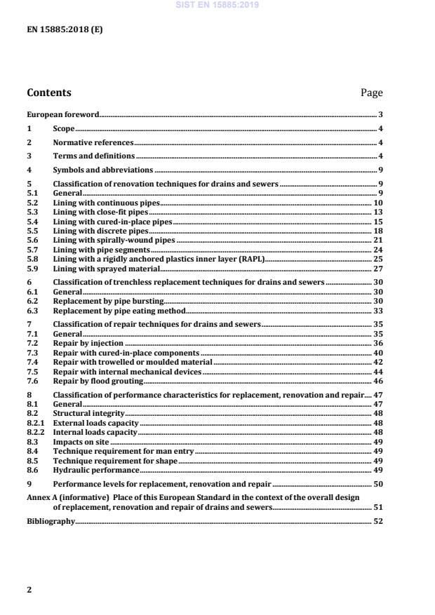
Place of this European Standard in the context of the overall design of replacement, renovation and repair of drains and sewers . 51 Bibliography . 52 SIST EN 15885:2019
11295:2017; c) Table 1 to Table 9 supplemented by features "Installation equipment", "Surface area" and "Excavation"; d) images partly adapted to EN ISO
11295:2017; e) sequence of sub-clauses 5.7 and 5.8 exchanged; f) technique family “Repair with trowelled material” (previous sub-clause 6.4) renamed “Repair with trowelled or moulded material”, and distinction between these techniques and Repair by injection clarified by extended text in new 7.2 and 7.4; g) editorial changes. This document refers to existing EN product standards to the extent available for the techniques and materials covered. It provides an overview of trenchless methods used for renovation and repair of drains and sewers, and for their replacement on the same line, regardless of the material used. In respect of sewer renovation
and replacement techniques using plastics materials only, it reproduces definitions and other information (but no requirements) contained in EN ISO 11295. Due to their continuous development the most up-to-date information on these particular techniques may be contained in either this document or EN ISO 11295, whichever is the latest edition. For management and control of rehabilitation activities in drains and sewers a European Standard EN 14654-2, Management and control of operational activities in drain and sewer systems outside buildings — Part 2: Rehabilitation is available. According to the CEN-CENELEC Internal Regulations, the national standards organisations of the following countries are bound to implement this European Standard: Austria, Belgium, Bulgaria, Croatia, Cyprus, Czech Republic, Denmark, Estonia, Finland, Former Yugoslav Republic of Macedonia, France, Germany, Greece, Hungary, Iceland, Ireland, Italy, Latvia, Lithuania, Luxembourg, Malta, Netherlands, Norway, Poland, Portugal, Romania, Serbia, Slovakia, Slovenia, Spain, Sweden, Switzerland, Turkey and the United Kingdom. SIST EN 15885:2019
a Other renovation techniques, which do not fit into the above families, are outside the scope of this European Standard which covers only technique families commonly available at the time of drafting. Figure 1 — Renovation technique families 5.2 Lining with continuous pipes Lining is carried out with a continuous pipe or a pipe made continuous, typically by butt-fusion, prior to insertion, where the cross section of the pipe used for lining remains unchanged. This technique is often referred to as slip-lining. Two methods of lining with continuous pipes are identified: — Method A: The lining pipe is smaller in diameter than the internal diameter of the host pipe to facilitate installation, and the host pipe itself is nominally round and without geometric defects. — Method B: The lining pipe is smaller in diameter than the internal diameter of the host pipe to facilitate installation, but the host pipe may have geometric defects that are corrected by using a ‘re-rounding pulling head’. A schematic representation of lining with continuous pipes, with re-rounding of existing pipeline, is shown in Figure 2. Features common to both methods are described in Table 1. SIST EN 15885:2019
Key 1 pulling and re-rounding head (only for Method B) 5 re-rounded defect 2 lining pipe 6 defects 3 prior jointing of lining pipe 7 existing pipe 4 pulling force
Figure 2 — Schematic representation of lining with continuous pipes with re-rounding of existing pipeline SIST EN 15885:2019
non-pressure pipes; —
pressure pipes. Geometric characteristics: —
minimum size:
100 mm; —
maximum size:
1 200 mm; —
maximum length:
750 m; —
capable of accommodating slightly curved alignments of the existing pipe. Performance: —
significant reduction in hydraulic (volumetric and flow) capacity; —
invert grade of liner can deviate from that of existing pipeline; —
structural rehabilitation is possible; —
abrasion resistance depends on liner material; —
chemical resistance depends on liner material. Installation characteristics: a)
pipes manufactured or prior assembled into the continuous length required; b)
insertion possible by pushing and/or pulling; c)
surface working space: storage of the whole insertion length required on surface: 1)
small diameters (typically
mm) can be supplied on coils, small space; 2)
larger diameters: supplied in straight lengths; d)
access to the existing pipeline: generally requires local excavation; e)
technique does not rely on adhesion to host pipe; f)
flow diversion is typically required for installation; g)
the annular space can be grouted, e.g. in non-pressure applications, to fix line and level and/or prevent subsequent movement; h)
live insertion is possible (but excl. drinking water applications for hygiene reasons); i)
reconnection of laterals: generally requires excavation. Installation equipment: —
rollers to support the entire length of the lining pipe string (except where pipe is inserted directly from a coil); —
pushing unit, if applicable; —
rollers to guide the lining pipe into the existing pipeline; —
winch or rod puller to pull the lining pipe through the existing pipeline; —
jointing equipment appropriate to the material; —
grouting equipment, if applicable. Surface area: —
for the lining pipe string (or coil trailer for smaller diameters) at the insertion end; —
for a winch or a rod puller at the receiving end. Excavation: —
at the insertion end: —
long enough to allow the lining pipe to enter the existing pipeline, taking account of the permissible minimum bending radius; —
wide enough for the guidance equipment and pushing equipment if applicable; —
at the receiving end: —
large enough to accommodate the lining pipe nose cone and the winch mast or rod puller, where applicable. SIST EN 15885:2019
Key 1 drum trailer 5 winch cable 2 pipe guide 6 winch 3 lining pipe (folded) 7 guide pulley 4 pulling head 8 bracing NOTE
Pipe reverted (unfolded) after insertion by application of heat and/or pressure. Figure 3 — Schematic representation of installation of a pipe reduced in cross section in the pipe manufacturing plant (Method A) SIST EN 15885:2019
Key 1 pulling head 4 winch or rod pulling device 2a initial lining pipe 5 guide pulley 2b reduced lining pipe 6 bracing cage 3 device for reducing
NOTE Pipe reverted (expanded or unfolded as applicable) after insertion by release of pulling force and application of pressure. Figure 4 — Schematic representation of installation of a pipe reduced in cross section on site (Method B) Table 2 — Features of lining with close fit pipes Feature Description Relevant documents: EN ISO 11296-3, EN ISO 11297-3 Materials: PE and PVC-U Applications: —
non-pressure pipes; —
pressure pipes. Geometric characteristics: —
some deviation from nominally circular shape possible; —
minimum size: 100 mm for both Method A and Method B; —
maximum size: 500 mm for Method A, 1 500 mm for Method B; —
maximum length: 500 m; —
some techniques can accommodate bends. Performance: —
minimal reduction in volumetric capacity; increase in flow due to reduced friction
possible; —
gradient cannot be restored; —
structural rehabilitation is possible; —
abrasion resistance depends on liner material; —
chemical resistance depends on liner material. SIST EN 15885:2019
lining pipe first reduced in size by mechanical or thermo-mechanical means (in the manufacturing plant or on site), inserted (in the case of PVC-U pre-heating generally required) and then reverted by relief of installation forces or application of heat and/or pressure; b)
surface working space: no particular constraint for Method A, storage of the whole insertion length can be required on surface for Method B (depends on specific technique); c)
access: typically through manhole for Method A, requires local excavation for Method B; d)
technique does not rely on adhesion to host pipe; e)
flow diversion is required; f)
grouting not applicable; g)
reconnection of laterals: 1)
gravity pipelines: possible from inside (re-opening and tight connection); 2)
in pressure applications: generally requires excavation. Installation equipment: —
rollers to support the entire length of the lining pipe string (except where pipe is inserted directly from a coil); —
guide for entrance of the lining pipe into the existing pipeline; —
winch to pull the lining pipe through the existing pipelinea; —
pushing unit, if applicable; —
a compressor and a steam generator (where applicable), or hydraulic pressurisation pump according to particular technique, for lining pipe reversion; —
jointing equipment appropriate to material. Surface area: —
for the lining pipe string (or coil trailer for smaller diameters and/or folded pipe) at the insertion end; —
for reducing or folding equipment at the insertion end where reduction or folding is carried out simultaneously with insertion; —
for a winch at the receiving end; —
for reversion equipment. Excavation: —
for Method A, not necessary for sewer applications, where access through existing manholes is sufficient due to flexibility of the lining pipe; in other applications, only small excavations at both ends; —
for Method B, at the insertion end: long enough to allow the lining pipe to enter the existing pipeline, taking account of the permissible minimum bending radius;
wide enough for the guidance equipment and pushing equipment, if applicable; —
at the receiving end: large enough to accommodate the lining pipe nose cone and longitudinal retraction during reversion of the lining pipe, if applicable. a
Where reducing is carried out simultaneously with insertion, winching forces can be high, necessitating substantial anchoring of winch and reducing equipment. 5.4 Lining with cured-in-place pipes Lining is carried out with a flexible tube impregnated with a thermosetting resin which produces a pipe after resin cure. Schematic representations are shown in Figures 5 and 6. Features are described in Table 3. SIST EN 15885:2019
Key 1 impregnated lining pipe 4 inversion face 2 applied water head for inversion 5 scaffold tower 3 water reservoir 6 clamping flange or ring Figure 5 — Schematic representation of lining with cured-in-place pipes installed by inversion (Method A)
Key 1 impregnated lining pipe 2 winch Figure 6 — Schematic representation of lining with cured-in-place pipes installed by winching and subsequent inflation (Method B) SIST EN 15885:2019
non-pressure pipes; —
pressure pipes. Geometric characteristics: —
circular and non-circular cross-section; —
minimum size:
100 mm; —
maximum size: 2 800 mm; —
maximum length: Method A: 600 m, Method B: 300 m; —
bends can be accommodated; —
change of dimensions can be accommodated. Performance: —
minimal reduction in volumetric capacity; increase in flow due to reduced friction possible; —
restoring of invert is not possible; —
structural rehabilitation is possible; —
abrasion resistance depends on wall structure; —
chemical resistance mainly depends on resin type. Installation characteristics: a)
insertion of the impregnated lining pipe, prior to curing, can be achieved by: 1)
inverting into position with
pressure only (water or air) or 2)
winching into place and then inflating; 3)
combinations of Methods A and B are also possible; b)
curing process can be initiated or accelerated by either: 1)
heat (hot water, steam); 2)
UV radiation; 3)
ambient temperature; c)
surface working space: generally minimal, varies with technique; d)
access: entry through existing manhole or small excavation possible; e)
structural effect does not rely on adhesion to host pipe; f)
flow diversion required; g)
re-opening of laterals from inside is possible; h)
reconnection of laterals: 1)
gravity pipelines: possible from inside (re-opening and tight connection); 2)
in pressure applications: generally requires excavation. Installation
equipment: —
lining pipe delivery unit, including conveyor system, if applicable; —
site impregnation unit, if applicable; —
for inverted-in-place systems: water column or air compressor; —
for winched-in-place systems: winch and water boiler or steam generator for heat curing, or equipment including power supply for UV. Surface area: —
for lining pipe delivery unit immediately adjacent to the insertion access; —
for site impregnation unit, if applicable; —
for inversion or winching equipment; —
for curing equipment. Excavation: —
not generally necessary for sewer applications, where access through existing manholes is sufficient due to flexibility of the uncured lining pipe; —
excavations at both ends for other applications. SIST EN 15885:2019
Key 1 thrust plate 3 jointed lining pipe 5 existing pipe 2 pushing device 4 pushing guide
NOTE The diameter of discrete pipes for insertion is slightly reduced against the existing pipe. Figure 7 — Schematic representation of installation by pushing (Method A)
Key 1 winch 4 stock of discrete pipes 2 pulling head 5 existing pipe 3 jointed lining pipe with end load bearing joints 6 re-rounding and pulling head Figure 8 — Schematic representation of installation by pulling (Method B) SIST EN 15885:2019
Key 1 manhole 2 individual discrete pipe being pulled or pushed into place 3 existing pipe 4 pipes already in position Figure 9 — Schematic representation of installation by individual pipe placement (Method C) SIST EN 15885:2019
pressure pipes; —
non-pressure pipes. Geometric characteristics: —
circular and non-circular cross-section; —
minimum size: Method A and B:
100 mm; Method C:
800 mm; —
maximum size: Method A and B:
600 mm; Method C:
4 000 mm; —
maximum length:
150 m; —
bends: bends with large radii can be accommodated by Method C only. Performance: —
significant reduction in hydraulic (volumetric and flow) capacity; —
uniform gradient can be restored using Method C in man-entry pipes; —
structural rehabilitation is possible; —
abrasion resistance depends on liner material; —
chemical resistance depends on liner material. Installation characteristics: —
the type of joint is a significant feature of each technique; —
pipe joints can be locked (end load bearing) or unlocked; —
surface working space: no particular constraint; —
access to the existing pipeline:
short pipe lengths can allow insertion from existing manholes (Methods A and B), but man-entry sizes installed by Method C can require local excavation; —
technique does not rely on adhesion on host pipe; —
flow diversion is typically required for installation and grouting; —
the annular space is typically grouted; —
reconnection of laterals: generally requires excavation; except in man-entry sizes. Installation
equipment: —
pipe handling equipment; —
generator to power pipe jacking equipment. Surface area: —
for storage of pipes, —
for pipe handling equipment, —
for a generator to power the pipe jacking equipment. Excavation: —
not generally necessary for sewer applications, access through manhole
due to availability of short pipe lengths; —
for other applications, excavation large enough to accommodate
jacking equipment at the insertion end; —
man-entry access needed at receiving end. SIST EN 15885:2019
Key 1 plastics strip to be spirally-wound 3 guidance head (where applicable) 2 winding machine in the manhole 4 spirally-wound lining pipe Figure 10 — Schematic representation of fixed diameter winding from the manhole (Method A1) SIST EN 15885:2019
Key 1 plastic strip to be spirally wound 2 winding machine in the manhole 3 spirally-wound lining pipe temporarily locked at reduced diameter for insertion 4 expanded diameter Figure 11 — Schematic representation of expanded liner winding from the manhole (Method A2)
Key 1 plastics strip to be spirally wound 2 winding machine in the pipe 3 spirally-wound liner Figure 12 — Schematic representation of winding of liner from pipe-traversing winding machine (Method B) SIST EN 15885:2019
non-pressure; —
applicable for manholes. Geometric characteristics: —
Method A circular cross-section only; Method B adaptable also to non-circular sections; —
minimum size: 150 mm for Method A; 800 mm for Method B; —
maximum size 3 000 mm for Method A, 1 800 mm for Method Ba; —
maximum length: 300 m; —
bends can be accommodated. Performance: —
reduction in capacity dependent on annular space and ratio of diameter
to overall profile height; —
uniform gradient can generally not be restored; —
structural renovation is possible; —
abrasion resistance depends on liner material; —
chemical resistance depends on liner material. Installation characteristics: —
lining pipe formed on site by spirally winding a strip, which is jointed
and sealed by solvent welding and/or mechanical means; —
individual winding machines can produce a range of diameters; —
no pipe storage on site; —
surface working space generally minimal; —
access through manholes possible; —
technique does not rely on adhesion to host pipe; —
flow diversion during installation is required for grouting and installation; —
grouting of annular space is required for fixed diameter; —
for (re)connection of laterals in non-man-entry pipes, local excavation
is generally required; reconnection from the inside is also possible. Installation equipment: —
strip winder; —
grouting equipment (if applicable). Surface area: —
for drums of liner strip at the insertion end; —
for a generator to power the winder at the insertion end. Excavation: —
manhole access sufficient due to flexibility of lining strip and small size
of the winder. a
Larger sizes are possible with steel reinforcement. SIST EN 15885:2019
Key 1 lining pipe segments 3 longitudinal joints 2 grout 4 existing pipe Figure 13 — Full and partial lining with pipe segments SIST EN 15885:2019
non-pressure pipes; Geometric characteristics: —
circular and non-circular cross-section; —
minimum size: man-entry sewer only; —
maximum size: no limit; —
maximum length: no limit; —
bends can be accommodated; —
change of dimensions can be accommodated. Performance: —
hydraulic performance: reduction in capacity dependent on annular space
and thickness in relation to diameter; uniform gradient can be restored; —
structural enhancement: structural renovation is possible; —
abrasion and chemical resistance: liner pipe material determines abrasion
and chemical resistance. Installation characteristics: —
jointing by either mechanical interlock or laminate/bonding; —
lining pipe segments prefabricated or shaped in place; —
mechanical link to host pipe using grouting, gluing and/or anchoring is
required; —
surface working space minimal at access point, but site storage for segments
required; —
access through manholes is possible; —
flow diversion dependent on safety requirements due to man entry; —
grouting of annular space is required; —
reconnection of laterals is possible from inside. Installation
equipment: —
winch; —
grouting equipment (if applicable). Surface areas: —
for material storage at the insertion end; —
for a generator to power the winch at the receiving end. Excavation: —
manhole access sufficient. 5.8 Lining with a rigidly anchored plastics inner layer (RAPL) Lining is carried out with a single rigid annulus of structural mineral material formed behind a plastics inner layer with integral profiles or studs permanently anchored to the grout. This technique family relies on the rigid annulus of grout for its structural performance. A schematic representation is shown in Figure 14. Features are described in Table 7. SIST EN 15885:2019
Key 1 anchored plastics inner layer 2 grout system 3 existing pipe 4 spacer (technique dependent) 5 anti-flotation spacers x height of anchors y minimum thickness of grout above height of anchors Figure 14 — Example of wall construction of a lining system with RAPL Several different types of plastics inner layer introduced by different techniques are in use. In addition to tubes of studded plastics sheeting winched in place and inflated prior to grouting, these include discrete pipes of plastics materials installed according to 5.5, profiled plastics strips formed into a pipe by spiral winding according to 5.6 or by other means, and pipe segments of plastics materials according to 5.7, where structural performance depends on permanent anchorage of the plastics component to a rigid annulus of cementitious grout. SIST EN 15885:2019
equipment: — winch, and — grouting equipment (if applicable); Surface area: — for material storage at the insertion end, and — for a generator to power the winch at the receiving end; Excavation: — manhole access sufficient. a Sizes up to 5 000 mm are possible with certain
...