

EN 15654-1:2018
(Main)Railway applications - Measurement of vertical forces on wheels and wheelsets - Part 1: On-track measurement sites for vehicles in service
- Abstract
The scope of this European Standard is restricted to the measurement of vertical wheel forces and calculation of derived quantities on vehicles in service. Measurements of a train in motion are used to estimate the static forces.
Derived quantities can be:
- axle loads;
- side to side load differences of a wheel set, bogie, vehicle;
- overall mass of vehicle or train set;
- mean axle load of a vehicle or train set.
This standard is not concerned with the evaluation of:
- dynamic wheel force or derived quantities;
- wheel condition (i.e. shape, profile, flats);
- lateral wheel force;
- combination of lateral and vertical wheel forces.
The standard defines accuracy classes for measurements to be made at any speed greater than 5 km/h within the calibrated range, which may be up to line speed.
The aim of this standard is to obtain measurement results that give representative values for the distribution of vertical wheel forces of a running vehicle, which under ideal conditions will be similar to those that can be obtained from a standing vehicle.
This standard does not impose any restrictions on the types of vehicles that can be monitored, or on which networks or lines the measuring system can be installed.
The standard lays down minimum technical requirements and the metrological characteristics of a system for measuring and evaluating a range of vehicle loading parameters. Also defined are accuracy classes for the parameters measured and the procedure for verifying the calibration.
The measuring system proposed in this standard should not be considered as safety critical. If the measuring system is connected to a train traffic command and control system then requirements that are not part of this standard may apply.
Measuring systems complying with this standard have the potential to enhance safety in the railway sector. However, the current operating and maintenance procedures rather than this standard are mandatory for ensuring safety levels in European rail networks.
- Status
- Withdrawn
- Publication Date
- 16-Jan-2018
- Withdrawal Date
- 06-Oct-2026
- Technical Committee
- CEN/TC 256 - Railway applications
- Drafting Committee
- CEN/TC 256/WG 10 - Vehicle/Track Interaction
- Current Stage
- 9960 - Withdrawal effective - Withdrawal
- Start Date
- 03-Sep-2023
- Completion Date
- 07-Oct-2026
- Directive
- 2008/57/EC - DIRECTIVE 2008/57/EC OF THE EUROPEAN PARLIAMENT AND OF THE COUNCIL of 17 June 2008 on the interoperability of the rail system within the Community (Recast)OJ Ref: C 282, C 282/3 OJ Date: 10-Aug-2018

Relations
- Effective Date
- 03-May-2023
- Effective Date
- 15-Jul-2026
- Effective Date
- 09-Feb-2026
- Effective Date
- 09-Feb-2026
- Effective Date
- 09-Feb-2026
- Effective Date
- 09-Feb-2026
- Effective Date
- 09-Feb-2026
- Effective Date
- 09-Feb-2026
- Effective Date
- 28-Jan-2026
- Effective Date
- 28-Jan-2026
- Effective Date
- 10-Mar-2021
Get Certified
Connect with accredited certification bodies for this standard

IRIS Certification (UNIFE)
International Railway Industry Standard certification.

TÜV SÜD Rail GmbH
TÜV SÜD railway certification services.

Bureau Veritas Railway Certification
Railway and transportation certification.
Sponsored listings
Frequently Asked Questions
EN 15654-1:2018 is a standard published by the European Committee for Standardization (CEN). Its full title is "Railway applications - Measurement of vertical forces on wheels and wheelsets - Part 1: On-track measurement sites for vehicles in service". This standard covers: The scope of this European Standard is restricted to the measurement of vertical wheel forces and calculation of derived quantities on vehicles in service. Measurements of a train in motion are used to estimate the static forces. Derived quantities can be: - axle loads; - side to side load differences of a wheel set, bogie, vehicle; - overall mass of vehicle or train set; - mean axle load of a vehicle or train set. This standard is not concerned with the evaluation of: - dynamic wheel force or derived quantities; - wheel condition (i.e. shape, profile, flats); - lateral wheel force; - combination of lateral and vertical wheel forces. The standard defines accuracy classes for measurements to be made at any speed greater than 5 km/h within the calibrated range, which may be up to line speed. The aim of this standard is to obtain measurement results that give representative values for the distribution of vertical wheel forces of a running vehicle, which under ideal conditions will be similar to those that can be obtained from a standing vehicle. This standard does not impose any restrictions on the types of vehicles that can be monitored, or on which networks or lines the measuring system can be installed. The standard lays down minimum technical requirements and the metrological characteristics of a system for measuring and evaluating a range of vehicle loading parameters. Also defined are accuracy classes for the parameters measured and the procedure for verifying the calibration. The measuring system proposed in this standard should not be considered as safety critical. If the measuring system is connected to a train traffic command and control system then requirements that are not part of this standard may apply. Measuring systems complying with this standard have the potential to enhance safety in the railway sector. However, the current operating and maintenance procedures rather than this standard are mandatory for ensuring safety levels in European rail networks.
The scope of this European Standard is restricted to the measurement of vertical wheel forces and calculation of derived quantities on vehicles in service. Measurements of a train in motion are used to estimate the static forces. Derived quantities can be: - axle loads; - side to side load differences of a wheel set, bogie, vehicle; - overall mass of vehicle or train set; - mean axle load of a vehicle or train set. This standard is not concerned with the evaluation of: - dynamic wheel force or derived quantities; - wheel condition (i.e. shape, profile, flats); - lateral wheel force; - combination of lateral and vertical wheel forces. The standard defines accuracy classes for measurements to be made at any speed greater than 5 km/h within the calibrated range, which may be up to line speed. The aim of this standard is to obtain measurement results that give representative values for the distribution of vertical wheel forces of a running vehicle, which under ideal conditions will be similar to those that can be obtained from a standing vehicle. This standard does not impose any restrictions on the types of vehicles that can be monitored, or on which networks or lines the measuring system can be installed. The standard lays down minimum technical requirements and the metrological characteristics of a system for measuring and evaluating a range of vehicle loading parameters. Also defined are accuracy classes for the parameters measured and the procedure for verifying the calibration. The measuring system proposed in this standard should not be considered as safety critical. If the measuring system is connected to a train traffic command and control system then requirements that are not part of this standard may apply. Measuring systems complying with this standard have the potential to enhance safety in the railway sector. However, the current operating and maintenance procedures rather than this standard are mandatory for ensuring safety levels in European rail networks.
EN 15654-1:2018 is classified under the following ICS (International Classification for Standards) categories: 45.060.01 - Railway rolling stock in general. The ICS classification helps identify the subject area and facilitates finding related standards.
EN 15654-1:2018 has the following relationships with other standards: It is inter standard links to EN 15654-1:2018+A1:2023, EN 15273-4:2025, EN 50122-1:2022, EN 50122-2:2022, EN 50121-5:2017, EN 50124-1:2017, EN 60529:1991, EN 50121-4:2016, EN 15273-3:2025, CEN/TR 15654-3:2019, EN 15654-1:2018/FprA1. Understanding these relationships helps ensure you are using the most current and applicable version of the standard.
EN 15654-1:2018 is associated with the following European legislation: EU Directives/Regulations: 2008/57/EC; Standardization Mandates: M/483. When a standard is cited in the Official Journal of the European Union, products manufactured in conformity with it benefit from a presumption of conformity with the essential requirements of the corresponding EU directive or regulation.
EN 15654-1:2018 is available in PDF format for immediate download after purchase. The document can be added to your cart and obtained through the secure checkout process. Digital delivery ensures instant access to the complete standard document.
Standards Content (Sample)
2003-01.Slovenski inštitut za standardizacijo. Razmnoževanje celote ali delov tega standarda ni dovoljeno.Železniške naprave - Meritve vertikalnih kolesnih in osnih obremenitev - 1. del: Meritve na železniških vozilih med vožnjoBahnanwendungen - Messung von vertikalen Rad- und Radsatzkräften - Teil 1: Interoperable gleisseitige Messeinrichtungen für fahrende FahrzeugeApplications ferroviaires - Mesurage des forces verticales à la roue et à l'essieu - Partie 1 : Sites de mesure en voie interopérables des véhicules en serviceRailway applications - Measurement of vertical forces on wheels and wheelsets - Part 1: On-track measurement sites for vehicles in service45.060.01Železniška vozila na splošnoRailway rolling stock in generalICS:Ta slovenski standard je istoveten z:EN 15654-1:2018SIST EN 15654-1:2018en,fr,de01-marec-2018SIST EN 15654-1:2018SLOVENSKI
STANDARD
EUROPEAN STANDARD NORME EUROPÉENNE EUROPÄISCHE NORM
EN 15654-1
January
t r s z ICS
v wä r x rä r s English Version
Railway applications æ Measurement of vertical forces on wheels and wheelsets æ Part
sã Onætrack measurement sites for vehicles in service Applications ferroviaires æ Mesurage des forces verticales à la roue et à l 5essieu æ Partie
s ã Sites de mesure en voie des véhicules en service
Bahnanwendungen æ Messung von vertikalen Radæ und Radsatzkräften æ Teil
sã Gleisseitige Messeinrichtungen für fahrende Fahrzeuge This European Standard was approved by CEN on
t { October
t r s yä
egulations which stipulate the conditions for giving this European Standard the status of a national standard without any alterationä Upætoædate lists and bibliographical references concerning such national standards may be obtained on application to the CENæCENELEC Management Centre or to any CEN memberä
translation under the responsibility of a CEN member into its own language and notified to the CENæCENELEC Management Centre has the same status as the official versionsä
CEN members are the national standards bodies of Austriaá Belgiumá Bulgariaá Croatiaá Cyprusá Czech Republicá Denmarká Estoniaá Finlandá Former Yugoslav Republic of Macedoniaá Franceá Germanyá Greeceá Hungaryá Icelandá Irelandá Italyá Latviaá Lithuaniaá Luxembourgá Maltaá Netherlandsá Norwayá Polandá Portugalá Romaniaá Serbiaá Slovakiaá Sloveniaá Spainá Swedená Switzerlandá Turkey and United Kingdomä
EUROPEAN COMMITTEE FOR STANDARDIZATION COMITÉ EUROPÉEN DE NORMALISATION EUROPÄISCHES KOMITEE FÜR NORMUNG
CEN-CENELEC Management Centre:
Rue de la Science 23,
B-1040 Brussels
t r s z CEN All rights of exploitation in any form and by any means reserved worldwide for CEN national Membersä Refä Noä EN
s w x w væ sã t r s z ESIST EN 15654-1:2018
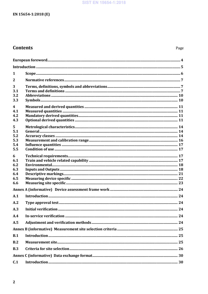
Device assessment frame work . 24 A.1 Introduction . 24 A.2 Type approval test . 24 A.3 Initial verification . 24 A.4 In-service verification . 24 A.5 Adjustment and verification methods . 24 Annex B (informative)
Measurement site selection criteria . 25 B.1 Introduction . 25 B.2 Measurement site . 25 B.3 Criteria for site selection . 26 Annex C (informative)
Data exchange format . 30 C.1 Introduction . 30 SIST EN 15654-1:2018
Usage of data and accuracy classes . 36 D.1 Introduction. 36 D.2 Typical applications . 36 Annex ZA (informative)
Relationship between this European Standard and the Essential Requirements of EU Directive 2008/57/EC aimed to be covered . 39 Bibliography . 41
The standard defines accuracy classes for measurements to be made at any speed greater than 5 km/h within the calibrated range, which may be up to line speed. The aim of this standard is to obtain measurement results that give representative values for the distribution of vertical wheel forces of a running vehicle, which under ideal conditions will be similar to those that can be obtained from a standing vehicle. This standard does not impose any restrictions on the types of vehicles that can be monitored, or on which networks or lines the measuring system can be installed. The standard lays down minimum technical requirements and the metrological characteristics of a system for measuring and evaluating a range of vehicle loading parameters. Also defined are accuracy classes for the parameters measured and the procedure for verifying the calibration. The measuring system proposed in this standard should not be considered as safety critical. If the measuring system is connected to a train traffic command and control system then requirements that are not part of this standard may apply. Measuring systems complying with this standard have the potential to enhance safety in the railway sector. However, the current operating and maintenance procedures rather than this standard are mandatory for ensuring safety levels in European rail networks. SIST EN 15654-1:2018
NOTE They are listed in the order in which they appear in the standard. 3.1.1 static vertical wheel force QF0,j,k representation of the vertical part of the static wheel force vector obtained from the dynamic measurement process of a vehicle in motion Note 1 to entry: Where the symbol QF0jk is used, j is the axle number and k is the vehicle side, k = R denotes the right hand side in the direction of travel and k = L denotes the left hand side in the direction of travel. 3.1.2 axle load sum of the static vertical wheel forces exerted on the track through a wheelset or a pair of independent wheels divided by acceleration of gravity 3.1.3 quantity property of a phenomenon, body, or substance, where the property has a magnitude that can be expressed as a number and a reference [SOURCE: ISO/IEC GUIDE 99] SIST EN 15654-1:2018
relative deviation
g acceleration due to gravity, minimum accuracy of 2 decimal places (m/s2) j wheelset index (1, 2, 3, …) i running gear index (1, 2, 3, …) k vehicle side
R for the right hand side in the direction of travel
L for the left hand side in the direction of travel
n total number of vehicles in the train
ntrn total number of wheelsets of the train
nveh total number of wheelsets of individual vehicle
nrg total number of running gear of individual vehicle
z number of wheelsets per running gear i
x number of first wheelset in running gear i
EN 15528 uses Q Individual wheelset force kN =+F0,F0,,LF0,,RjjjPQQ EN 14363:2005 uses 02jQ F0P Individual axle load t +=0,,L0,,R0,jjjQQPg EN 15528 uses P Train gross mass t =∑0,trnjjmP
where j
addresses each wheelset of the train
4.3 Optional derived quantities The following Table 2 defines optional derived quantities. Similar formulae should be used for other axle configurations, where applicable. SIST EN 15654-1:2018
where j
addresses each wheelset of the vehicle NOTE 1
j: wheelset indices of the vehicle
NOTE 2
Optional quantity, because there is no exact definition for a vehicle (e.g. articulated train/vehicle). EN 14363:2005 uses vehm Sum of wheel forces per running gear side kN =∑,0,,FrgkFjkjQQ
where j
addresses each wheelset of the running gear
Sum of axle loads per running gear t =∑0,rgjjPP
where j
addresses each wheelset of the running gear
Maximum axle load of the vehicle t =max,veh0,max()jPP where j
addresses each wheelset of the vehicle EN 14363:2005 uses0,max2Q
(in kN) Mean axle load of vehicle t Σ=0,jjvehvehPPn
where j
addresses each wheelset of the train or by =vehvehvehmPn
EN 14363:2005 uses 0,2meanQ (in kN) Mean axle load of running gear t Σ=0,jjrgPPz
where j
addresses each wheelset of the running gear
Diagonal imbalance ratio of adjacent running gears of the vehicle
- θ++++++=++rgLrg1RrgRrg1Ldiag,vehrgRrg1LrgLrg1RiiiiiiiiiQQQQQQQQ,,,,,,,,,,,,,,,,,max, HRMS uses dI SIST EN 15654-1:2018
- θ++++++=++0L01R0R01Ldiag,rg0R01L0L01RjjjjjjjjjQQQQQQQQ,,,,,,,,,,,,,,,,,max,
Diagonal imbalance ratio of the vehicle (side-to-side ratio)
- QθΣΣ=ΣΣ0,j,L0,j,Rlat,veh0,j,R0,j,LjjjjQQQmax,
where j
addresses each wheelset of the vehicle HRMS uses laI Diagonal imbalance ratio of the wheelset (side-to-side ratio)
- θ=0,j,L0,j,Rlat,0,j,R0,j,LjQQQQmax, HRMS uses aI Maximum longitudinal imbalance ratio of adjacent running gears in a vehicle (front-to rear ratio)
- θ−++==rg1rg, irg, i1long,vehrg, i1rg, i1 , niPPPPmaxmax NOTE
General formula (e.g. if you have two running gears it gives the front-rear ratio). HRMS uses loI Longitudinal imbalance ratio of adjacent running gears in a vehicle - θ−++==rg1rg, irg, i1long,rgrg, i1rg, i1 max, niPPPP
Relative side-to-side wheel force deviation of vehicle - ()()Σ−=Σ+0,,0,,side,veh0,,0,,jFjRFjLjFjRFjLQQqQQ
where j
addresses each wheelset of the vehicle EN 14363:2005 uses sideq Relative wheel force deviation per wheelset - −=+0,,R0,,L0,,R0,,LFjFjjFjFjQQqQQ
Relative deviation of difference between maximum axle load and mean axle load, and all derived by the mean axle load - −=veh0,vehvehmax()jPPpP EN 14363:2005 uses 0,maxq Relative deviation of mean axle loads between two running gears of a vehicle - ++−=+rg,rg,1rg,rg,rg,1iiiiiPPpPP
Relative axle load deviation inside running gear - −=rg,0,rg,rg,ijjiPPpP
5 Metrological characteristics 5.1 General In this clause of the standard, the minimum technical metrological characteristics, operational features and performance criteria are listed. 5.2 Accuracy classes The accuracy of a measurement system is defined in terms of ‘accuracy class’. The accuracy classes are based on the maximum permissible errors of the measurements and are specified in Table 3. In order to meet an accuracy class on initial verification, 90 % of the measurements shall not exceed the maximum permissible error specified for ‘initial verification’. The remaining 10 % shall not exceed the maximum permissible error specified for ‘in-service inspection’. In order to meet an accuracy class on in-service inspection, 100 % of the measurements shall not exceed the maximum permissible error specified for ‘in-service inspection’. A system may have different accuracy classes and shall be defined for one or more of the following quantities: a) train gross mass; b) vehicle gross mass; c) sum of axle loads on a running gear (bogie); d) axle load; e) wheel force. The accuracy classes may vary according to the direction of travel and whether the system is being operated in either the ‘pull mode’ or the ‘push mode’. To determine the accuracy classes of a measurement system, it is necessary to conduct verification tests with vehicles in motion. Verification of the accuracy classes of the quantities a) to e) shall be based on known values (measured by a system or several systems providing less uncertainty). Table 3 lists the available accuracy classes. These apply to the quantities a) to e) and can also be applied to quantities in Clause 4. The table specifies the accuracy per class for both initial and in-service verification. The range of full scale accuracy of measured values shall be defined. SIST EN 15654-1:2018
Key X vehicle mass
10 % in-service inspection (Class 10) 10 % of all measurements Y absolute error
5 % initial verification (Class 10) 90 % of all measurements Figure 1 — Illustration of accuracy classes and maximum permissible error for a class 10 device 5.3 Measurement and calibration range This measurement range is the range of wheel forces that the device shall measure. NOTE 1 This measurement range is related to the calculation of quasi-static quantities and may not be sufficient to measure peak dynamic forces generated by deficiencies (e.g. wheel defects, running instability, etc.). The measurement range is derived according to the following formulae which are based on the minimum defined axle load of the vehicles to be measured (P0,min) and the maximum permitted axle load of the track (P0,max.). See Figure 2. ⋅=⋅⋅∆0010352PgQq,min,minlim,
or by ⋅=∆⋅001702PgQq,max,maxlim,
where limq is the limit value for lateral imbalance per axlejq and is for this calculation 1,25. SIST EN 15654-1:2018
Key 0 zero point 1 Q0,min 2 nominal minimum wheel force derived from the minimum defined axle load P0,min 3
nominal maximum wheel force derived from the maximum permitted axle load on the line P0,max 4 Q0,max 5 measurement range and the minimum calibrated range for laboratory test 6 minimum calibrated range field test Figure 2 — Metrological characteristics NOTE 4 In cases where the scope of the intended measurements is restricted to detection of overloads, the minimum defined axle load and the maximum permitted axle load are the same. 5.4 Influence quantities An influence quantity is not the quantity being measured but affects the result of the measurement. Examples of influence quantities are track quality and geometry, speed of travel and speed change, running behaviour, vehicle condition and suspension, wheel quality, temperature, snow, wind and power supply. These influences should be taken into account in system and site selection. Recommendations for device assessment are shown in Annex A. 5.5 Condition of use The system shall only be used within its measurement range. The measuring system proposed in this standard is not considered to be essential for the safety of the railway system. If the measuring system is connected to a train traffic command and control system then requirements that are not part of this standard may apply. 6 Technical requirements 6.1 Train and vehicle related capability The system shall be designed to be capable of determining at least the mandatory quantities defined in Table 5 (Reported data) covering at least the ranges contained in Table 4. SIST EN 15654-1:2018
The measurement system shall be able to measure –static vertical wheel forces for train speeds greater than 5 km/h within the calibrated range. For vehicles having characteristics outside the ranges given in this table refer to the manufacturer’s specifications for the system performance. 6.2 Environmental Instruments shall comply with the appropriate metrological and technical requirements at ambient temperatures from 10 °C to +40 °C. For special applications, however, the limits of the temperature range may differ provided that this range is not less than 30 K and is specified in the descriptive markings. The equipment should comply with the minimum environmental requirements specified by the infrastructure operator according to EN 50125-2. Externally track mounted equipment shall have a minimum environmental rating of IP65 in accordance with EN 60529. When designing the measuring system, the following relevant parts of the prevailing standards related to the use of electrical and electronic equipment in railway applications shall be applied: EN 50121-4, EN 50121-5, EN 50122-1, EN 50122-2, EN 50124-1. In addition to complying with the applicable mandatory railway standards it is recommended that due consideration is given in the overall design of the measuring system to the environment in which it will be operated. Consideration should be given to the local conditions including weather conditions, vibration, electrical discharges, rodents and any special conditions prevailing at the site of the installation. 6.3 Inputs and Outputs For the specification of a measuring system according to the standard the following parameters shall be defined: — interface and communication means; — transmission protocol, message format; — Table 5 contains mandatory and optional requirements for the outputs of the measurement system. SIST EN 15654-1:2018
Location
Location identification code a M
id - (text or number) Locati
...