

EN IEC 60127-4:2026
(Main)Miniature fuses - Part 4: Universal modular fuse-links (UMF) - Through-hole and surface mount types
- Abstract
IEC 60127-4:2026 relates to universal modular fuse-links (UMF) for printed circuits and other substrate systems, used for the protection of electric appliances, electronic equipment, and component parts thereof, normally intended to be used indoors. It does not apply to fuse-links for appliances intended to be used under special conditions, such as in a corrosive or explosive atmosphere. These fuses are normally intended to be mounted or replaced only by appropriately skilled persons using specialized equipment. This document applies in addition to the requirements of IEC 60127-1. The objectives of this part of IEC 60127 are as given in IEC 60127-1, with the additional requirement of a degree of non-interchangeability. This fourth edition cancels and replaces the third edition published in 2005, Amendment 1:2008 and Amendment 2:2012. This edition constitutes a technical revision. This edition includes the following significant technical changes with respect to the previous edition: a) align to IEC 60127-1:2023, third edition; b) enhance the rated current of UMFs to 100A and provide the corresponding maximum voltage drop and maximum sustained dissipation; c) modify the figures; d) update the normative references to the latest version. This International Standard is to be used in conjunction with IEC 60127-1:2023
- Status
- Published
- Publication Date
- 17-Sep-2026
- Technical Committee
- CLC/SR 32C - Miniature fuses
- Current Stage
- 6060 - Document made available - Publishing
- Start Date
- 18-Sep-2026
- Due Date
- 23-Feb-2026
- Completion Date
- 18-Sep-2026


EN IEC 60127-4:2026 is the CLC standard for universal modular fuse-links (UMF) used on printed circuits and other substrate systems. It specifies through-hole and surface mount UMF for protecting electric appliances, electronic equipment, and their component parts, normally for indoor use. The standard is written for products mounted or replaced by appropriately skilled persons using specialized equipment, and it is used together with IEC 60127-1:2023.
What does EN IEC 60127-4:2026 specify?
EN IEC 60127-4:2026 sets additional requirements for UMF beyond the general miniature-fuse requirements in IEC 60127-1. It focuses on the product types, their ratings, marking, construction, test methods, and the standard sheets that define through-hole and surface mount versions.
The scope covers UMF for printed circuits and other substrate systems used in indoor equipment. It excludes fuse-links for special environments such as corrosive or explosive atmospheres. A key point in practice is that the series is not just about electrical protection - it also includes a degree of non-interchangeability so that the fuse-link type cannot be freely swapped without checking the intended application.
The document is organized into:
- Clause 1 Scope and object
- Clause 2 Normative references
- Clause 3 Terms and definitions
- Clause 4 General requirements
- Clause 5 Standard ratings
- Clause 6 Marking
- Clause 7 General notes on tests
- Clause 8 Dimensions and construction
- Clause 9 Electrical requirements
- Clause 10 Standard sheets
- Annex A, informative, on mounting for surface mount fuse-links
What are the key requirements of EN IEC 60127-4:2026?
EN IEC 60127-4:2026 ties UMF design and testing to the general rules in IEC 60127-1, then adds requirements specific to through-hole and surface mount fuse-links. In practice, the standard tells manufacturers how to define ratings, build the fuse-link, mount it for tests, and prove that it behaves correctly in operation.
Ratings and product identification
Clause 5 and the standard sheets define the rated voltage, rated current, and rated breaking capacity. Table 1 gives preferred rated currents and the corresponding maximum voltage drop and maximum sustained dissipation, and the table note allows intermediate rated currents from the R20 or R40 series in ISO 3. The table note also states that through-hole fuse-links are not meant for rated currents above 20 A.
Clause 6 adds marking rules specific to UMF. For 250 V fuse-links, the breaking-capacity symbol H, I, or L is marked between rated current and rated voltage. The distinctive UMF symbol is required, and devices designed only for alternating current are marked with a.c. This matters because the marking must clearly show how the fuse-link may be used and what breaking capacity it has.
Dimensions, construction, and terminations
Clause 8 requires the UMF dimensions to match the relevant standard sheet and checks them by measuring length, width, and height. The fuse-element must be completely enclosed, and the fuse-link must withstand the heat and chemical exposure of PCB or substrate assembly without performance loss.
Termination design is different for the two product families:
- Through-hole fuse-links are mounted on a printed wiring board with leads in holes.
- Surface mount fuse-links are attached directly to the substrate surface.
Clause 8 also gives the tests for attachment strength, alignment, solderability, and resistance to soldering heat. In practice, this means the termination style and spacing are not only a mechanical detail - they are part of the compliance check.
Test boards and mounting for verification
Clause 7 requires fuse-links to be soldered to the appropriate test board. The boards are based on epoxide woven glass fabric copper-clad laminate, and the manufacturer has to declare the PCB parameters listed in Table 6 and provide assembled PCBs for the tests.
Through-hole and surface mount fuse-links use different test boards and mounting arrangements in Figures 2 and 3. Clause 7 also specifies the test fuse-base in Figure 4 and the conductor sizes for higher currents in Table 17. For laboratories, this makes the test setup part of the standard, not a free choice.
Solderability and resistance to soldering heat
Clause 8.6 gives separate solderability methods for through-hole and surface mount fuse-links. Clause 8.7 gives separate resistance-to-soldering-heat methods for the two types as well. After testing, the terminations must remain sound, the fuse-link must not be cracked, marking must remain readable, and any colour coding must not change.
This matters because UMF are assembled with soldering processes, and the standard checks that normal PCB assembly temperatures do not damage the fuse-link or its identification.
Electrical performance
Clause 9 covers voltage drop, time/current characteristics, breaking capacity, endurance, sustained dissipation, pulse tests, fuse-link temperature, and operating overvoltage. The time/current performance is defined at normal ambient temperature with characteristic types FF, F, T, and TT.
Breaking capacity testing uses different a.c. power factors and d.c. time constants depending on whether the fuse-link is low-, intermediate-, or high-breaking capacity. Clause 9 also requires insulation resistance after breaking-capacity testing and sets a limit on operating overvoltage that is checked during the fault test. In practice, this is the core safety proof for selection and certification.
Standard sheets
Clause 10 gives two standard sheets:
- Standard sheet 1 - through-hole fuse-links
- Standard sheet 2 - surface mount fuse-links
The sheets define the permitted dimensions, termination spacing, markings, test currents, and overvoltage values for each family. They are the main selection pages for designers and buyers because they link the generic requirements to actual product forms.
What terms does EN IEC 60127-4:2026 define?
- Universal modular fuse-link (UMF) - a miniature fuse-link used on printed circuits and other substrate systems, with standardized forms for through-hole or surface mount use.
- Through-hole fuse-link - a UMF designed for soldering into a printed wiring board with its leads inserted into holes.
- Surface mount fuse-link - a UMF designed for direct attachment to the substrate surface without lead insertion into holes or sockets.
- Land - the conductive pattern area used for attachment of a component, especially relevant for surface mount design.
- Rated breaking capacity - the fault-current performance level that the fuse-link is intended to interrupt safely.
- Pre-arcing time - the time before the fuse-link element opens under overcurrent, used to classify FF, F, T, and TT behavior.
- a.c. - alternating current, used for fuse-links designed only for alternating-current applications.
- d.c. - direct current, used where the fuse-link is rated and tested for direct-current use.
Who uses EN IEC 60127-4:2026?
EN IEC 60127-4:2026 is used by fuse manufacturers, PCB and product designers, test laboratories, quality teams, and buyers specifying miniature protection devices. It is relevant in the electronics, appliance, and component industries wherever protected circuits use UMF on printed circuits or other substrate systems.
Designers use it to choose the right mounting style, footprint, rated current, and rated voltage. Test and certification teams use it to set up solderability, endurance, breaking-capacity, temperature-rise, and overvoltage tests. Buyers and quality managers use it to compare fuse-link families and check that the selected part matches the intended application and mounting method.
What changed in EN IEC 60127-4:2026 from the previous edition?
EN IEC 60127-4:2026 cancels and replaces the third edition published in 2005, Amendment 1:2008 and Amendment 2:2012. The edition is described as a technical revision.
The stated changes are:
- alignment to IEC 60127-1:2023
- increased rated current for UMF to 100 A, with the corresponding maximum voltage drop and maximum sustained dissipation
- modified figures
- updated normative references to the latest versions
Which standards are used with EN IEC 60127-4:2026?
EN IEC 60127-4:2026 is used in conjunction with IEC 60127-1:2023, which supplies the general definitions and requirements for miniature fuse-links. The other normative references support the test methods, PCB terminology, insulation coordination, and preferred ratings used in this part.
- IEC 60068-2-21:2021 - test methods for robustness of terminations and integral mounting devices
- IEC 60068-2-58:2015+AMD1:2017 - solderability and resistance to soldering heat for surface mounting devices
- IEC 60127-1:2023 - general miniature-fuse definitions and requirements
- IEC 60194:2021 - terms and definitions for printed board design, manufacture, and assembly
- IEC 60216-1:2013 - thermal endurance properties for insulating materials
- IEC 60664-1:2020 - insulation coordination and overvoltage-related principles
- IEC 61249-2-7:2002 - base materials for printed boards
- IPC 7351B:2010 - land pattern standard for surface mount design
- ISO 3:1973 - preferred numbers series used for intermediate ratings
What does the EN IEC 60127-4:2026 document contain?
EN IEC 60127-4:2026 contains the UMF unique identifying symbol, the through-hole and surface mount test-board figures, the test fuse base, the bending jig, and the breaking-capacity test circuits. It also includes tables for preferred ratings, conductor cross-sections, test schedules, copper track specifications, and the maximum voltage drop and sustained dissipation limits.
The standard sheets give the practical product data used in design and procurement: permitted dimensions, terminal spacing, marking, time/current behavior, breaking-capacity test conditions, and endurance-test conditions. Annex A adds mounting guidance for surface mount fuse-links, including reflow-related parameters and solder-paste preparation points.
Relations
- Effective Date
- 05-Dec-2023
- Effective Date
- 05-Dec-2023
- Effective Date
- 05-Dec-2023
- Effective Date
- 01-Sep-2026
- Effective Date
- 01-Sep-2026
- Effective Date
- 01-Sep-2026
- Effective Date
- 01-Sep-2026
- Effective Date
- 01-Sep-2026
- Effective Date
- 01-Sep-2026
- Effective Date
- 01-Sep-2026
- Effective Date
- 01-Sep-2026
- Effective Date
- 01-Sep-2026
- Effective Date
- 01-Sep-2026
- Effective Date
- 01-Sep-2026
- Effective Date
- 22-Sep-2026
Get Certified
Connect with accredited certification bodies for this standard

IMQ S.p.A. (Certification)
Italian electrical product certification.

SLG Prüf- und Zertifizierungs GmbH
German testing and certification body.

UL Solutions
Global safety science company with testing, inspection and certification.
Sponsored listings
Frequently Asked Questions
EN IEC 60127-4:2026 is a draft published by CLC. Its full title is "Miniature fuses - Part 4: Universal modular fuse-links (UMF) - Through-hole and surface mount types". This standard covers: IEC 60127-4:2026 relates to universal modular fuse-links (UMF) for printed circuits and other substrate systems, used for the protection of electric appliances, electronic equipment, and component parts thereof, normally intended to be used indoors. It does not apply to fuse-links for appliances intended to be used under special conditions, such as in a corrosive or explosive atmosphere. These fuses are normally intended to be mounted or replaced only by appropriately skilled persons using specialized equipment. This document applies in addition to the requirements of IEC 60127-1. The objectives of this part of IEC 60127 are as given in IEC 60127-1, with the additional requirement of a degree of non-interchangeability. This fourth edition cancels and replaces the third edition published in 2005, Amendment 1:2008 and Amendment 2:2012. This edition constitutes a technical revision. This edition includes the following significant technical changes with respect to the previous edition: a) align to IEC 60127-1:2023, third edition; b) enhance the rated current of UMFs to 100A and provide the corresponding maximum voltage drop and maximum sustained dissipation; c) modify the figures; d) update the normative references to the latest version. This International Standard is to be used in conjunction with IEC 60127-1:2023
IEC 60127-4:2026 relates to universal modular fuse-links (UMF) for printed circuits and other substrate systems, used for the protection of electric appliances, electronic equipment, and component parts thereof, normally intended to be used indoors. It does not apply to fuse-links for appliances intended to be used under special conditions, such as in a corrosive or explosive atmosphere. These fuses are normally intended to be mounted or replaced only by appropriately skilled persons using specialized equipment. This document applies in addition to the requirements of IEC 60127-1. The objectives of this part of IEC 60127 are as given in IEC 60127-1, with the additional requirement of a degree of non-interchangeability. This fourth edition cancels and replaces the third edition published in 2005, Amendment 1:2008 and Amendment 2:2012. This edition constitutes a technical revision. This edition includes the following significant technical changes with respect to the previous edition: a) align to IEC 60127-1:2023, third edition; b) enhance the rated current of UMFs to 100A and provide the corresponding maximum voltage drop and maximum sustained dissipation; c) modify the figures; d) update the normative references to the latest version. This International Standard is to be used in conjunction with IEC 60127-1:2023
EN IEC 60127-4:2026 is classified under the following ICS (International Classification for Standards) categories: 29.120.50 - Fuses and other overcurrent protection devices. The ICS classification helps identify the subject area and facilitates finding related standards.
EN IEC 60127-4:2026 has the following relationships with other standards: It is inter standard links to EN 60127-4:2005, EN 60127-4:2005/A2:2013, EN 60127-4:2005/A1:2009, EN IEC 60068-2-21:2021, ISO 3:1973, EN 61249-2-7:2002, EN 60068-2-58:2015, EN IEC 60664-1:2020, EN IEC 60068-2-20:2021, EN 60216-1:2013, EN 60068-2-58:2015/A1:2018, EN IEC 60664-1:2020/A1:2025, IEC 60194-1:2021, EN IEC 60127-1:2024, EN IEC 60335-1:2023. Understanding these relationships helps ensure you are using the most current and applicable version of the standard.
EN IEC 60127-4:2026 is associated with the following European legislation: EU Directives/Regulations: 2014/35/EU; Standardization Mandates: M/511. When a standard is cited in the Official Journal of the European Union, products manufactured in conformity with it benefit from a presumption of conformity with the essential requirements of the corresponding EU directive or regulation.
EN IEC 60127-4:2026 is available in PDF format for immediate download after purchase. The document can be added to your cart and obtained through the secure checkout process. Digital delivery ensures instant access to the complete standard document.
Standards Content (Sample)
SLOVENSKI STANDARD
oSIST prEN IEC 60127-4:2024
01-december-2024
Miniaturne varovalke – 4. del: Univerzalni modularni taljivi vložki – Skoznji vložki in
vložki za površinsko montažo
Miniature fuses - Part 4: Universal modular fuse-links (UMF) - Through-hole and surface
mount types
Geräteschutzsicherungen - Teil 4: Welteinheitliche modulare Sicherungseinsätze (UMF)
- Bauarten für Steck- und Oberflächenmontage
Coupe-circuit miniatures - Partie 4: Eléments de remplacement modulaires universels
(UMF) - Types de montage en surface et montage par trous
Ta slovenski standard je istoveten z: prEN IEC 60127-4:2024
ICS:
29.120.50 Varovalke in druga Fuses and other overcurrent
nadtokovna zaščita protection devices
oSIST prEN IEC 60127-4:2024 en,fr,de
2003-01.Slovenski inštitut za standardizacijo. Razmnoževanje celote ali delov tega standarda ni dovoljeno.
oSIST prEN IEC 60127-4:2024
oSIST prEN IEC 60127-4:2024
32C/646/CDV
COMMITTEE DRAFT FOR VOTE (CDV)
PROJECT NUMBER:
IEC 60127-4 ED4
DATE OF CIRCULATION: CLOSING DATE FOR VOTING:
2024-10-18 2025-01-10
SUPERSEDES DOCUMENTS:
32C/629/CD, 32C/640A/CC
IEC SC 32C : MINIATURE FUSES
SECRETARIAT: SECRETARY:
China Mr Jun Cai
OF INTEREST TO THE FOLLOWING COMMITTEES: HORIZONTAL FUNCTION(S):
ASPECTS CONCERNED:
Safety
SUBMITTED FOR CENELEC PARALLEL VOTING NOT SUBMITTED FOR CENELEC PARALLEL VOTING
Attention IEC-CENELEC parallel voting
The attention of IEC National Committees, members of
CENELEC, is drawn to the fact that this Committee Draft
for Vote (CDV) is submitted for parallel voting.
The CENELEC members are invited to vote through the
CENELEC online voting system.
This document is still under study and subject to change. It should not be used for reference purposes.
Recipients of this document are invited to submit, with their comments, notification of any relevant patent rights of
which they are aware and to provide supporting documentation.
Recipients of this document are invited to submit, with their comments, notification of any relevant “In Some
Countries” clauses to be included should this proposal proceed. Recipients are reminded that the CDV stage is
the final stage for submitting ISC clauses. (SEE AC/22/2007 OR NEW GUIDANCE DOC).
TITLE:
Miniature fuses - Part 4: Universal modular fuse-links (UMF) - Through-hole and surface mount
types
PROPOSED STABILITY DATE: 2027
NOTE FROM TC/SC OFFICERS:
electronic file, to make a copy and to print out the content for the sole purpose of preparing National Committee positions.
You may not copy or "mirror" the file or printed version of the document, or any part of it, for any other purpose without
permission in writing from IEC.
oSIST prEN IEC 60127-4:2024
IEC CDV 60127-4/Ed4 © IEC 2024 – 2 – 32C/646/CDV
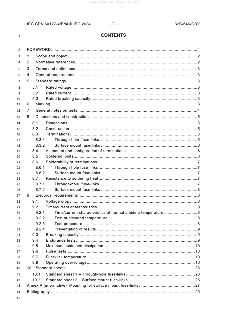
1 CONTENTS
2 FOREWORD . 4
3 1 Scope and object . 2
4 2 Normative references . 2
5 3 Terms and definitions . 3
6 4 General requirements . 3
7 5 Standard ratings . 3
8 5.1 Rated voltage . 3
9 5.2 Rated current . 3
10 5.3 Rated breaking capacity. 3
11 6 Marking . 3
12 7 General notes on tests . 4
13 8 Dimensions and construction . 5
14 8.1 Dimensions . 5
15 8.2 Construction . 5
16 8.3 Terminations . 6
17 8.3.1 Through-hole fuse-links . 6
18 8.3.2 Surface mount fuse-links . 6
19 8.4 Alignment and configuration of terminations . 6
20 8.5 Soldered joints . 6
21 8.6 Solderability of terminations . 7
22 8.6.1 Through-hole fuse-links . 7
23 8.6.2 Surface mount fuse-links . 7
24 8.7 Resistance to soldering heat . 7
25 8.7.1 Through-hole fuse-links . 7
26 8.7.2 Surface mount fuse-links . 8
27 9 Electrical requirements . 8
28 9.1 Voltage drop . 8
29 9.2 Time/current characteristics . 8
30 9.2.1 Time/current characteristics at normal ambient temperature . 8
31 9.2.2 Test at elevated temperature . 8
32 9.2.3 Test procedure . 8
33 9.2.4 Presentation of results . 9
34 9.3 Breaking capacity . 9
35 9.4 Endurance tests . 9
36 9.5 Maximum sustained dissipation . 10
37 9.6 Pulse tests . 10
38 9.7 Fuse-link temperature . 10
39 9.8 Operating overvoltage . 10
40 10 Standard sheets . 23
41 10.1 Standard sheet 1 – Through-hole fuse-links . 23
42 10.2 Standard sheet 2 – Surface mount fuse-links . 25
43 Annex A (informative) Mounting for surface mount fuse-links . 27
44 Bibliography . 29
oSIST prEN IEC 60127-4:2024
IEC CDV 60127-4/Ed4 © IEC 2024 – 3 – 32C/XXX/CDV
46 Figure 1 – Unique identifying symbol for UMFs . 15
47 Figure 2 – Test board for through-hole fuse-links . 16
48 Figure 3 – Test board for surface mount fuse-links . 18
49 Figure 4 – Test fuse base . 19
50 Figure 5 – Bending jig for surface mount fuse-links . 20
51 Figure 6 – Test circuits for breaking capacity tests . 21
52 Figure A.1 – Parameters for reflow temperature . 28
54 Table 17 – Cross-sections of conductors . 5
55 Table 1 – Maximum values of voltage drop and sustained dissipation . 11
56 Table 2 – Testing schedule for individual ampere ratings . 12
57 Table 3 – Testing schedule for maximum ampere rating of a homogeneous series . 13
58 Table 4 – Testing schedule for minimum ampere rating of a homogeneous series . 15
59 Table 5 – Copper track specifications for test board for surface mount fuse-links . 22
oSIST prEN IEC 60127-4:2024
IEC CDV 60127-4/Ed4 © IEC 2024 – 4 – 32C/646/CDV
62 INTERNATIONAL ELECTROTECHNICAL COMMISSION
63 ____________
65 MINIATURE FUSES –
67 Part 4: Universal modular fuse-links (UMF) –
68 Through-hole and surface mount types
70 FOREWORD
71 1) The International Electrotechnical Commission (IEC) is a worldwide organization for standardization comprising
72 all national electrotechnical committees (IEC National Committees). The object of IEC is to promote international
73 co-operation on all questions concerning standardization in the electrical and electronic fields. To this end and
74 in addition to other activities, IEC publishes International Standards, Technical Specifications, Technical Reports,
75 Publicly Available Specifications (PAS) and Guides (hereafter referred to as “IEC Publication(s)”). Their
76 preparation is entrusted to technical committees; any IEC National Committee interested in the subject dealt with
77 may participate in this preparatory work. International, governmental and non-governmental organizations liaising
78 with the IEC also participate in this preparation. IEC collaborates closely with the International Organization for
79 Standardization (ISO) in accordance with conditions determined by agreement between the two organizations.
80 2) The formal decisions or agreements of IEC on technical matters express, as nearly as possible, an international
81 consensus of opinion on the relevant subjects since each technical committee has representation from all
82 interested IEC National Committees.
83 3) IEC Publications have the form of recommendations for international use and are accepted by IEC National
84 Committees in that sense. While all reasonable efforts are made to ensure that the technical content of IEC
85 Publications is accurate, IEC cannot be held responsible for the way in which they are used or for any
86 misinterpretation by any end user.
87 4) In order to promote international uniformity, IEC National Committees undertake to apply IEC Publications
88 transparently to the maximum extent possible in their national and regional publications. Any divergence between
89 any IEC Publication and the corresponding national or regional publication shall be clearly indicated in the latter.
90 5) IEC itself does not provide any attestation of conformity. Independent certification bodies provide conformity
91 assessment services and, in some areas, access to IEC marks of conformity. IEC is not responsible for any
92 services carried out by independent certification bodies.
93 6) All users should ensure that they have the latest edition of this publication.
94 7) No liability shall attach to IEC or its directors, employees, servants or agents including individual experts and
95 members of its technical committees and IEC National Committees for any personal injury, property damage or
96 other damage of any nature whatsoever, whether direct or indirect, or for costs (including legal fees) and
97 expenses arising out of the publication, use of, or reliance upon, this IEC Publication or any other IEC
98 Publications.
99 8) Attention is drawn to the Normative references cited in this publication. Use of the referenced publications is
100 indispensable for the correct application of this publication.
101 9) IEC draws attention to the possibility that the implementation of this document may involve the use of (a)
102 patent(s). IEC takes no position concerning the evidence, validity or applicability of any claimed patent rights in
103 respect thereof. As of the date of publication of this document, IEC [had/had not] received notice of (a) patent(s),
104 which may be required to implement this document. However, implementers are cautioned that this may not
105 represent the latest information, which may be obtained from the patent database available at
106 https://patents.iec.ch. IEC shall not be held responsible for identifying any or all such patent rights.
107 IEC 6XXXX has been prepared by subcommittee XX: TITLE, of IEC technical committee XX:
108 TITLE. It is an International Standard.
109 This XXX edition cancels and replaces the XXX edition published in [publication_date],
110 Amendment 1:[publication_date] and Amendment 2:[publication_date]. This edition constitutes
111 a technical revision.
112 This edition includes the following significant technical changes with respect to the previous
113 edition:
114 a) .;
115 b)
oSIST prEN IEC 60127-4:2024
IEC CDV 60127-4/Ed4 © IEC 2024 – 5 – 32C/XXX/CDV
116 The text of this International Standard is based on the following documents:
Draft Report on voting
32C/XX/FDIS 32C/XX/RVD
118 Full information on the voting for its approval can be found in the report on voting indicated in
119 the above table.
120 The language used for the development of this International Standard is English [change
121 language if necessary].
122 This document was drafted in accordance with ISO/IEC Directives, Part 2, and developed in
123 accordance with ISO/IEC Directives, Part 1 and ISO/IEC Directives, IEC Supplement, available
124 at www.iec.ch/members_experts/refdocs. The main document types developed by IEC are
125 described in greater detail at www.iec.ch/publications.
126 The committee has decided that the contents of this document will remain unchanged until the
127 stability date indicated on the IEC website under webstore.iec.ch in the data related to the
128 specific document. At this date, the document will be
129 • reconfirmed,
130 • withdrawn, or
131 • revised.
oSIST prEN IEC 60127-4:2024
IEC CDV 60127-4/Ed4 © IEC 2024 – 2 – 32C/646/CDV
134 MINIATURE FUSES –
136 Part 4: Universal modular fuse-links (UMF) –
137 Through-hole and surface mount types
141 1 Scope and object
142 This part of IEC 60127 relates to universal modular fuse-links (UMF) for printed circuits and
143 other substrate systems, used for the protection of electric appliances, electronic equipment,
144 and component parts thereof, normally intended to be used indoors.
145 It does not apply to fuse-links for appliances intended to be used under special conditions, such
146 as in a corrosive or explosive atmosphere.
147 These fuses are normally intended to be mounted or replaced only by appropriately skilled
148 persons using specialized equipment.
149 This standard applies in addition to the requirements of IEC 60127-1.
150 The objectives of this part of IEC 60127 are as given in IEC 60127-1, with the additional
151 requirement of a degree of non-interchangeability.
152 2 Normative references
153 The following documents are referred to in the text in such a way that some or all of their content
154 constitutes requirements of this document. For dated references, only the edition cited applies.
155 For undated references, the latest edition of the referenced document (including any
156 amendments) applies.
157 IEC 60068-2-21:2021, Environmental testing – Part 2-21: Tests – Test U: Robustness of
158 terminations and integral mounting devices
159 IEC 60068-2-58:2015+AMD1:2017, Environmental testing – Part 2-58: Tests – Test Td: Test
160 methods for solderability, resistance to dissolution of metallization and to soldering heat of
161 surface mounting devices (SMD)
162 IEC 60127-1:2023, Miniature fuses – Part 1: Definitions for miniature fuses and general
163 requirements for miniature fuse-links
164 IEC 60194:2021, Printed board design, manufacture and assembly – Terms and definitions
165 IEC 60216-1: 2013, Electrical insulating materials – Thermal endurance properties – Part 1:
166 Ageing procedures and evaluation of test results
167 IEC 60664-1:2020, Insulation coordination for equipment within low-voltage systems – Part 1:
168 Principles, requirements and tests
169 IEC 61249-2-7:2002, Materials for printed boards and other interconnecting structures –
170 Part 2-7: Reinforced base materials clad and unclad – Epoxide woven E-glass laminated sheet
171 of defined flammability (vertical burning test), copper-clad
172 IPC 7351B:2010, Generic requirements for surface mount design and land pattern standard
oSIST prEN IEC 60127-4:2024
IEC CDV 60127-4/Ed4 © IEC 2024 – 3 – 32C/XXX/CDV
173 ISO 3:1973, Preferred numbers – Series of preferred numbers
174 3 Terms and definitions
175 For the purposes of this document, the terms and definitions given in Clause 3 of IEC 60127-1,
176 together with the following definitions, apply.
177 3.1
178 through-hole fuse-link
179 UMF designed for soldering directly into a printed wiring board, with insertion of its leads in
180 suitably designed holes
181 3.2
182 surface mount fuse-link
183 UMF designed for direct conductive attachment by solder or other means on to the surface of
184 a substrate, without insertion of its leads in suitably designed holes or sockets
185 3.3
186 land
187 portion of a conductive pattern usually but not exclusively used for the connection and/or
188 attachment of components (see IEC 60194)
189 Note 1 to entry: Further definitions which may be useful in the application of surface mount fuse-links may be found
190 in IEC 60115-1 and IEC 60115-8 .
191 4 General requirements
192 See IEC 60127-1.
193 5 Standard ratings
194 5.1 Rated voltage
195 See standard sheets.
196 5.2 Rated current
197 See Table 1 for preferred ratings.
198 5.3 Rated breaking capacity
199 See standard sheets.
200 6 Marking
201 In addition to the requirements of Clause 6 in IEC 60127-1, the following criteria concerning
202 UMF shall be observed and marked:
___________
This standard has been withdrawn.
oSIST prEN IEC 60127-4:2024
IEC CDV 60127-4/Ed4 © IEC 2024 – 4 – 32C/646/CDV
203 6.1 Addition:
204 e) For fuse-links rated at 250 V, a symbol denoting the breaking capacity. This symbol shall
205 be placed between the marking for rated current and the marking for rated voltage.
206 These symbols are as follows:
207 H: denoting high-breaking capacity;
208 I: denoting intermediate-breaking capacity;
209 L: denoting low-breaking capacity.
210 f) The distinctive symbol shown in Figure 1.
211 g) The letters a.c. before the voltage for devices designed solely for alternating current
212 application.
213 6.4 Colour coding for universal modular fuse-links
214 Under consideration.
215 6.5 Where marking is impractical due to space limitations, the relevant information should
216 appear on the smallest package and in the manufacturer’s technical literature.
217 7 General notes on tests
218 In addition to the requirements of Clause 7 in IEC 60127-1, the following criteria shall be
219 observed:
220 7.2 Addition:
221 7.2.1 For testing of individual fuse ratings according to standard sheets 1 and 2, see Table 2.
222 For fuse-links designed and rated both for a.c. and d.c., the number of fuse-links required is 63.
223 For fuse-links designed only for a.c., the number of fuse-links required is 48. There are nine
224 spares.
225 For the maximum ampere rating of a homogeneous series according to standard sheets 1 and
226 2, see Table 3. For fuse-links designed and rated both for a.c. and d.c., the number of fuse-
227 links required is 53. For fuse-links designed only for a.c., the number of fuse-links required is
228 48. There are 19 spares.
229 For the minimum ampere rating of a homogeneous series according to standard sheets 1 and
230 2, see Table 4. For fuse-links designed and rated both for a.c. and d.c., the number of fuse links
231 required is 38. For fuse-links designed only for a.c., the number of fuse-links required is 33.
232 There are 16 spares.
233 7.3 Fuse-bases for tests
234 7.3.1 General requirements
235 Fuse-links shall be mounted upon the appropriate test board (see 7.3.2 or 7.3.3 as appropriate)
236 by soldering.
237 The test board shall be made of epoxide woven glass fabric copper-clad laminated sheet, as
238 defined in IEC 61249-2-7:
239 − the nominal sheet thickness shall be 1,6 mm;
240 − the nominal thickness of copper layer shall be in accordance with Table 6.
241 The manufacturer must declare the PCBparameters listed in Table 6 and provide assembled
242 PCBs for the tests.
oSIST prEN IEC 60127-4:2024
IEC CDV 60127-4/Ed4 © IEC 2024 – 5 – 32C/XXX/CDV
243 This test board shall then be mounted on the test fuse-base (Figure 4). Metal parts of the fuse-
244 base shall be made of brass with a copper content between 58 % and 70 %. Contact parts shall
245 be silver-plated.
246 When two or more fuse-links are tested in series, the test fuse-bases shall be located so that
247 there will be a spacing of not less than 50 mm between any two fuse-links under test. The
248 conductor connecting the test fuse-bases together, and connecting the test fuse-bases to the
249 ammeter and the source of supply shall be insulated copper wire. The length of each conductor
250 shall be 250 mm, and the cross-sectional area of the wire shall be approximately 1 mm².
251 For rated currents above 5 A the length of each conductor shall be at least 500 mm, and the
252 cross-sectional area of the wire shall be according to Table 17.
253 Table 17 – Cross-sections of conductors
Rated current Copper conductor cross section
A
mm
Up to and including 5 1
More than 5, and up to and including 10 1.5
More than 10, and up to and including 16 2.5
More than 16, and up to and including 25 4
More than 25, and up to and including 35 6
More than 35, and up to and including 60 35
More than 60, and up to and including 100 50
255 7.3.2 Through-hole fuse-links (standard sheet 1)
256 For electrical tests upon fuse-links covered by standard sheet 1, the fuse-link shall be mounted
257 on the test board, as shown in Figure 2 in the pair of holes appropriate to the spacing of the
258 terminations.
259 7.3.3 Surface mount fuse-links (standard sheet 2)
260 For electrical tests upon fuse-links covered by standard sheet 2, the fuse-link shall be mounted
261 on the test board, as shown in Figure 3. See Annex A for guidance.
262 8 Dimensions and construction
263 8.1 Dimensions
264 The dimensions of the UMFs shall comply with the relevant standard sheets.
265 Compliance is checked by measurement of length, width and height.
266 For fuse-links to standard sheet 1, the termination spacing is checked. The termination shall
267 also pass through a 1 mm hole. The length of the termination is not specified as this is subject
268 to the method of packaging.
269 8.2 Construction
270 The fuse-element shall be completely enclosed.
271 The UMF shall withstand the heat and chemical exposure of a printed circuit board or other
272 substrate assembly operations with its performance unimpaired.
oSIST prEN IEC 60127-4:2024
IEC CDV 60127-4/Ed4 © IEC 2024 – 6 – 32C/646/CDV
273 Compliance is checked by the resistance to soldering heat test as specified in 8.7.
274 8.3 Terminations
275 8.3.1 Through-hole fuse-links
276 Terminations shall be firmly attached so that it is not possible to remove them without damaging
277 the UMF.
278 Compliance is checked by carrying out the following test.
279 The samples are preconditioned by immersion in water for 24 h at a temperature between 15 °C
280 and 35 °C.
281 The tests are carried out in accordance with IEC 60068-2-21.
282 The following tests shall be applied:
283 − tensile test Ua , applied force 10 N;
284 − thrust test Ua , applied force 2 N;
285 − bending test Ub, applied force 5 N, number of bends: 1.
286 The sample size is two fuses for each test. After testing, the terminations shall remain firmly
287 attached. The voltage drop shall be measured in accordance with 9.1, and shall not exceed the
288 maximum allowed in Table 1. Bending test Ub is omitted if the terminations are less than 5 mm.
289 8.3.2 Surface mount fuse-links
290 The fuse-links shall be mounted on the test board as shown in Figure 3. The test board, with
291 the fuse-links on the underside, shall be placed in the bending jig as shown in Figure 5. The
292 board shall then be bent by 1 mm at a rate of 1 mm/s. The test board shall be allowed to recover
293 from the bent position, and then be removed from the test jig.
294 After the test, the terminations shall remain firmly attached, and the voltage drop shall be
295 measured in accordance with 9.1, and shall not exceed the maximum allowed in Table 1.
296 8.4 Alignment and configuration of terminations
297 The termination configuration and spacing shall be as specified in the standard sheets.
298 NOTE 1 Through-hole fuse-links
299 For through-hole mounting of UMFs (standard sheet 1), the dimensions shown on the standard sheets are such as
300 to permit installation on printed circuit boards having a grid system of holes located on centres of distance e = 2,5
301 mm. Attention is drawn to the fact that in some parts of the world the value e = 2,54 mm is still in use by printed
302 circuit designers.
303 Electrical and electronic circuit designers are advised to apply the requirements of IEC 60326-3.
304 NOTE 2 Surface mount fuse-links
305 For surface mounting of UMFs (standard sheet 2), electrical and electronic circuit designers are advised to design
306 substrate land areas to receive UMFs with due consideration for achieving the maximum area of contact in the
307 application, taking into account the tolerance applied to mechanical placing of the component and the dimensions
308 and tolerances for terminals in this standard.
309 8.5 Soldered joints
310 See IEC 60127-1.
oSIST prEN IEC 60127-4:2024
IEC CDV 60127-4/Ed4 © IEC 2024 – 7 – 32C/XXX/CDV
311 8.6 Solderability of terminations
312 8.6.1 Through-hole fuse-links
313 The fuse-links shall be subjected to Test Ta of IEC 60068-2-20:2008, using Method 1, with the
314 following conditions:
315 Ageing: None (as received)
316 Immersion conditions: 250 °C ± 3 °C, 3 s ± 0,3 s
317 Depth of immersion: 2,0 mm ± 0,5 mm (from seating plane)
318 Flux type: Non-activated
319 Screen: A screen should be used.
320 After the test, the dipped surface shall be covered with a smooth and bright solder coating, with
321 no more than small amounts of scattered imperfections such as pin-holes or un-wetted or de-
322 wetted areas. These imperfections shall not be concentrated in one area. 10 × magnification
323 shall be used.
324 A different solder bath temperature may be chosen because of the usage of various solders.
325 The relevant combination of the solder bath temperature and the solder alloy shall be chosen
326 according to IEC 60068-2-20:2008, Table 1.
327 8.6.2 Surface mount fuse-links
328 The fuse-links shall be tested according to 6.2 of IEC 60068-2-58, with the following conditions:
329 Ageing: None (as received)
330 Immersion conditions: 245 °C ± 5 °C, 3 s ± 0,3 s
331 Depth of immersion: The terminations shall be immersed successively in such a way that the
332 entire metal surfaces are covered by the solder bath
333 Flux type: Non-activated
...