


ISO/IEC TR 14763-2-1:2011
(Main)Information technology - Implementation and operation of customer premises cabling - Part 2-1: Planning and installation - Identifiers within administration systems
Information technology - Implementation and operation of customer premises cabling - Part 2-1: Planning and installation - Identifiers within administration systems
ISO/IEC 14763-2-1:2011(E) contains requirements and recommendations for identification of cabling infrastructure elements to support ISO/IEC 14763-2 and equivalent standards. The symbols and object codes specified in this Technical Report are primarily based on IEC 81346 1 and IEC 81346-2.
General Information
- Status
- Published
- Publication Date
- 23-Oct-2011
- Technical Committee
- ISO/IEC JTC 1/SC 25 - Interconnection of information technology equipment
- Current Stage
- PPUB - Publication issued
- Start Date
- 24-Oct-2011
- Completion Date
- 31-Dec-2011
Overview - ISO/IEC TR 14763-2-1:2011 (Identifiers within administration systems)
ISO/IEC TR 14763-2-1:2011 is a Technical Report that defines identification requirements and recommendations for customer premises cabling infrastructure. It supports ISO/IEC 14763-2 (planning and installation) by specifying identifier formats, symbols and object codes for cabling elements used in telecommunications administration systems. The symbol set and object-code approach are primarily based on IEC 81346‑1 and IEC 81346‑2, and the report references drawing designation principles from ISO 4157.
Key topics and technical requirements
- Identifier formats and conventions
- Use of prefixes and separators (for example: “+” for location aspects, “=” for function aspects, “.” to separate space and cabinet portions, “:” for port IDs, “/” and “\” for cable ends and patch cords).
- Bracket conventions for optional fields and italicized variables for components.
- Premises identifiers
- Site/campus identifier scheme (e.g., +[Ni][Ra]Ce) and examples such as +LHR2 or +N44C20B4.
- Building identifier rules and recommended alternative formats when ISO 4157‑1 is not applied.
- Space and cabinet identifiers
- Indoor and outdoor telecommunications space formats ([[+c]+b]+[f]s) and rules for cabinet, frame and wall segment identifiers.
- Closure, port and cabling identifiers
- Vertical vs non‑vertical closure numbering, closure port and termination-point identification.
- Backbone, inter-cabinet, horizontal cabling and patch/jumper identifier rules (including use of underscore to denote port/pair/fibre ranges).
- Pathway and bonding identifiers
- Identification of pathway systems (outdoor, campus entrance, building, data centre) and bonding conductor identifiers.
- Consistency and alternatives
- Recommendations for maintaining consistent identifier formats across an administration system and use of other identification methods where appropriate.
Applications and who uses it
ISO/IEC TR 14763-2-1 is practical for:
- Network designers and installers establishing structured cabling administration systems.
- Telecommunications managers and facility operators who maintain asset records, moves/adds/changes and fault tracing.
- Data centre planners for consistent rack, closure and pathway identification.
- Standards and compliance teams ensuring documentation aligns with IEC 81346 and ISO 4157 conventions.
Practical benefits include improved traceability, quicker troubleshooting, standardized documentation for multi‑site deployments, and easier integration with computerized administration systems.
Related standards
- ISO/IEC 14763-2 (Planning and installation)
- IEC 81346-1 and IEC 81346-2 (Reference for symbols and object codes)
- ISO 4157 (Construction drawing designation systems)
Keywords: ISO/IEC TR 14763-2-1, cabling infrastructure identifiers, customer premises cabling, administration systems, IEC 81346, ISO 4157, telecommunications space identifiers.
Buy Documents
ISO/IEC TR 14763-2-1:2011 - Information technology - Implementation and operation of customer premises cabling - Part 2-1: Planning and installation - Identifiers within administration systems Released:10/24/2011
Get Certified
Connect with accredited certification bodies for this standard

BSI Group
BSI (British Standards Institution) is the business standards company that helps organizations make excellence a habit.

NYCE
Mexican standards and certification body.
Sponsored listings
Frequently Asked Questions
ISO/IEC TR 14763-2-1:2011 is a technical report published by the International Electrotechnical Commission (IEC). Its full title is "Information technology - Implementation and operation of customer premises cabling - Part 2-1: Planning and installation - Identifiers within administration systems". This standard covers: ISO/IEC 14763-2-1:2011(E) contains requirements and recommendations for identification of cabling infrastructure elements to support ISO/IEC 14763-2 and equivalent standards. The symbols and object codes specified in this Technical Report are primarily based on IEC 81346 1 and IEC 81346-2.
ISO/IEC 14763-2-1:2011(E) contains requirements and recommendations for identification of cabling infrastructure elements to support ISO/IEC 14763-2 and equivalent standards. The symbols and object codes specified in this Technical Report are primarily based on IEC 81346 1 and IEC 81346-2.
ISO/IEC TR 14763-2-1:2011 is classified under the following ICS (International Classification for Standards) categories: 35.200 - Interface and interconnection equipment. The ICS classification helps identify the subject area and facilitates finding related standards.
ISO/IEC TR 14763-2-1:2011 is available in PDF format for immediate download after purchase. The document can be added to your cart and obtained through the secure checkout process. Digital delivery ensures instant access to the complete standard document.
Standards Content (Sample)
ISO/IEC/TR 14763-2-1
Edition 1.0 2011-10
TECHNICAL
REPORT
colour
inside
Information technology – Implementation and operation of customer premises
cabling –
Part 2-1: Planning and installation – Identifiers within administration systems
ISO/IEC/TR 14763-2-1:2011(E)
All rights reserved. Unless otherwise specified, no part of this publication may be reproduced or utilized in any form
or by any means, electronic or mechanical, including photocopying and microfilm, without permission in writing from
either IEC or IEC's member National Committee in the country of the requester.
If you have any questions about ISO/IEC copyright or have an enquiry about obtaining additional rights to this
publication, please contact the address below or your local IEC member National Committee for further information.
IEC Central Office
3, rue de Varembé
CH-1211 Geneva 20
Switzerland
Email: inmail@iec.ch
Web: www.iec.ch
About the IEC
The International Electrotechnical Commission (IEC) is the leading global organization that prepares and publishes
International Standards for all electrical, electronic and related technologies.
About IEC publications
The technical content of IEC publications is kept under constant review by the IEC. Please make sure that you have the
latest edition, a corrigenda or an amendment might have been published.
Catalogue of IEC publications: www.iec.ch/searchpub
The IEC on-line Catalogue enables you to search by a variety of criteria (reference number, text, technical committee,…).
It also gives information on projects, withdrawn and replaced publications.
IEC Just Published: www.iec.ch/online_news/justpub
Stay up to date on all new IEC publications. Just Published details twice a month all new publications released. Available
on-line and also by email.
Electropedia: www.electropedia.org
The world's leading online dictionary of electronic and electrical terms containing more than 20 000 terms and definitions
in English and French, with equivalent terms in additional languages. Also known as the International Electrotechnical
Vocabulary online.
Customer Service Centre: www.iec.ch/webstore/custserv
If you wish to give us your feedback on this publication or need further assistance, please visit the Customer Service
Centre FAQ or contact us:
Email: csc@iec.ch
Tel.: +41 22 919 02 11
Fax: +41 22 919 03 00
ISO/IEC/TR 14763-2-1
Edition 1.0 2011-10
TECHNICAL
REPORT
colour
inside
Information technology – Implementation and operation of customer premises
cabling –
Part 2-1: Planning and installation – Identifiers within administration systems
INTERNATIONAL
ELECTROTECHNICAL
COMMISSION
PRICE CODE
M
ICS 35.200 ISBN 978-2-88912-770-2
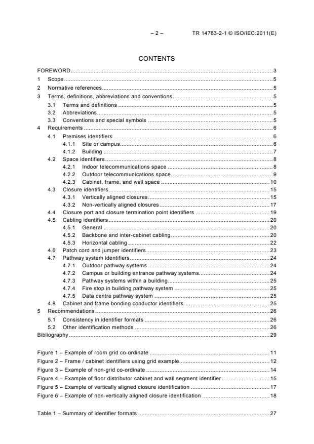
– 2 – TR 14763-2-1 © ISO/IEC:2011(E)
CONTENTS
FOREWORD . 3
1 Scope . 5
2 Normative references. 5
3 Terms, definitions, abbreviations and conventions . 5
3.1 Terms and definitions . 5
3.2 Abbreviations . 5
3.3 Conventions and special symbols . 5
4 Requirements . 6
4.1 Premises identifiers . 6
4.1.1 Site or campus . 6
4.1.2 Building . 7
4.2 Space identifiers . 8
4.2.1 Indoor telecommunications space . 8
4.2.2 Outdoor telecommunications space . 9
4.2.3 Cabinet, frame, and wall space . 10
4.3 Closure identifiers . 15
4.3.1 Vertically aligned closures . 15
4.3.2 Non-vertically aligned closures . 17
4.4 Closure port and closure termination point identifiers . 19
4.5 Cabling identifiers . 20
4.5.1 General . 20
4.5.2 Backbone and inter-cabinet cabling . 20
4.5.3 Horizontal cabling . 22
4.6 Patch cord and jumper identifiers . 23
4.7 Pathway system identifiers . 24
4.7.1 Outdoor pathway systems . 24
4.7.2 Campus or building entrance pathway systems. 24
4.7.3 Pathway systems within a building . 25
4.7.4 Fire stop in building pathway system . 25
4.7.5 Data centre pathway system . 25
4.8 Cabinet and frame bonding conductor identifiers . 25
5 Recommendations . 26
5.1 Consistency in identifier formats . 26
5.2 Other identification methods . 26
Bibliography . 29
Figure 1 – Example of room grid co-ordinate . 11
Figure 2 – Frame / cabinet identifiers using grid example. 12
Figure 3 – Example of non-grid co-ordinate . 14
Figure 4 – Example of floor distributor cabinet and wall segment identifier . 15
Figure 5 – Example of vertically aligned closure identification . 17
Figure 6 – Example of non-vertically aligned closure identification . 18
Table 1 – Summary of identifier formats . 27
TR 14763-2-1 © ISO/IEC:2011(E) – 3 –
INFORMATION TECHNOLOGY –
IMPLEMENTATION AND OPERATION
OF CUSTOMER PREMISES CABLING –
Part 2-1: Planning and installation –
Identifiers within administration systems
FOREWORD
1) ISO (International Organization for Standardization) and IEC (International Electrotechnical Commission) form
the specialized system for worldwide standardization. National bodies that are members of ISO or IEC
participate in the development of International Standards. Their preparation is entrusted to technical
committees; any ISO and IEC member body interested in the subject dealt with may participate in this
preparatory work. International governmental and non-governmental organizations liaising with ISO and IEC
also participate in this preparation.
2) In the field of information technology, ISO and IEC have established a joint technical committee,
ISO/IEC JTC 1. Draft International Standards adopted by the joint technical committee are circulated to
national bodies for voting. Publication as an International Standard requires approval by at least 75 % of the
national bodies casting a vote.
3) The formal decisions or agreements of IEC and ISO on technical matters express, as nearly as possible, an
international consensus of opinion on the relevant subjects since each technical committee has representation
from all interested IEC and ISO member bodies.
4) IEC, ISO and ISO/IEC publications have the form of recommendations for international use and are accepted
by IEC and ISO member bodies in that sense. While all reasonable efforts are made to ensure that the
technical content of IEC, ISO and ISO/IEC publications is accurate, IEC or ISO cannot be held responsible for
the way in which they are used or for any misinterpretation by any end user.
5) In order to promote international uniformity, IEC and ISO member bodies undertake to apply IEC, ISO and
ISO/IEC publications transparently to the maximum extent possible in their national and regional publications.
Any divergence between any ISO/IEC publication and the corresponding national or regional publication should
be clearly indicated in the latter.
6) ISO and IEC provide no marking procedure to indicate their approval and cannot be rendered responsible for
any equipment declared to be in conformity with an ISO/IEC publication.
7) All users should ensure that they have the latest edition of this publication.
8) No liability shall attach to IEC or ISO or its directors, employees, servants or agents including individual
experts and members of their technical committees and IEC or ISO member bodies for any personal injury,
property damage or other damage of any nature whatsoever, whether direct or indirect, or for costs (including
legal fees) and expenses arising out of the publication of, use of, or reliance upon, this ISO/IEC publication or
any other IEC, ISO or ISO/IEC publications.
9) Attention is drawn to the normative references cited in this publication. Use of the referenced publications is
indispensable for the correct application of this publication.
10) Attention is drawn to the possibility that some of the elements of this International Standard may be the subject
of patent rights. ISO and IEC shall not be held responsible for identifying any or all such patent rights.
The main task of IEC technical committees is to prepare International Standards. However, a
technical committee may propose the publication of a technical report when it has collected
data of a different kind from that which is normally published as an International Standard, for
example "state of the art".
IEC 14763-2-1, which is a technical report, has been prepared by subcommittee 25:
Interconnection of information technology equipment, of ISO/IEC joint technical committee 1:
Information technology.
The list of all currently available parts of the ISO/IEC 14763 series, under the general title
Information technology – Implementation and operation of customer premises cabling, can be
found on the IEC web site.
– 4 – TR 14763-2-1 © ISO/IEC:2011(E)
This Technical Report has been approved by vote of the member bodies, and the voting results
may be obtained from the address given on the second title page.
This publication has been drafted in accordance with the ISO/IEC Directives, Part 2.
IMPORTANT – The “colour inside” logo on the cover page of this publication indicates
that it contains colours which are considered to be useful for the correct understanding
of its contents. Users should therefore print this publication using a colour printer.
TR 14763-2-1 © ISO/IEC:2011(E) – 5 –
INFORMATION TECHNOLOGY –
IMPLEMENTATION AND OPERATION
OF CUSTOMER PREMISES CABLING –
Part 2-1: Planning and installation –
Identifiers within administration systems
1 Scope
This part of ISO/IEC 14763 contains requirements and recommendations for identification of
cabling infrastructure elements to support ISO/IEC 14763-2 and equivalent standards. The
symbols and object codes specified in this Technical Report are primarily based on
IEC 81346-1 and IEC 81346-2.
2 Normative references
The following referenced documents are indispensable for the application of this document. For
dated references, only the edition cited applies. For undated references, the latest edition of
the referenced document (including any amendments) applies.
ISO/IEC 14763-2, Information technology – Implementation and operation of customer
premises cabling – Part 2: Planning and installation
ISO 4157 (all parts), Construction drawings – Designation systems
ISO 4157-1, Construction drawings – Designation systems – Part 1: Buildings and parts of
buildings
3 Terms, definitions, abbreviations and conventions
3.1 Terms and definitions
For the purposes of this document the terms and definitions of ISO/IEC 14763-2 apply.
3.2 Abbreviations
For the purposes of this document the abbreviations of ISO/IEC 14763-2 apply.
3.3 Conventions and special symbols
Square brackets indicate optional fields. The square brackets are not part of the identifier.
Characters in italics are variables. With the exception of the square brackets, all other
characters that are not in italics are used in the identifier, as shown.
For example, the telecommunications space identifier has the format:
[[+c]+b]+[f]s
Thus, depending on the need to include the campus identifier (c), building identifier (b), or floor
(f) identifier the identifier may have the format of either
– 6 – TR 14763-2-1 © ISO/IEC:2011(E)
+c+b+fs, +b+fs, +fs, +c+b+s, +c+s, +b+s, or +s
where
s is the space identifier.
Note that the brackets for the campus identifier +c are nested within the brackets for the
building identifier +b. Thus, the campus identifier +c is only included if the building identifier +b
is also included.
The plus sign “+” is part of the identifier and specifies that the next portion of the identifier is
the location aspect of an object.
The equal sign “=“ is also used to specify a function aspect of an object (for example “=XO” for
telecommunications outlet).
The period “.” character separates the portion of the identifier for the space and the portion of
the identifier for the cabinet or frame.
The colon “:” is used as a prefix to port identifiers.
The underscore “_” character separates the vertical and horizontal coordinates of a closure in a
cabinet, frame, or wall section. In a cable identifier it is also used between the first and last
port, pair, or fibre numbers.
The forward slash “/” is used between the identifiers of the two ends of a horizontal cable,
backbone cable, or telecommunications pathway.
The back slash “\” is used between the identifiers of the two ends of a patch cord or jumper.
Additional information, such as the coordinates of a maintenance hole, conduit number within a
duct bank, or subduct number within a conduit, is enclosed in parenthesis.
4 Requirements
4.1 Premises identifiers
4.1.1 Site or campus
4.1.1.1 General
Campus or site identifiers shall use the following format:
c one or more alpha-numeric characters identifying a campus or site.
Campus and site identifiers shall be unique within a telecommunications administration system.
If a site or campus shall be identified, and no other scheme is otherwise employed by the
organization, the designation should be based on a recognised code system, for example the
IATA airport codes:
+LHR2 (for site 2 within the region served by LHR airport)
If no such code system exists or is applicable, the site or campus should use the following
designation system:
+[Ni][Ra]Ce
TR 14763-2-1 © ISO/IEC:2011(E) – 7 –
The fields are defined in the following subclauses.
Examples of identifiers for a campus (site 2) in San Francisco (area code 415) in the United
States (County Code 1) are:
+N1R415C2 or +R415C2 or +N1C2 or +C2
4.1.1.2 Nation
If the format +[Ni][Ra]Ce is used for campus/site identifiers, the country Ni shall be designated
as follows:
N letter N
i numeric characters consisting of the international dialling code for the nation.
Examples:
+N44 (for UK)
+N47 (for Norway)
4.1.1.3 Region
If the format +[Ni][Ra]Ce is used for campus/site identifiers, the region Ra should be
designated as follows:
R letter R
a numeric characters consisting of the area code or code.
NOTE There is a risk that area codes in certain countries are prone to change as telecommunications need
increase.
Examples:
+R415 (The region with the dialling code 415 within a defined country)
+R231 (The region with the dialling code 231)
4.1.1.4 Campus number
If the format +[Ni][Ra]Ce is used for campus/site identifiers, the campus Ce should be
designated as follows:
Ce is the campus or site identifier, with
C letter C
e numeric characters consisting of the campus or site number that is unique
within a given domain (i.e., region or country).
4.1.2 Building
Building identifiers shall use the following format:
[+c]+b
– 8 – TR 14763-2-1 © ISO/IEC:2011(E)
where the fields are defined as follows:
c optional field one or more alpha-numeric characters identifying a campus or
site;
b one or more alpha-numeric characters that uniquely identify the building on the
campus/site (if the campus field is used), or within the organization if no
campus/site identifier is used.
Examples:
th
+LHR2+B5 (the 5 building on the +LHR2 campus)
+HQ (a building named HQ that is not on a campus)
+NAR2 (a building with the unique name NAR2, it may be on the same campus
or region as a building named NAR1, but the campus id is omitted since
the building name is unique within the administration system)
If buildings on a site or campus need to be designated, the rules of ISO 4157-1 should be
applied.
If ISO 4157-1 is not applicable, it is recommended that the building identification scheme
described below be used:
+[Ni][Ra][Ce]Bk
Ni, Ra, and Ce are as defined in 4.1.1. Bk is defined as follows:
B letter B
k numeric characters consisting of the building number.
NOTE This is an alternative building identifier scheme that includes both the site/campus identifier as part of the
building identifier.
Examples:
th
+N44C20B4 (the 4 building on campus N44C20)
+B5 (building 5 in an administration system with no nation or region
identifiers)
4.2 Space identifiers
4.2.1 Indoor telecommunications space
Indoor telecommunications space identifiers shall have the format:
[[+c]+b]+[f]s
where the fields are defined as follows:
[+c]+b are optional and defined in 4.1.2.
TR 14763-2-1 © ISO/IEC:2011(E) – 9 –
f numeric character(s) identifying the floor of the building occupied by the space
(it may be excluded for buildings with only a single floor);
s alphanumeric character(s) uniquely identifying the telecommunications space on
floor f, or the building area in which the space is located.
For buildings with non-numeric floors, alpha-numeric characters may be used in the “f” field
and shall be consistent with the floor naming convention used within the building.
Where no other indoor space identifiers are used, the indoor space identifiers shall follow the
specifications of the ISO 4157 series.
All telecommunications space identifiers in a single infrastructure should have the same
format.
For example, the data centre on the ground floor of building +N44C20B4 may be named
+ N44C20B4+0DC
If the building had only the ground floor, the data centre could alternatively be named
+ N44C20B4+DC
The two floor distributors with room identifiers 301 and 351 in building + N44C20B4 could be
named:
+ N44C20B4+301 and + N44C20B4+351
4.2.2 Outdoor telecommunications space
Identifiers for outdoor telecommunications spaces such as maintenance holes, handholes,
joining chambers, pedestals, or outdoor cabinets shall have the format:
[+c]+T[(g)]
where
c optional field, as defined in 4.1.1 identifying the campus or site, this field is not
required if the identifiers for the outdoor telecommunications spaces U are
unique within the administration system.
T alphanumeric characters that either alone or in conjunction with the coordinates
in the (g) field uniquely identify the outdoor telecommunications space within the
site or within the administration system if the site identifier is not used.
(g) optional field with the Global Positioning System (GPS), Universal Transverse
Mercator (UTM), or map co-ordinates of the outdoor telecommunications space
in parentheses. The (g) field shall be consistently applied throughout the
administration system.
Examples:
+PED(37.797413,-122.414925) (telecommunications pedestal at GPS co-
ordinates 37.797413,-122.414925)
+SFO1+MH45 (maintenance hole 45 on campus SFO1)
– 10 – TR 14763-2-1 © ISO/IEC:2011(E)
This outdoor telecommunications space identifier may be used in place of an indoor
telecommunications space identifier [[+c]+b]+[f]s, as part of another identifier such as an
outdoor pathway identifier or outdoor cable identifier.
4.2.3 Cabinet, frame, and wall space
4.2.3.1 Rooms with grid co-ordinates
In telecommunications spaces with multiple rows of cabinets, or frames such as computer
rooms, large distributors, or telecommunications equipment rooms, it is recommended that a
grid co-ordinate system be used to identify the name and location of equipment, cabinets, and
frames.
See 4.2.3.2 for alternatives to a grid system for cabinet, frame and wall space identification.
In rooms that have access floor systems, identification for the space shall use the access floor
grid identification scheme described in this Clause. In rooms without access floor, the ceiling
tile grid, if present, should be used as the basis for space identification. If the room has neither
a floor tile grid nor a ceiling tile grid, a grid should be applied to the floor plan. The grid, if used,
shall be dense enough to ensure that two frames or cabinets do not occupy the same grid co-
ordinates – consider grid spacing between 500 mm and 600 mm (20 in to 24 in).
The quantity of characters used along the “X” and “Y” axes shall be adequate to cover the
entire space to be covered by the grid.
The “X” and “Y” axes may be reversed to minimize the quantity of characters required –
consider selecting the long axis of the room as the “X” axis and the short axis of the room as
the “Y” axis.
The starting point for the grid may be any one of the four corners of the space to be covered.
When selecting the starting point, consider the direction in which the room might be expanded.
The starting point of the grid should be in a corner of the room away from any likely direction of
room expansion.
TR 14763-2-1 © ISO/IEC:2011(E) – 11 –
‘X’ COORDINATE
AA AB AC AD AE AF AG AH AI AJ AK AL AM AN AO AP AQ AR AS AT AU AV AW AX AY AZ BA BB
‘Y’ COORDINATE
Figure 1 – Example of room grid co-ordinate
It is recommended that grid co-ordinate markings be placed on walls. Floor tiles or ceiling tiles
(if they are used as the basis of the grid) may also be marked.
A grid co-ordinate identifier shall have a format of
[[[+c]+b]+[f]s.][x]y
Note that the period “.” character separates the portion of the identifier for the space
and the portion of the identifier for the grid co-ordinate. It is not included if the optional
space identifier is omitted.
The fields are defined below.
[[[+c]+b]+[f]s] the optional telecommunications space identifier as defined in 4.2.1
is to be used when more than one space is managed by the
telecommunications administration system.
x one or more alphabetic characters designating the cabinet’s or frame’s “X” co-ordinate.
The quantity of characters used for the “X” co-ordinate shall be the same throughout the entire
space covered by the grid. Thus, as shown in
Figure 1, a space that requires between 26 and 676 co-ordinates along the “X” axis
shall start the X-axis sequence at “AA” rather than “A.” The number 676
represents the quantity of co-ordinates between AA and ZZ.
y one or more numeric characters designating the cabinet’s or frame’s “Y” co-ordinate.
The quantity of digits used for the “Y” co-ordinate shall be the same throughout the entire
space covered by the grid. Thus, as shown in
Figure 1, a space that requires more than 10 but fewer than 100 co-ordinates along the
“Y” axis shall start at “00” or “01” rather than “0” or “1”.
HOT AISLE (CABINET REAR)
COLD AISLE (CABINET FRONTS)
HOT AISLE (CABINET REAR)
– 12 – TR 14763-2-1 © ISO/IEC:2011(E)
For rooms using a grid system, it is possible that cabinets and frames will occupy more than
one grid location. In this case, the same location shall be used on every cabinet or frame to
determine the grid location. This location may be the corner closest to the starting point of the
grid, the left front corner, right front corner, or front centre as long as the same location is used
throughout the room. Following this convention allows for cabinets and frames to be substituted
or replaced with different sized items without the need to modify the identification of existing
cabinets or frames.
In the following example shown in Figure 2, the location on the floor space grid where the right
front corner of the cabinet is located, determines its identifier.
"X" COORDINATE
AA AB AC AD AE AF AG AH AI AJ
ROW AD ROW AG
AD02 AG03
AD03 AG04
AD04 AG05
AD05 AG06
AD07 AG08
AD08 AG09
AD09 AG10
AD10 AG11
AD12 AG13
= cabinet corner used for grid location ID
(right front facing the cabinet)
"Y" COORDINATE
Figure 2 – Frame / cabinet identifiers using grid example
Wall spaces in rooms using grids shall use the grid co-ordinates of the wall space. The wall
space should be divided into sections the width of each grid co-ordinate.
The grid co-ordinate system may be used to identify enclosures under access floors or in
overhead spaces in rooms that have grid co-ordinates.
In the example above in Figure 2, the cabinet whose front right corner is located at grid
location AD02 in the data centre +N1C2B4+0DC would have the identifier:
+N1C2B4+0DC.AD02
Labelling may exclude the space portion of the identifier as the location would typically be
understood by someone in the room. Thus cabinet +N1C2B4+0DC.AD02 may be labelled
AD02
TR 14763-2-1 © ISO/IEC:2011(E) – 13 –
4.2.3.2 Small rooms and rooms without grids
In rooms that are unable to utilize the grid identifier, cabinets and frames may be identified by
their row number and location within the row. This method is only recommended in spaces that
meet the following criteria:
• small number of cabinets or frames that occupy only one or two rows,
or
• uniformly spaced or static equipment rows – rows that will not be reoriented or replaced
with more or fewer rows of equipment
and
• uniform width cabinets and frames that will not be replaced by those of different width.
The quantity of characters used shall be the same throughout the space.
Where grid co-ordinates are not available, a location identifier shall have a format of
[[[+c]+b]+[f]s.]y for cabinets and frames in spaces with one equipment row,
or
[[[+c]+b]+[f]s.]xy for cabinets and frames in spaces with several equipment rows.
Note that the period “.” character separates the portion of the identifier for the space
and the portion of the identifier for the cabinet or frame. It is not included if the optional
space identifier is omitted.
The fields are defined below.
[[[+c]+b]+[f]s] the optional telecommunications space identifier as defined in 4.2.1 to
be used when more than one space is managed by the
telecommunications administration system.
x one or more characters designating the cabinet’s or frame’s row identifier. The
quantity of characters used for the row identifier should be the same throughout
the entire space. This character is optional if there is only one row in the
telecommunication space. If there are more than nine rows, it is recommended
that these characters be alphabetic instead of numeric.
y one or more characters designating the cabinet’s or frame’s location within the
row. The quantity of characters used should be the same throughout the entire
space. The location identifiers within a row should be consistent between rows,
with numbers starting from the same end and increasing in the same direction.
Figure 3 provides an example of cabinet and frame location identifiers using the non-grid
scheme (row/position method) described above.
– 14 – TR 14763-2-1 © ISO/IEC:2011(E)
A01 A02 A03 A04 A05 A06 A07 A08 A09 A10 A11 A12
ROW A ROW A
B01 B02 B03 B04 B05 B06 B07 B08 B09 B10 B11 B12
ROW B ROW B
C01 C02 C03 C04 C05 C06 C07 C08 C09 C10 C11 C12
ROW C ROW C
Figure 3 – Example of non-grid co-ordinate
Wall spaces in rooms that do not use grids should assign row identifiers to each wall on which
telecommunications equipment is mounted. The wall sp
...
Questions, Comments and Discussion
Ask us and Technical Secretary will try to provide an answer. You can facilitate discussion about the standard in here.
Loading comments...