

IEC 61010-2-020:2026
(Main)Safety requirements for electrical equipment for measurement, control, and laboratory use - Part 2-020: Particular requirements for laboratory centrifuges
- Abstract
IEC 61010-2-020:2026 is applicable to electrically powered laboratory centrifuges. It is possible that all or part of the equipment falls within the scope of one or more other Part 2 standards of IEC 61010 as well as within the scope of this document. In that case, the requirements of those other Part 2 standards will also apply. This fourth edition cancels and replaces the third edition published in 2016. This edition constitutes a technical revision.
This edition includes the following significant technical changes with respect to the previous edition:
a) alignment with changes introduced by Amendment 1:2016 of IEC 61010-1:2010.
It has the status of a product safety publication in accordance with IEC Guide 104.
This Part 2-020 is intended to be used in conjunction with the latest edition of IEC 61010-1. It was established on the basis of the third edition (2010) and its Amendment 1 (2016), hereinafter referred to as Part 1.
This Part 2-020 supplements or modifies the corresponding clauses in IEC 61010-1 so as to convert that publication into the IEC standard: Particular requirements for laboratory centrifuges.
Where a particular subclause of IEC 61010-1 is not mentioned in this Part 2-020, that subclause applies as far as is reasonable. Where this Part 2-020 states "addition", "modification" or "replacement", the relevant requirement, test specification or note in IEC 61010-1 shall be adapted accordingly.
- Status
- Published
- Publication Date
- 01-Sep-2026
- Technical Committee
- TC 66 - Safety of measuring, control and laboratory equipment
- Drafting Committee
- MT 13 - TC 66/MT 13
- Current Stage
- PPUB - Publication issued
- Start Date
- 02-Sep-2026
- Completion Date
- 22-Sep-2026
Buy Documents
REDLINE IEC 61010-2-020:2026 RLV - Safety requirements for electrical equipment for measurement, control, and laboratory use - Part 2-020: Particular requirements for laboratory centrifuges
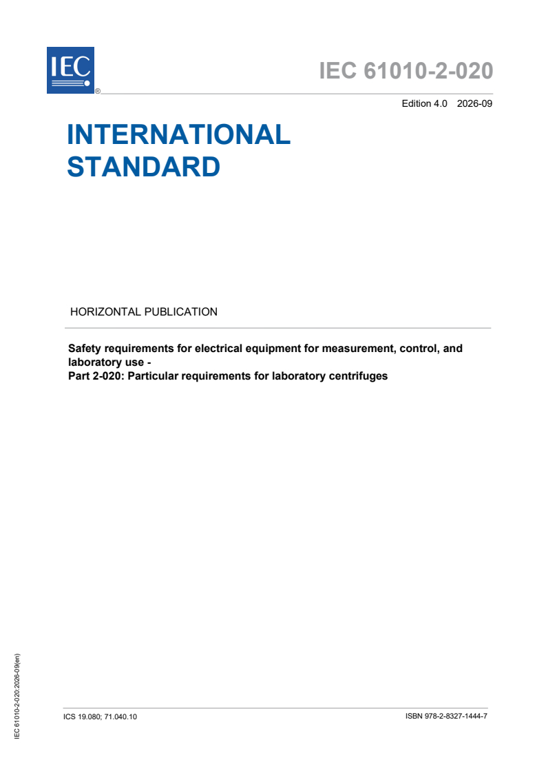
iec61010-2-020{ed4.0}en - Safety requirements for electrical equipment for measurement, control, and laboratory use - Part 2-020: Particular requirements for laboratory centrifuges
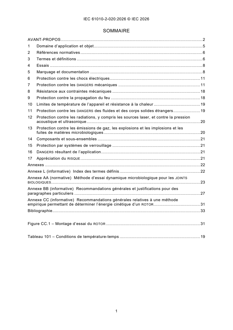
iec61010-2-020{ed4.0}fr - Exigences de sécurité pour appareils électriques de mesurage, de régulation et de laboratoire - Partie 2-020: Exigences particulieres pour centrifugeuses de laboratoire
IEC 61010-2-020:2026 is an IEC product safety publication for electrically powered laboratory centrifuges. It is intended to be used with IEC 61010-1 and adds particular safety requirements for centrifuge design, marking, tests, instructions, and risk controls. In practice, it tells manufacturers, test labs, and buyers what a laboratory centrifuge must cover for electrical, mechanical, and microbiological safety.
What does IEC 61010-2-020:2026 specify?
IEC 61010-2-020:2026 specifies particular requirements for electrically powered laboratory centrifuges. It supplements and modifies the corresponding clauses of IEC 61010-1 so that the base safety standard fits this product family.
The scope allows overlap with other IEC 61010 Part 2 standards. When part of the equipment also falls under another Part 2 standard, those requirements apply as well.
The document is organized into clauses 1 to 17, followed by Annex L, Annex AA, Annex BB, and Annex CC.
| Annex | What it covers |
|---|---|
| Annex L | Index of defined terms |
| Annex AA | Normative dynamic microbiological test method for JOINTS BIOLOGIQUES |
| Annex BB | Informative explanations and justification for selected clauses |
| Annex CC | Informative empirical method for determining rotor kinetic energy |
What are the key requirements of IEC 61010-2-020:2026?
IEC 61010-2-020:2026 focuses on the hazards that matter most for laboratory centrifuges: access to rotating parts, rotor ejection, movement during a fault, biological containment, and the information the operator needs to use the machine safely. The standard is built around IEC 61010-1, so the reader should treat Clause 1 to Clause 17 as targeted additions and changes to the general safety framework.
Marking, instructions, and declared limits
Clause 5 requires identification information, including a serial number or other production-lot identifier, and it extends the information that must be supplied for ROTORS and ACCESSOIRES DES ROTORS. The manufacturer has to identify the permitted ROTORS, their rated speeds, any material restrictions, and limits on density and load volume. For a buyer or quality manager, this means the supplied documentation must clearly define what can be used with the centrifuge and how it is to be installed and loaded.
Clause 5 also requires operating instructions for loading, balancing, rotor changing, supervision during certain phases, safe opening of the COUVERCLE, and use of JOINTS BIOLOGIQUES. It further requires cleaning, decontamination, and service instructions, including checks on mounting, protective earth continuity, CARTER DE PROTECTION condition, and biological safety components. The substance is practical: the user has to know what to inspect, what to avoid, and when additional decontamination or maintenance is needed.
Safety around moving parts and the COUVERCLE
Clause 7 is the main mechanical protection section. The COUVERCLE must normally stay locked while the rotor drive is energized and remain locked until the circumferential speed of the ENSEMBLE-ROTOR falls below 2 m/s. In practice, this is meant to prevent opening while dangerous motion remains.
An exception allows motor power interruption instead of a cover lock, but only for a tightly defined class of centrifuges with limits on speed, energy, centrifugal force, rotor diameter, and visibility of the rotor with the cover closed. If access is possible above 2 m/s, the machine must carry a warning in the form required by ISO 3864. This matters because some laboratory centrifuges are designed for observation or specialized use, but the design is still tightly bounded.
Clause 7 also requires protection against contact with moving parts of the ENSEMBLE-ROTOR and SYSTEME D’ENTRAINEMENT in normal operation and first-fault conditions. The top of the CHAMBRE must not allow a 4 mm probe to enter. That requirement gives a straightforward physical check for access control.
Stability, displacement, and PERTURBATION
Clause 7.4 requires that the centrifuge not visibly move from its installed position in normal use. Clause 7.4.101 then addresses movement caused by imbalance, PERTURBATION, or drive failure. The machine must stay within an ESPACE LIBRE of 300 mm, or a smaller value stated by the manufacturer, in all directions from its original position. For users, this means installation and floor or bench fixing are part of the safety case, not just an accessory detail.
Clause 7.7 covers ejection protection. After a PERTURBATION, fragments above 5 mm must not penetrate the CARTER DE PROTECTION, smaller material must remain within a 1 m trajectory limit, and detached parts must not create hazards. The standard allows testing against a PAE - PIRE ACCIDENT ENVISAGEABLE - and allows analytic justification only when a tested comparison basis exists. This is the part that most clearly ties design to real-world rotor failure behavior.
Biological containment and cleaning
Clause 13.101 addresses JOINTS BIOLOGIQUES. Where the manufacturer assigns such joints to a ROTOR or GODET for microbiological samples, they must prevent release of biological material when used and maintained according to the instructions, and they are verified using Annex AA. This is important for microbiology and biomedical work, where the containment claim must be demonstrated, not assumed.
Clause 11.2 and Table 101 deal with cleaning, decontamination, and steam sterilization. If the manufacturer allows steam sterilization, the part has to withstand one of the stated time-temperature conditions. For users and service teams, this means sterilization claims need to be matched to the actual component and process, especially after contamination events.
What terms does IEC 61010-2-020:2026 define?
- CENTRIFUGEUSE DE LABORATOIRE - An electrically powered device intended for laboratory use that applies centrifugal effect to sample materials.
- COMBINAISON CENTRIFUGEUSE-ROTOR - A CENTRIFUGEUSE DE LABORATOIRE and ENSEMBLE-ROTOR intended to operate together and evaluated together.
- PERTURBATION - An event in which the ENSEMBLE-ROTOR, or part of it, breaks or detaches during rotation.
- ENSEMBLE-ROTOR - A ROTOR fitted with the manufacturer-specified rotor accessories used with it.
- JOINT BIOLOGIQUE - A device or mechanism intended to prevent leakage of contents, such as microbiological material, during centrifugation.
- PAE - PIRE ACCIDENT ENVISAGEABLE, the worst foreseeable configuration chosen for safety testing.
- ESPACE LIBRE - The safety clearance space surrounding the centrifuge.
- CARTER DE PROTECTION - The enclosure that surrounds the rotor assembly and includes the COUVERCLE and its fixing means.
Who uses IEC 61010-2-020:2026?
IEC 61010-2-020:2026 is used by centrifuge manufacturers who design the machine, rotor, cover, drive, and containment system. It is also used by test laboratories and certification bodies that verify cover locking, ejection containment, cleaning resistance, and biological sealing.
In practice, quality managers, safety engineers, procurement teams, and laboratory operators use it when specifying or accepting centrifuges for diagnostic, microbiology, biomedical, and general laboratory work. It is especially relevant where rotor selection, balance, decontamination, and operator exposure are safety-critical.
What changed in IEC 61010-2-020:2026 from the previous edition?
IEC 61010-2-020:2026 is the fourth edition and cancels and replaces the third edition published in 2016. The edition is described as a technical revision.
The significant technical change stated in the document is alignment with the changes introduced by Amendment 1:2016 of IEC 61010-1:2010.
Which standards are used with IEC 61010-2-020:2026?
IEC 61010-2-020:2026 is intended to be used with IEC 61010-1, and the document is established on the basis of IEC 61010-1:2010 and IEC 61010-1:2010/AMD1:2016. Those texts provide the general safety structure that this Part 2 modifies for centrifuges.
ISO 3864 is named in the normative references and is used for safety-sign requirements where access remains possible above 2 m/s.
The text also refers to IEC 62061 and ISO 13849 as example routes for demonstrating functional safety when a sensor is used to limit movement, and it lists IEC 60034 as an excluded series for electrically rotating machines.
What does the IEC 61010-2-020:2026 document contain?
IEC 61010-2-020:2026 contains the clause-by-clause safety requirements, the defined terms, and the test and documentation rules for laboratory centrifuges. It also includes the microbiological test method in Annex AA, which uses a dynamic spore challenge to assess JOINTS BIOLOGIQUES.
Table 101 provides the time-temperature conditions for steam sterilization. Figure CC.1 shows the rotor test setup used in Annex CC, which gives an empirical method for determining rotor kinetic energy.
The document also records what evidence must be kept for PAE testing, including rotor description, test conditions, failure induction method, environment, speed at failure, damage to the CARTER DE PROTECTION, and debris release. This is the material that laboratories and conformity assessors use when they need to verify a centrifuge design rather than just describe it.
Relations
- Effective Date
- 12-Jan-2024
Buy Documents
REDLINE IEC 61010-2-020:2026 RLV - Safety requirements for electrical equipment for measurement, control, and laboratory use - Part 2-020: Particular requirements for laboratory centrifuges
iec61010-2-020{ed4.0}en - Safety requirements for electrical equipment for measurement, control, and laboratory use - Part 2-020: Particular requirements for laboratory centrifuges
iec61010-2-020{ed4.0}fr - Exigences de sécurité pour appareils électriques de mesurage, de régulation et de laboratoire - Partie 2-020: Exigences particulieres pour centrifugeuses de laboratoire
Get Certified
Connect with accredited certification bodies for this standard

ECOCERT
Organic and sustainability certification.

Eurofins Food Testing Global
Global leader in food, environment, and pharmaceutical product testing.

IMP NDT d.o.o.
Non-destructive testing services. Radiography, ultrasonic, magnetic particle, penetrant, visual inspection.
Sponsored listings
Frequently Asked Questions
IEC 61010-2-020:2026 is a standard published by the International Electrotechnical Commission (IEC). Its full title is "Safety requirements for electrical equipment for measurement, control, and laboratory use - Part 2-020: Particular requirements for laboratory centrifuges". This standard covers: IEC 61010-2-020:2026 is applicable to electrically powered laboratory centrifuges. It is possible that all or part of the equipment falls within the scope of one or more other Part 2 standards of IEC 61010 as well as within the scope of this document. In that case, the requirements of those other Part 2 standards will also apply. This fourth edition cancels and replaces the third edition published in 2016. This edition constitutes a technical revision. This edition includes the following significant technical changes with respect to the previous edition: a) alignment with changes introduced by Amendment 1:2016 of IEC 61010-1:2010. It has the status of a product safety publication in accordance with IEC Guide 104. This Part 2-020 is intended to be used in conjunction with the latest edition of IEC 61010-1. It was established on the basis of the third edition (2010) and its Amendment 1 (2016), hereinafter referred to as Part 1. This Part 2-020 supplements or modifies the corresponding clauses in IEC 61010-1 so as to convert that publication into the IEC standard: Particular requirements for laboratory centrifuges. Where a particular subclause of IEC 61010-1 is not mentioned in this Part 2-020, that subclause applies as far as is reasonable. Where this Part 2-020 states "addition", "modification" or "replacement", the relevant requirement, test specification or note in IEC 61010-1 shall be adapted accordingly.
IEC 61010-2-020:2026 is applicable to electrically powered laboratory centrifuges. It is possible that all or part of the equipment falls within the scope of one or more other Part 2 standards of IEC 61010 as well as within the scope of this document. In that case, the requirements of those other Part 2 standards will also apply. This fourth edition cancels and replaces the third edition published in 2016. This edition constitutes a technical revision. This edition includes the following significant technical changes with respect to the previous edition: a) alignment with changes introduced by Amendment 1:2016 of IEC 61010-1:2010. It has the status of a product safety publication in accordance with IEC Guide 104. This Part 2-020 is intended to be used in conjunction with the latest edition of IEC 61010-1. It was established on the basis of the third edition (2010) and its Amendment 1 (2016), hereinafter referred to as Part 1. This Part 2-020 supplements or modifies the corresponding clauses in IEC 61010-1 so as to convert that publication into the IEC standard: Particular requirements for laboratory centrifuges. Where a particular subclause of IEC 61010-1 is not mentioned in this Part 2-020, that subclause applies as far as is reasonable. Where this Part 2-020 states "addition", "modification" or "replacement", the relevant requirement, test specification or note in IEC 61010-1 shall be adapted accordingly.
IEC 61010-2-020:2026 is classified under the following ICS (International Classification for Standards) categories: 19.080 - Electrical and electronic testing; 71.040.10 - Chemical laboratories. Laboratory equipment. The ICS classification helps identify the subject area and facilitates finding related standards.
IEC 61010-2-020:2026 has the following relationships with other standards: It is inter standard links to IEC 61010-2-020:2016. Understanding these relationships helps ensure you are using the most current and applicable version of the standard.
IEC 61010-2-020:2026 is available in PDF format for immediate download after purchase. The document can be added to your cart and obtained through the secure checkout process. Digital delivery ensures instant access to the complete standard document.
Standards Content (Sample)
IEC 61010-2-020 ®
Edition 4.0 2026-09
INTERNATIONAL
STANDARD
REDLINE VERSION
HORIZONTAL PUBLICATION
Safety requirements for electrical equipment for measurement, control, and
laboratory use -
Part 2-020: Particular requirements for laboratory centrifuges
ICS 19.080; 71.040.10 ISBN 978-2-8327-1490-4
All rights reserved. Unless otherwise specified, no part of this publication may be reproduced or utilized in any form or
by any means, electronic or mechanical, including photocopying and microfilm, without permission in writing from either
IEC or IEC's member National Committee in the country of the requester. If you have any questions about IEC copyright
or have an enquiry about obtaining additional rights to this publication, please contact the address below or your local
IEC member National Committee for further information.
IEC Secretariat Tel.: +41 22 919 02 11
3, rue de Varembé info@iec.ch
CH-1211 Geneva 20 www.iec.ch
Switzerland
About the IEC
The International Electrotechnical Commission (IEC) is the leading global organization that prepares and publishes
International Standards for all electrical, electronic and related technologies.
About IEC publications
The technical content of IEC publications is kept under constant review by the IEC. Please make sure that you have the
latest edition, a corrigendum or an amendment might have been published.
IEC publications search - IEC Products & Services Portal - products.iec.ch
webstore.iec.ch/advsearchform Discover our powerful search engine and read freely all the
The advanced search enables to find IEC publications by a publications previews, graphical symbols and the glossary.
variety of criteria (reference number, text, technical With a subscription you will always have access to up to date
committee, …). It also gives information on projects, content tailored to your needs.
replaced and withdrawn publications.
Electropedia - www.electropedia.org
The world's leading online dictionary on electrotechnology,
IEC Just Published - webstore.iec.ch/justpublished
Stay up to date on all new IEC publications. Just Published containing more than 22 500 terminological entries in English
details all new publications released. Available online and and French, with equivalent terms in 25 additional languages.
once a month by email. Also known as the International Electrotechnical Vocabulary
(IEV) online.
IEC Customer Service Centre - webstore.iec.ch/csc
If you wish to give us your feedback on this publication or
need further assistance, please contact the Customer
Service Centre: sales@iec.ch.
CONTENTS
FOREWORD . 2
1 Scope and object . 4
2 Normative references . 5
3 Terms and definitions . 5
4 Tests . 7
5 Marking and documentation . 7
6 Protection against electric shock . 10
7 Protection against mechanical HAZARDS . 10
8 Mechanical resistance to shock and impact Resistance to mechanical stresses . 17
9 Protection against the spread of fire . 17
10 Equipment temperature limits and resistance to heat . 17
11 Protection against HAZARDS from fluids and solid foreign objects . 17
12 Protection against radiation, including laser sources, and against sonic and
ultrasonic pressure . 19
13 Protection against liberated gases, explosion and implosion and escape of
microbiological materials . 19
14 Components and subassemblies . 19
15 Protection by interlocks . 19
16 HAZARDS resulting from application . 19
17 RISK assessment . 19
Annexes . 20
Annex L (informative) Index of defined terms . 20
Annex AA (normative) Dynamic microbiological test method for bioseals . 22
Annex BB (informative) General guidance and rationale for particular subclauses . 25
Annex CC (informative) General guidance for an empirical method to determine the
kinetic energy of a ROTOR . 30
Bibliography . 32
Figure 101 CC.1 – ROTOR test setup . 30
Table 101 – Time-temperature conditions . 19
INTERNATIONAL ELECTROTECHNICAL COMMISSION
____________
Safety requirements for electrical equipment for
measurement, control, and laboratory use -
Part 2-020: Particular requirements for laboratory centrifuges
FOREWORD
1) The International Electrotechnical Commission (IEC) is a worldwide organization for standardization comprising
all national electrotechnical committees (IEC National Committees). The object of IEC is to promote international
co-operation on all questions concerning standardization in the electrical and electronic fields. To this end and
in addition to other activities, IEC publishes International Standards, Technical Specifications, Technical Reports,
Publicly Available Specifications (PAS) and Guides (hereafter referred to as “IEC Publication(s)”). Their
preparation is entrusted to technical committees; any IEC National Committee interested in the subject dealt with
may participate in this preparatory work. International, governmental and non-governmental organizations liaising
with the IEC also participate in this preparation. IEC collaborates closely with the International Organization for
Standardization (ISO) in accordance with conditions determined by agreement between the two organizations.
2) The formal decisions or agreements of IEC on technical matters express, as nearly as possible, an international
consensus of opinion on the relevant subjects since each technical committee has representation from all
interested IEC National Committees.
3) IEC Publications have the form of recommendations for international use and are accepted by IEC National
Committees in that sense. While all reasonable efforts are made to ensure that the technical content of IEC
Publications is accurate, IEC cannot be held responsible for the way in which they are used or for any
misinterpretation by any end user.
4) In order to promote international uniformity, IEC National Committees undertake to apply IEC Publications
transparently to the maximum extent possible in their national and regional publications. Any divergence between
any IEC Publication and the corresponding national or regional publication shall be clearly indicated in the latter.
5) IEC itself does not provide any attestation of conformity. Independent certification bodies provide conformity
assessment services and, in some areas, access to IEC marks of conformity. IEC is not responsible for any
services carried out by independent certification bodies.
6) All users should ensure that they have the latest edition of this publication.
7) No liability shall attach to IEC or its directors, employees, servants or agents including individual experts and
members of its technical committees and IEC National Committees for any personal injury, property damage or
other damage of any nature whatsoever, whether direct or indirect, or for costs (including legal fees) and
expenses arising out of the publication, use of, or reliance upon, this IEC Publication or any other IEC
Publications.
8) Attention is drawn to the Normative references cited in this publication. Use of the referenced publications is
indispensable for the correct application of this publication.
9) IEC draws attention to the possibility that the implementation of this document may involve the use of (a)
patent(s). IEC takes no position concerning the evidence, validity or applicability of any claimed patent rights in
respect thereof. As of the date of publication of this document, IEC had not received notice of (a) patent(s), which
may be required to implement this document. However, implementers are cautioned that this may not represent
the latest information, which may be obtained from the patent database available at https://patents.iec.ch. IEC
shall not be held responsible for identifying any or all such patent rights.
This redline version of the official IEC Standard allows the user to identify the changes made
to the previous edition IEC 61010-2-020:2016. A vertical bar appears in the margin wherever a
change has been made. Additions are in green text, deletions are in strikethrough red text.
IEC 61010-2-020 has been prepared by IEC technical committee 66: Safety of measuring,
control and laboratory equipment. It is an International Standard.
This fourth edition cancels and replaces the third edition published in 2016. This edition
constitutes a technical revision.
This edition includes the following significant technical changes with respect to the previous
edition:
a) alignment with changes introduced by Amendment 1:2016 of IEC 61010-1:2010.
It has the status of a product safety publication in accordance with IEC Guide 104.
The text of this International Standard is based on the following documents:
Draft Report on voting
66/820/CDV 66/868/RVC
Full information on the voting for its approval can be found in the report on voting indicated in
the above table.
The language used for the development of this International Standard is English.
This document was drafted in accordance with ISO/IEC Directives, Part 2, and developed in
accordance with ISO/IEC Directives, Part 1 and ISO/IEC Directives, IEC Supplement, available
at www.iec.ch/members_experts/refdocs. The main document types developed by IEC are
described in greater detail at www.iec.ch/publications.
This Part 2-020 is intended to be used in conjunction with the latest edition of IEC 61010-1. It
was established on the basis of the third edition (2010) and its Amendment 1 (2016), hereinafter
referred to as Part 1.
This Part 2-020 supplements or modifies the corresponding clauses in IEC 61010-1 so as to
convert that publication into the IEC standard: Particular requirements for laboratory
centrifuges.
Where a particular subclause of IEC 61010-1 is not mentioned in this Part 2-020, that subclause
applies as far as is reasonable. Where this Part 2-020 states "addition", "modification" or
"replacement", the relevant requirement, test specification or note in IEC 61010-1 shall be
adapted accordingly.
In this standard:
– the following print types are used:
• requirements: in roman type;
• NOTES: in small roman type;
• conformity and tests: in italic type;
• terms used throughout this standard which have been defined in Clause 3: SMALL ROMAN
CAPITALS.
– subclauses, tables or figures which are additional to those in IEC 61010-1 are numbered
starting from 101. Additional annexes are lettered starting from AA.
A list of all parts of the IEC 61010 series, published under the general title Safety requirements
for electrical equipment for measurement, control, and laboratory use, can be found on the IEC
website.
The committee has decided that the contents of this document will remain unchanged until the
stability date indicated on the IEC website under webstore.iec.ch in the data related to the
specific document. At this date, the document will be
– reconfirmed,
– withdrawn, or
– revised.
1 Scope and object
IEC 61010-1:2010, Clause 1 and IEC 61010-1:2010/AMD1:2016, Clause 1 apply except as
follows:
1.1.1 Scope
1.1.1 Equipment included in scope
Replacement:
This part of IEC 61010 is applicable to electrically powered LABORATORY CENTRIFUGES.
This group safety publication is primarily intended to be used as a product safety standard for
the products mentioned in the scope, but shall also be used by technical committees in the
preparation of its publications for products similar to those mentioned in the scope of this
standard, in accordance with the principles laid down in IEC Guide 104 and lSO/lEC Guide 51.
NOTE If It is possible that all or part of the equipment falls within the scope of one or more
other Part 2 standards of IEC 61010 as well as within the scope of this document, it will also
need to meet the requirements of those other Part 2 standards. In that case, the requirements
of those other Part 2 standards will also apply.
1.1.2 Equipment excluded from scope
Addition:
Add the following new item:
aa) IEC 60034 series (Rotating electrical machinery machines).
1.2 Object
1.2.1 Aspects included in scope
Addition:
Add the following new items:
aa) contact with moving parts (see 7.3);
bb) LABORATORY CENTRIFUGE movement during any DISRUPTION (see 7.34.101);
cc) high energy chemical reaction after ROTOR DISRUPTION (see 7.7.2.2 lk));
dd) ineffectiveness of BIOSEALS (see 13.101).
1.2.2 Aspects excluded from scope
Addition:
Add the following new items:
aa) additional precautions which may need to be are observed when centrifuging materials
which are flammable or explosive (see 5.4.101);
bb) additional precautions which may need to be are observed when centrifuging materials
that could react chemically with sufficient vigour to cause a HAZARD (see 5.4.101).
1.4 Environmental conditions
1.4.1 Normal environmental conditions
Replacement:
Replace item c) with the following:
c) temperature 2 °C to 40 °C;
1.4.2 Extended environmental conditions
Replacement:
Replace item c) with the following:
c) ambient temperatures below 2 °C or above 40 °C;
2 Normative references
IEC 61010-1:2010, Clause 2 and IEC 61010-1:2010/AMD1:2016, Clause 2 apply except as
follows:
Addition:
ISO 3864 (all parts), Graphical symbols - Safety colours and safety signs
3 Terms and definitions
IEC 61010-1:2010, Clause 3 applies except as follows:
3.1 Equipment and states of equipment
Addition:
Add the following new terms and definitions:
3.1.101
LABORATORY CENTRIFUGE
apparatus intended for laboratory use that applies a centrifuging effect to sample materials
3.1.102
CENTRIFUGE-ROTOR COMBINATION
LABORATORY CENTRIFUGE and ROTOR ASSEMBLY that are intended to operate together and which
have to be evaluated together
3.1.103
DISRUPTION
event in which the ROTOR ASSEMBLY, or part of it, fails or becomes detached during rotation
3.2 Parts and accessories
Addition:
Add the following new terms and definitions:
3.2.101
CHAMBER
enclosed space within a LABORATORY CENTRIFUGE in which the ROTOR ASSEMBLY rotates
3.2.102
ROTOR
primary component of a LABORATORY CENTRIFUGE which holds the material to be subjected to
centrifugal force and which is rotated by the DRIVE SYSTEM
3.2.103
BUCKET
sub-assembly of a ROTOR designed to support one or more containers
3.2.104
PROTECTIVE CASING
casing which completely surrounds the ROTOR ASSEMBLY and which includes the LID and its
securing devices
3.2.105
LID
access cover of the CHAMBER
3.2.106
ROTOR ASSEMBLY
ROTOR carrying a combination of ROTOR accessories specified by the manufacturer
Note 1 to entry: In the context of a ROTOR ASSEMBLY, ROTOR accessories include all components used with or in the
centrifuge ROTOR for the purpose of holding samples, including adaptors, BUCKETS, tubes and bottles.
3.2.107
DRIVE SYSTEM
all components of the LABORATORY CENTRIFUGE associated with the provision of torque to, or the
rotational support of, the ROTOR ASSEMBLY
3.2.108
BIOSEAL
device or mechanism additional to, or integral with, a ROTOR or BUCKET and a closure assembly,
and which is designed to prevent the escape of contents, for example microbiological material,
during centrifuging
3.5 Safety terms
Addition:
Add the following new terms and definitions:
3.5.101
CLEARANCE ENVELOPE
space around a LABORATORY CENTRIFUGE which is needed for safety
3.5.102
MCA
MAXIMUM CREDIBLE ACCIDENT
planned event chosen to represent worst-case conditions for a test that will evaluate the
inherent mechanical safety of a CENTRIFUGE-ROTOR COMBINATION
Note 1 to entry: See 7.7 and Annex BB.
4 Tests
IEC 61010-1:2010, Clause 4 and IEC 61010-1:2010/AMD1:2016, Clause 4 are applicable.
5 Marking and documentation
IEC 61010-1:2010, Clause 5 and IEC 61010-1:2010/AMD1:2016, Clause 5 apply except as
follows:
5.1.2 Identification
Replacement:
Replace item b) by the following:
b) serial number or other means to identify the production batch of the equipment.
Addition:
Add the following new item:
aa) serial number or other means to identify the production batch of the equipment.
5.1.3 MAINS supply
Addition:
Add the following note after the compliance statement.
NOTE 101 The maximum power or input current considered is usually during the acceleration phase of the ROTOR,
with any options such as cooling or heating energized.
Add the following new subclause:
5.1.101 ROTORS and accessories
All OPERATOR-replaceable ROTORS and ROTOR ASSEMBLIES, including ROTOR accessories, shall
be marked with the manufacturer's or supplier's name or registered trademark, and identification
code (such as ID code, serial number or batch number).
If components are too small, or are not suitable for such marking, the required information shall
be marked on the original packaging, as well as being stated in the documentation.
NOTE Packaging can be the outer box, an insert, etc.
If the manufacturer specifies that an individual part, for example a BUCKET, is to be fitted only
to a specific ROTOR or in specific ROTOR positions for balance or some other reason, each
BUCKET and ROTOR position should shall be identified by marking with corresponding numbers
or letters.
Conformity is checked by inspection.
5.4.2 Equipment RATINGS
Addition:
Add the following new items:
aa) a list of all ROTORS and ROTOR accessories specified for use with a LABORATORY
CENTRIFUGE, together with their RATED rotational frequencies;
bb) any restrictions by the manufacturer warning against the use of particular materials to be
centrifuged;
cc) density and volume limits for ROTOR ASSEMBLY loading and, if applicable, derating
instructions.
5.4.3 Equipment installation
Addition:
Add, after item a), the following sublist items:
i1) floor or bench area required for the CLEARANCE ENVELOPE for the intended use (see
7.4.101);
ii2) total weight of the LABORATORY CENTRIFUGE;
iii3) instructions for site preparation;
iv4) methods for levelling of the LABORATORY CENTRIFUGE;
v5) means for securing to the mounting surface;
5.4.4 Equipment operation
Addition:
Add the following new items:
aa) loading and balancing procedures;
bb) ROTOR changing procedure;
cc) any specific requirement for an OPERATOR to be present at stated phases of the
centrifuging procedure;
dd) necessary safeguards for personnel. Instructions shall include at least the following:
–1) not to lean on a LABORATORY CENTRIFUGE;
–2) not to stay within the CLEARANCE ENVELOPE longer than necessary for operational
reasons;
–3) not to deposit any potentially hazardous materials within the CLEARANCE ENVELOPE;
–4) methods for safe operation during open LID procedures (see 7.3.102.2);
ee) instructions for use of BIOSEALS and other biocontainment components, including the
proper closure techniques. These instructions shall indicate that BIOSEALS and related
components are intended to be part of biocontainment systems, as specified in
international and national biosafety guidelines. They are not to be relied on as the only
means of safeguarding workers and the environment when handling pathogenic micro-
organisms.
5.4.5 Equipment maintenance and service
Addition:
Add the following new paragraph text at the end of the subclause (before the note):
Where applicable, the instructions shall specify:
aaa) inspection of any means of fixing the equipment to the mounting surface and the
condition of the mounting surface itself;
bbb) safeguards for the OPERATOR during cleaning;
ccc) inspection of the PROTECTIVE CASING;
ddd) inspection of the ROTOR ASSEMBLY, and safety considerations;
eee) checking the continuity of the PROTECTIVE BONDING;
fff) frequency of inspection, routine maintenance and the method of replacement of BIOSEALS
and other biocontainment components.
Addition:
Add the following new subclauses:
5.4.101 Hazardous substances
The instructions for use shall state the precautions to be observed when the materials to be
used with a LABORATORY CENTRIFUGE are known to be toxic, radioactive, or contaminated with
pathogenic micro-organisms.
NOTE This information is relevant to the safety of both OPERATORS and service personnel.
The use within the LABORATORY CENTRIFUGE of the following materials shall be prohibited in the
instructions for use:
a) flammable or explosive materials;
b) materials which could react chemically with sufficient vigour to cause a HAZARD.
Conformity is checked by inspection.
5.4.102 Cleaning and decontamination
Documentation shall include:
OPERATOR
a) a statement that, if hazardous material is spilt on or inside the equipment, the user
has responsibility for carrying out appropriate decontamination;
b) manufacturer's recommendations for cleaning and, where necessary, decontaminating,
together with the recognized generic names of recommended materials for cleaning and
decontaminating;
c) the following statement:
"Before using any cleaning or decontamination methods except other than those
recommended by the manufacturer, users should shall check with the manufacturer that the
proposed method will not damage the equipment"
d) the following statement:
"Cleaning and decontamination may can be necessary as a safeguard before LABORATORY
CENTRIFUGES, ROTORS, and any accessories are maintained, repaired, or transferred.
Manufacturers may can provide a format for users the RESPONSIBLE BODY to document that
such treatment has been carried out."
NOTE Be advised, There are national guidelines and the internationally recognized "Laboratory Biosafety Manual",
published in 1993 2004 by the World Health Organization in Geneva, which gives information on decontaminants,
their use, dilutions, properties, and potential applications.
Conformity is checked by inspection.
5.4.103 Effects of chemicals and environmental influences
To ensure continued safe use of a LABORATORY CENTRIFUGE, the documentation shall identify
damage which could result from, for example:
a) the effect of chemicals;
b) environmental influences, including natural ultra-violet radiation likely to be encountered;
c) corrosion, and other weakening of construction materials that are part of the PROTECTIVE
CASING or other protective components.
Conformity is checked by inspection of the documentation and the relevant data and/or
additional testing (if needed).
6 Protection against electric shock
IEC 61010-1:2010, Clause 6 and IEC 61010-1:2010/AMD1:2016, Clause 6 are applicable.
7 Protection against mechanical HAZARDS
IEC 61010-1:2010, Clause 7 and IEC 61010-1:2010/AMD1:2016, Clause 7 apply except as
follows:
7.1 General
Addition:
Add the following new note at the end of the subclause (before the compliance statement):
NOTE 101 A DISRUPTION resulting in damage to a part of the PROTECTIVE CASING, for example a LID-locking
mechanism, is considered to be an easily noticed SINGLE FAULT CONDITION.
7.3 Moving parts
Addition:
Add the following new subclauses.
7.3.101 LID
7.3.101.1 Requirements
LID shall, unless excepted by subclause 7.3.102.2, be locked closed when the ROTOR drive
The
is energized, and shall remain locked until the circumferential velocity of the ROTOR ASSEMBLY
is not more than 2 m/s (see Annex BB).
In the event of a power failure, the LID-locking mechanism shall not release, and subsequent
release shall require the use of a TOOL.
The LID shall be held closed with sufficient strength to withstand the results of testing in
accordance with 7.7.3. Fragments produced by any DISRUPTION shall be contained as specified
in item a) of 7.7.1.
To evaluate which of the following points are appropriate for the CENTRIFUGE-ROTOR
COMBINATION under consideration, information shall be recorded showing the tests conducted
by the manufacturer or by a test facility:
a) mechanical abuse;
b) mislatching;
c) misalignment;
d) corrosion;
e) material degradation;
f) material defects;
g) vibration;
h) cleaning and decontamination;
i) environmental influences;
j) other considerations appropriate for the design.
Conformity is checked by visual inspection, by the review of recorded information, by the tests
carried out under 7.7.3, and by any further tests considered appropriate for safety.
7.3.101.2 Exception
For LABORATORY CENTRIFUGES that satisfy all the following limitations (items a) to j)), a device
which merely interrupts motor power may can be used instead of an interlock mechanism (see
Annex BB):
a) the LABORATORY CENTRIFUGE incorporates a device which holds the LID closed;
b) the device which interrupts motor power does not permit the drive motor to be energized
unless the LID is closed;
c) the rotational frequency of the ROTOR ASSEMBLY does not exceed 3 600 rpmr/min;
d) the energy at maximum rotational frequency for the highest energy ROTOR ASSEMBLY when
fully loaded does not exceed 1 kJ;
e) the maximum centrifugal force does not exceed 2,000 g;
f) the largest ROTOR ASSEMBLY diameter does not exceed 250 mm;
g) a switch is provided for disconnecting motor power, independent of the LID position;
h) the ROTOR ASSEMBLY is visible when the LID is closed, to permit observation of any rotation;
i) all ROTOR ASSEMBLIES used conform to 7.3 of Part 1 IEC 61010-1:2010, 7.3 and IEC 61010-
1:2010/AMD1:2016, 7.3;
j) if access is possible at a circumferential velocity of the ROTOR ASSEMBLY of more than 2 m/s,
a warning label in accordance with ISO 3864 is (all parts) shall be provided on or near the
access point, indicating that the LID should not be opened until rotation has stopped. Where
there is insufficient space for such a label, symbol 14 of Table 1 is considered to be an
acceptable marking.
Conformity is checked by visual inspection and by the review of data to confirm that all the
above limitations are met.
7.3.102 ROTOR ASSEMBLIES
7.3.102.1 General
If a HAZARD could result from contact with moving parts of the ROTOR ASSEMBLY or DRIVE SYSTEM
in NORMAL CONDITION or SINGLE FAULT CONDITION, suitable protective means shall be provided to
prevent OPERATOR access, except as permitted by 7.3.101.2 and 7.3.102.2.
There shall be no holes or other openings in the top of the CHAMBER which permit the penetration
of a 4 mm diameter pin.
Conformity is checked by inspection and by using the test fingers shown in Figure B.1 and
Figure B.2, and by checking openings in the top with a 4 mm diameter pin, in NORMAL CONDITION
and in SINGLE FAULT CONDITION.
The jointed test finger shown in Figure B.2 is applied in every possible position without applying
any force. If it is possible to touch a part by applying a force, the rigid test finger shown in
Figure B.1 is applied with a force of 10 N. The force is exerted against all outer surfaces,
including the bottom, by the tip of the test finger so as to avoid wedge or lever action. The finger
shall not touch any moving part that could cause a HAZARD.
7.3.102.2 ROTOR ASSEMBLIES requiring access during rotation
If the manufacturer supplies ROTOR ASSEMBLIES requiring OPERATOR interaction (e.g. zonal or
continuous-flow ROTOR ASSEMBLIES), LABORATORY CENTRIFUGES are permitted to have an
override control which allows the motor to be energized while the access LID is open, provided
that:
a) the override control allows the motor to be energized only by use of a device (which can be
a code or code-card) that makes it possible to override a protective system and functions
by means that cannot be performed using other TOOLS, or when a special guard plate allows
only limited access to the ROTOR ASSEMBLY;
b) means are provided to cancel the override function automatically when use of the ROTOR
ASSEMBLY requiring OPERATOR interaction is ended;
c) maximum speed while the LID is open is limited to 5 000 rpmr/min.
Conformity is checked by inspection.
7.4 Stability
Addition:
Add a new third paragraph as follows after the first paragraph:
No displacement of the LABORATORY CENTRIFUGE from its installed position shall be visible during
NORMAL USE.
Addition:
Add the following new subclause:
7.4.101 LABORATORY CENTRIFUGE movement during malfunction
After installation in accordance with the manufacturer's instructions, movement of a
LABORATORY CENTRIFUGE as a result of ROTOR ASSEMBLY imbalance, ROTOR ASSEMBLY
DISRUPTION, or DRIVE SYSTEM failure (seizure), shall not present a HAZARD.
Movement shall be limited either by design, or by fastening to the mounting surface, or a
combination of both, so that no part of the LABORATORY CENTRIFUGE moves outside a CLEARANCE
ENVELOPE extending 300 mm, or less if stated by the manufacturer, in any direction from the
outermost parts of the LABORATORY CENTRIFUGE in its original position (for rationale, see
Clause BB.6).
Conformity is checked by testing to confirm that the 300 mm limit, or any lower limit stated by
the manufacturer, is not exceeded in NORMAL USE and after inducing the worst-case situation
according to 7.7.2.2 for:
a) imbalance;
Use of an imbalance sensor is acceptable as a means for limiting movement, but its possible
failure should be considered when determining the worst-case condition unless examination
of the equipment and design demonstrates conclusively that the sensor will not fail. Such
sensors shall either consist of redundant circuits, be provided with a watchdog, or apply
means to ensure that the imbalance sensor system can be considered as fail safe.
As an alternative method, the reliability and design requirements can be determined by
applying, for example IEC 62061 (SIL) or ISO 13849 (PL) (all parts) or other solutions
providing equivalent functional safety.
b) DISRUPTION of the ROTOR ASSEMBLY;
c) DRIVE SYSTEM failure;
d) seizure of the DRIVE SYSTEM.
NOTE The failure mode which will produce the greatest movement can be different from the failure mode of the
MCA determined for testing the PROTECTIVE CASING in accordance with 7.7.3. See Annex CC for additional guidance
in determining the worst-case rotor conditions.
For these tests, the LABORATORY CENTRIFUGE is mounted on, or fixed to, a horizontal smooth
concrete test surface of dimensions appropriate for the size of LABORATORY CENTRIFUGE being
tested, and as specified in the manufacturer's instructions.
7.7 Expelled parts
Replacement:
Replace the existing title and text with the following new title and text.
7.7 Protection against expelled parts or projected parts
7.7.1 General
LABORATORY CENTRIFUGES shall be designed for safe operation in NORMAL USE and SINGLE FAULT
CONDITION, in SINGLE fault condition when used with ROTOR ASSEMBLIES specified by the
manufacturer.
In the event of a DISRUPTION:
a) no parts or fragments of the ROTOR ASSEMBLY exceeding 5 mm in any dimension shall
completely penetrate the PROTECTIVE CASING. Smaller material (except for aerosols and
liquids) shall remain within a trajectory extending 1 m in any direction from the outermost
parts of the LABORATORY CENTRIFUGE (see rationale in Clause BB.6);
b) no part of the LABORATORY CENTRIFUGE shall become detached or expelled in such a way as
to present a HAZARD to personnel or the environment. In the case of parts detached or
expelled from the centrifuge (not part of the ROTOR ASSEMBLY) this is to be evaluated in
accordance with Clause 17;
c) the fastenings of the access LID shall not be loosened, and there shall be no distortion which
could create an unimpeded path between any point on the ROTOR ASSEMBLY and any point
outside the LABORATORY CENTRIFUGE.
Conformity of every CENTRIFUGE-ROTOR COMBINATION specified by the manufacturer is checked
by testing as specified in 7.7.3, under MCA conditions, or by causing DISRUPTION by partially
cutting the ROTOR, or by overloading the ROTOR ASSEMBLY, or by other appropriate means. If
more than one worst-case ROTOR ASSEMBLY selection exists, each can be tested with a new
PROTECTIVE CASING.
After the tests, the criteria of items a) to c) above shall be met, and visible cracks shall be
examined to determine whether or not the PROTECTIVE CASING would have contained the ROTOR
parts irrespective of their trajectory. A questionable result shall require the test to be repeated
once only, and a further questionable result is considered to be a failure. The equipment is
checked to ensure that parts which are HAZARDOUS LIVE have not become ACCESSIBLE and that
ACCESSIBLE conductive parts do not exceed the values of 6.3.2. In the event that the test causes
the operation of an overcurrent protection device, if the device cannot be reset without operating
again, the unit is considered to have failed safe. (See rationale in BB.6.2.)
NOTE 1 Consideration should be given to the presence of temporary gaps in containment during the MCA test in
determining questionable results.
Alternatively, the safety of a CENTRIFUGE-ROTOR COMBINATION can be established by analytical
evaluation based on comparison with one of or more of the CENTRIFUGE-ROTOR COMBINATIONS
already tested, to confirm that the PROTECTIVE CASING would have passed the relevant test of
7.7.3.
NOTE 1 This test is potentially destructive to the equipment under test and can present associated hazards to
personnel and the environment.
NOTE 2 CENTRIFUGE-ROTOR COMBINATIONS designed such that satisfactory evaluation by comparison with another
CENTRIFUGE-ROTOR COMBINATION already tested cannot be made, are tested as specified in 7.7.3.
7.7.2 Considerations for MCA tests
7.7.2.1 Information to be recorded
Recorded information shall include:
a) corrosion effects to be expected;
b) material fatigue behaviour;
c) material degradation considerations, including effects of inspection, maintenance, and
component replacement schedules;
d) temperature limitation considerations;
e) material defect considerations;
BUCKET installation considerations;
f) improper
g) relevant environmental considerations;
h) relevant maximum loading considerations;
i) electrical circuit diagram and functional descriptions;
j) material specifications and technical data;
k) pre-treatment methods to induce ROTOR ASSEMBLY failure;
l) traceability of all measuring instruments used during tests;
m) any other relevant information.
Conformity is checked by inspection of documentation relating to the above items.
7.7.2.2 Considerations for worst-case conditions
All combinations of the following that are possible shall be considered:
a) ROTOR selection: the worst-case specified ROTOR ASSEMBLY or ROTOR ASSEMBLIES; (for
calculating the kinetic energy of ROTORS, refer to Annex CC);
b) rotational frequency control setting: the maximum that an OPERATOR can select;
c) supply voltage: 10 % above the maximum RATED voltage marked on the equipment;
d) ROTOR ASSEMBLY load: the maximum specified load, partial load, and no load, including state
and density of load (e.g. liquid, solid);
e) ROTOR accessories, worst-case loading of specified accessories used with or in the ROTOR
for the purpose of holding samples, including adaptors, tubes, and bottles;
f) ROTOR ASSEMBLY imbalance: the most severe condition;
g) altitude factors: the effect of reduced atmospheric pressure and density at increased altitude
on ROTOR DRIVE SYSTEMS which rely on windage to limit maximum rotational frequency (see
1.4.1 b) and 1.4.2 b)).
NOTE 1 The windage limitation can be determined by conducting a rotational frequency test in a cabinet or
room in which the pressure is controlled to 80 kPa or less, or alternatively the rotational frequency n , which
would be reached at 2 000 m altitude, can be determined from:
nn× R
where
n is the maximum rotational frequency at standard atmospheric pressure at sea-level (101 kPa);
n is the corresponding maximum rotational frequency at an atmospheric pressure equivalent to 2 000 m;
R = 1,27 (the ratio of the density of air at sea-level, to that at 2 000 m).
h) friction between the LABORATORY CENTRIFUGE or LABORATORY CENTRIFUGE feet and the
surface on which the LABORATORY CENTRIFUGE is placed;
ih) ambient temperature: the effect on components of working at any temperature in the
permitted range from 2 °C to 40 °C, or within the RATED temperature range, whichever is
larger;
ji) a combination of ROTOR ASSEMBLY and drive unit causing an instability of the dynamic
behaviour;
kj) installation as specified by the manufacturer;
lk) the possibility of high energy chemical reaction after DISRUPTION.
NOTE 2 In LABORATORY CENTRIFUGES which develop energies of the order of 275 kJ and above, and which are
refrigerated under vacuum, it is possible for a DISRUPTION to cause a chemical explosion if parts of the ROTOR
ASSEMBLY are made of reactive material, such as aluminium and titanium. An explosion can occur due to
interaction at high energies of the ROTOR ASSEMBLY fragments with refrigerants and water.
In such cases, the worst-case conditions can be achieved by the following combination of
means:
i1) disabling rotational frequency controls and limiting devices so that the highest rotational
frequency is reached;
ii2) selecting whichever ROTOR of reactive material has the highest rotational energy, and
pretreating it so as to cause a DISRUPTION. The pre-treatment shall maximize the surface
area of the resulting fragments;
iii3) adjusting the refrigeration system to have the maximum amount of refrigerant in the
evaporator which cools the CHAMBER;
iv4) loading the ROTOR ASSEMBLY with water to 80 % of its nominal capacity;
v5) running the LABORATORY CENTRIFUGE in worst-case conditions of all other unspecified
factors until a DISRUPTION occurs.
NOTE 3 Test personnel should be aware that extraordinary energy release can result from the tests where a
high-energy chemical reaction is possible after DISRUPTION. A remote bunker facility is recommended.
Conformity is checked by inspection of documentation relating to the above items.
7.7.2.3 SINGLE FAULT CONDITIONS to be considered
The following SINGLE FAULT CONDITIONS shall be considered:
a) rotational frequency control condition: whichever SINGLE FAULT CONDITION that results in the
highest rotational frequency;
b) rotational frequency limiting system: whichever SINGLE FAULT CONDITION that permits the
highest rotational frequency;
=
c) MAINS power interruption: intermittent or permanent loss of MAINS power, if either presents
a hazardous condition;
d) DRIVE SYSTEM seizure: the sudden application of the rotational energy to the frame and case
of a LABORATORY CENTRIFUGE;
e) any component failure;
f) non-quantitative SINGLE FAULT CONDITIONS:
i1) corrosion effects, for example corrosion at the bottom of a BUCKET or cavity, stress
corrosion cracking of alloys, corrosion of welds in the PROTECTIVE CASING, environmental
crazing of polymers, etc.;
ii2) material fatigue behaviour, which may affect the mode of failure;
iii3) material defects;
iv4) improper installation of a BUCKET or any other component that is fitted in a swinging
BUCKET system (e.g. the omission of a BUCKET), incorrect mounting of a BUCKET at its
pivot points, use of an incorrect BUCKET, and overloading a BUCKET;
v5) temperature effects, such as expected extremes during transportation, high ROTOR
ASSEMBLY temperatures during operation, and any necessary treatment specified by the
manufacturer.
Conformity is checked by inspection of documentation relating to the above items.
7.7.2.4 Additional considerations due to transport, normal use and ageing
The following effects shall additionally be considered:
a) corrosion effects, for example corrosion at the bottom of a BUCKET or cavity, stress corrosion
cracking of alloys, corrosion of welds in the PROTECTIVE CASING, environmental crazing of
polymers, etc.;
b) material fatigue behaviour, which can affect the mode of failure;
c) material defects;
d) improper installation of a BUCKET or any other component that is fitted in a swinging BUCKET
system (e.g. the omission of a BUCKET), incorrect mounting of a BUCKET at its pivot points,
use of an incorrect BUCKET, and overloading a BUCKET;
e) temperature effects, such as expected extremes during transportation, high ROTOR
ASSEMBLY temperatures during operation, and any necessary treatment specified by the
manufacturer.
7.7.3 Testing the PROTECTIVE CASING
For each worst-case ROTOR ASSEMBLY selection in each MCA, determined according to 7.7.2.1
to 7.7.2.3, testing as necessary shall be carried out to prove the adequacy of the PROTECTIVE
CASING, and to show that it would have contained the ROTOR parts irrespective of their trajectory.
Protective casing shall provide adequate protection. No ROTOR parts or fragments shall be
expelled from the PROTECTIVE CASING during the tests, other than those permitted by 7.7.1 a).
Testing as necessary shall be carried out for each worst-case ROTOR ASSEMBLY selection in
ea
...
IEC 61010-2-020 ®
Edition 4.0 2026-09
INTERNATIONAL
STANDARD
HORIZONTAL PUBLICATION
Safety requirements for electrical equipment for measurement, control, and
laboratory use -
Part 2-020: Particular requirements for laboratory centrifuges
ICS 19.080; 71.040.10 ISBN 978-2-8327-1444-7
All rights reserved. Unless otherwise specified, no part of this publication may be reproduced or utilized in any form or
by any means, electronic or mechanical, including photocopying and microfilm, without permission in writing from either
IEC or IEC's member National Committee in the country of the requester. If you have any questions about IEC copyright
or have an enquiry about obtaining additional rights to this publication, please contact the address below or your local
IEC member National Committee for further information.
IEC Secretariat Tel.: +41 22 919 02 11
3, rue de Varembé info@iec.ch
CH-1211 Geneva 20 www.iec.ch
Switzerland
About the IEC
The International Electrotechnical Commission (IEC) is the leading global organization that prepares and publishes
International Standards for all electrical, electronic and related technologies.
About IEC publications
The technical content of IEC publications is kept under constant review by the IEC. Please make sure that you have the
latest edition, a corrigendum or an amendment might have been published.
IEC publications search - IEC Products & Services Portal - products.iec.ch
webstore.iec.ch/advsearchform Discover our powerful search engine and read freely all the
The advanced search enables to find IEC publications by a publications previews, graphical symbols and the glossary.
variety of criteria (reference number, text, technical With a subscription you will always have access to up to date
committee, …). It also gives information on projects, content tailored to your needs.
replaced and withdrawn publications.
Electropedia - www.electropedia.org
The world's leading online dictionary on electrotechnology,
IEC Just Published - webstore.iec.ch/justpublished
Stay up to date on all new IEC publications. Just Published containing more than 22 500 terminological entries in English
details all new publications released. Available online and and French, with equivalent terms in 25 additional languages.
once a month by email. Also known as the International Electrotechnical Vocabulary
(IEV) online.
IEC Customer Service Centre - webstore.iec.ch/csc
If you wish to give us your feedback on this publication or
need further assistance, please contact the Customer
Service Centre: sales@iec.ch.
CONTENTS
FOREWORD . 2
1 Scope and object . 4
2 Normative references . 5
3 Terms and definitions . 5
4 Tests . 6
5 Marking and documentation . 7
6 Protection against electric shock . 10
7 Protection against mechanical HAZARDS . 10
8 Resistance to mechanical stresses . 16
9 Protection against the spread of fire . 16
10 Equipment temperature limits and resistance to heat . 17
11 Protection against HAZARDS from fluids and solid foreign objects . 17
12 Protection against radiation, including laser sources, and against sonic and
ultrasonic pressure . 18
13 Protection against liberated gases, explosion and implosion and escape of
microbiological materials . 18
14 Components and subassemblies . 19
15 Protection by interlocks . 19
16 HAZARDS resulting from application . 19
17 RISK assessment . 19
Annexes . 20
Annex L (informative) Index of defined terms . 20
Annex AA (normative) Dynamic microbiological test method for BIOSEALS . 21
Annex BB (informative) General guidance and rationale for particular subclauses . 24
Annex CC (informative) General guidance for an empirical method to determine the
kinetic energy of a ROTOR . 28
Bibliography . 30
Figure CC.1 – ROTOR test setup . 28
Table 101 – Time-temperature conditions . 17
INTERNATIONAL ELECTROTECHNICAL COMMISSION
____________
Safety requirements for electrical equipment for
measurement, control, and laboratory use -
Part 2-020: Particular requirements for laboratory centrifuges
FOREWORD
1) The International Electrotechnical Commission (IEC) is a worldwide organization for standardization comprising
all national electrotechnical committees (IEC National Committees). The object of IEC is to promote international
co-operation on all questions concerning standardization in the electrical and electronic fields. To this end and
in addition to other activities, IEC publishes International Standards, Technical Specifications, Technical Reports,
Publicly Available Specifications (PAS) and Guides (hereafter referred to as “IEC Publication(s)”). Their
preparation is entrusted to technical committees; any IEC National Committee interested in the subject dealt with
may participate in this preparatory work. International, governmental and non-governmental organizations liaising
with the IEC also participate in this preparation. IEC collaborates closely with the International Organization for
Standardization (ISO) in accordance with conditions determined by agreement between the two organizations.
2) The formal decisions or agreements of IEC on technical matters express, as nearly as possible, an international
consensus of opinion on the relevant subjects since each technical committee has representation from all
interested IEC National Committees.
3) IEC Publications have the form of recommendations for international use and are accepted by IEC National
Committees in that sense. While all reasonable efforts are made to ensure that the technical content of IEC
Publications is accurate, IEC cannot be held responsible for the way in which they are used or for any
misinterpretation by any end user.
4) In order to promote international uniformity, IEC National Committees undertake to apply IEC Publications
transparently to the maximum extent possible in their national and regional publications. Any divergence between
any IEC Publication and the corresponding national or regional publication shall be clearly indicated in the latter.
5) IEC itself does not provide any attestation of conformity. Independent certification bodies provide conformity
assessment services and, in some areas, access to IEC marks of conformity. IEC is not responsible for any
services carried out by independent certification bodies.
6) All users should ensure that they have the latest edition of this publication.
7) No liability shall attach to IEC or its directors, employees, servants or agents including individual experts and
members of its technical committees and IEC National Committees for any personal injury, property damage or
other damage of any nature whatsoever, whether direct or indirect, or for costs (including legal fees) and
expenses arising out of the publication, use of, or reliance upon, this IEC Publication or any other IEC
Publications.
8) Attention is drawn to the Normative references cited in this publication. Use of the referenced publications is
indispensable for the correct application of this publication.
9) IEC draws attention to the possibility that the implementation of this document may involve the use of (a)
patent(s). IEC takes no position concerning the evidence, validity or applicability of any claimed patent rights in
respect thereof. As of the date of publication of this document, IEC had not received notice of (a) patent(s), which
may be required to implement this document. However, implementers are cautioned that this may not represent
the latest information, which may be obtained from the patent database available at https://patents.iec.ch. IEC
shall not be held responsible for identifying any or all such patent rights.
IEC 61010-2-020 has been prepared by IEC technical committee 66: Safety of measuring,
control and laboratory equipment. It is an International Standard.
This fourth edition cancels and replaces the third edition published in 2016. This edition
constitutes a technical revision.
This edition includes the following significant technical changes with respect to the previous
edition:
a) alignment with changes introduced by Amendment 1:2016 of IEC 61010-1:2010.
It has the status of a product safety publication in accordance with IEC Guide 104.
The text of this International Standard is based on the following documents:
Draft Report on voting
66/820/CDV 66/868/RVC
Full information on the voting for its approval can be found in the report on voting indicated in
the above table.
The language used for the development of this International Standard is English.
This document was drafted in accordance with ISO/IEC Directives, Part 2, and developed in
accordance with ISO/IEC Directives, Part 1 and ISO/IEC Directives, IEC Supplement, available
at www.iec.ch/members_experts/refdocs. The main document types developed by IEC are
described in greater detail at www.iec.ch/publications.
This Part 2-020 is intended to be used in conjunction with the latest edition of IEC 61010-1. It
was established on the basis of the third edition (2010) and its Amendment 1 (2016), hereinafter
referred to as Part 1.
This Part 2-020 supplements or modifies the corresponding clauses in IEC 61010-1 so as to
convert that publication into the IEC standard: Particular requirements for laboratory
centrifuges.
Where a particular subclause of IEC 61010-1 is not mentioned in this Part 2-020, that subclause
applies as far as is reasonable. Where this Part 2-020 states "addition", "modification" or
"replacement", the relevant requirement, test specification or note in IEC 61010-1 shall be
adapted accordingly.
In this standard:
– the following print types are used:
• requirements: in roman type;
• NOTES: in small roman type;
• conformity and tests: in italic type;
• terms used throughout this standard which have been defined in Clause 3: SMALL ROMAN
CAPITALS.
– subclauses, tables or figures which are additional to those in IEC 61010-1 are numbered
starting from 101. Additional annexes are lettered starting from AA.
A list of all parts of the IEC 61010 series, published under the general title Safety requirements
for electrical equipment for measurement, control, and laboratory use, can be found on the IEC
website.
The committee has decided that the contents of this document will remain unchanged until the
stability date indicated on the IEC website under webstore.iec.ch in the data related to the
specific document. At this date, the document will be
– reconfirmed,
– withdrawn, or
– revised.
1 Scope and object
IEC 61010-1:2010, Clause 1 and IEC 61010-1:2010/AMD1:2016, Clause 1 apply except as
follows:
1.1 Scope
1.1.1 Equipment included in scope
Replacement:
This part of IEC 61010 is applicable to electrically powered LABORATORY CENTRIFUGES.
It is possible that all or part of the equipment falls within the scope of one or more other Part 2
standards of IEC 61010 as well as within the scope of this document. In that case, the
requirements of those other Part 2 standards will also apply.
1.1.2 Equipment excluded from scope
Addition:
Add the following new item:
aa) IEC 60034 series (Rotating electrical machines).
1.2 Object
1.2.1 Aspects included in scope
Addition:
Add the following new items:
aa) contact with moving parts (see 7.3);
bb) LABORATORY CENTRIFUGE movement during any DISRUPTION (see 7.4.101);
cc) high energy chemical reaction after ROTOR DISRUPTION (see 7.7.2.2 k));
dd) ineffectiveness of BIOSEALS (see 13.101).
1.2.2 Aspects excluded from scope
Addition:
Add the following new items:
aa) additional precautions which are observed when centrifuging materials which are
flammable or explosive (see 5.4.101);
bb) additional precautions which are observed when centrifuging materials that could react
chemically with sufficient vigour to cause a HAZARD (see 5.4.101).
1.4 Environmental conditions
1.4.1 Normal environmental conditions
Replacement:
Replace item c) with the following:
c) temperature 2 °C to 40 °C;
1.4.2 Extended environmental conditions
Replacement:
Replace item c) with the following:
c) ambient temperatures below 2 °C or above 40 °C;
2 Normative references
IEC 61010-1:2010, Clause 2 and IEC 61010-1:2010/AMD1:2016, Clause 2 apply except as
follows:
Addition:
ISO 3864 (all parts), Graphical symbols - Safety colours and safety signs
3 Terms and definitions
IEC 61010-1:2010, Clause 3 applies except as follows:
3.1 Equipment and states of equipment
Addition:
Add the following new terms and definitions:
3.1.101
LABORATORY CENTRIFUGE
apparatus intended for laboratory use that applies a centrifuging effect to sample materials
3.1.102
CENTRIFUGE-ROTOR COMBINATION
LABORATORY CENTRIFUGE and ROTOR ASSEMBLY that are intended to operate together and which
have to be evaluated together
3.1.103
DISRUPTION
event in which the ROTOR ASSEMBLY, or part of it, fails or becomes detached during rotation
3.2 Parts and accessories
Addition:
Add the following new terms and definitions:
3.2.101
CHAMBER
enclosed space within a LABORATORY CENTRIFUGE in which the ROTOR ASSEMBLY rotates
3.2.102
ROTOR
primary component of a LABORATORY CENTRIFUGE which holds the material to be subjected to
centrifugal force and which is rotated by the DRIVE SYSTEM
3.2.103
BUCKET
sub-assembly of a ROTOR designed to support one or more containers
3.2.104
PROTECTIVE CASING
casing which completely surrounds the ROTOR ASSEMBLY and which includes the LID and its
securing devices
3.2.105
LID
access cover of the CHAMBER
3.2.106
ROTOR ASSEMBLY
ROTOR carrying a combination of ROTOR accessories specified by the manufacturer
Note 1 to entry: In the context of a ROTOR ASSEMBLY, ROTOR accessories include all components used with or in the
centrifuge ROTOR for the purpose of holding samples, including adaptors, BUCKETS, tubes and bottles.
3.2.107
DRIVE SYSTEM
all components of the LABORATORY CENTRIFUGE associated with the provision of torque to, or the
rotational support of, the ROTOR ASSEMBLY
3.2.108
BIOSEAL
device or mechanism additional to, or integral with, a ROTOR or BUCKET and a closure assembly,
and which is designed to prevent the escape of contents, for example microbiological material,
during centrifuging
3.5 Safety terms
Addition:
Add the following new terms and definitions:
3.5.101
CLEARANCE ENVELOPE
space around a LABORATORY CENTRIFUGE which is needed for safety
3.5.102
MCA
MAXIMUM CREDIBLE ACCIDENT
event chosen to represent worst-case conditions for a test that will evaluate the inherent
mechanical safety of a CENTRIFUGE-ROTOR COMBINATION
Note 1 to entry: See 7.7 and Annex BB.
4 Tests
IEC 61010-1:2010, Clause 4 and IEC 61010-1:2010/AMD1:2016, Clause 4 are applicable.
5 Marking and documentation
IEC 61010-1:2010, Clause 5 and IEC 61010-1:2010/AMD1:2016, Clause 5 apply except as
follows:
5.1.2 Identification
Addition:
Add the following new item:
aa) serial number or other means to identify the production batch of the equipment.
5.1.3 MAINS supply
Addition:
Add the following note after the compliance statement.
NOTE 101 The maximum power or input current considered is usually during the acceleration phase of the ROTOR,
with any options such as cooling or heating energized.
Add the following new subclause:
5.1.101 ROTORS and accessories
All OPERATOR-replaceable ROTORS and ROTOR ASSEMBLIES, including ROTOR accessories, shall
be marked with the manufacturer's or supplier's name or registered trademark, and identification
code (such as ID code, serial number or batch number).
If components are too small, or are not suitable for such marking, the required information shall
be marked on the original packaging, as well as being stated in the documentation.
NOTE Packaging can be the outer box, an insert, etc.
If the manufacturer specifies that an individual part, for example a BUCKET, is to be fitted only
ROTOR or in specific ROTOR positions for balance or some other reason, each
to a specific
BUCKET and ROTOR position shall be identified by marking with corresponding numbers or letters.
Conformity is checked by inspection.
5.4.2 Equipment RATINGS
Addition:
Add the following new items:
aa) a list of all ROTORS and ROTOR accessories specified for use with a LABORATORY
CENTRIFUGE, together with their RATED rotational frequencies;
bb) any restrictions by the manufacturer warning against the use of particular materials to be
centrifuged;
cc) density and volume limits for ROTOR ASSEMBLY loading and, if applicable, derating
instructions.
5.4.3 Equipment installation
Addition:
Add, after item a), the following sublist items:
1) floor or bench area required for the CLEARANCE ENVELOPE for the intended use (see
7.4.101);
2) total weight of the LABORATORY CENTRIFUGE;
3) instructions for site preparation;
4) methods for levelling of the LABORATORY CENTRIFUGE;
5) means for securing to the mounting surface;
5.4.4 Equipment operation
Addition:
Add the following new items:
aa) loading and balancing procedures;
bb) ROTOR changing procedure;
cc) any specific requirement for an OPERATOR to be present at stated phases of the
centrifuging procedure;
dd) necessary safeguards for personnel. Instructions shall include at least the following:
1) not to lean on a LABORATORY CENTRIFUGE;
2) not to stay within the CLEARANCE ENVELOPE longer than necessary for operational
reasons;
3) not to deposit any potentially hazardous materials within the CLEARANCE ENVELOPE;
4) methods for safe operation during open LID procedures (see 7.3.102.2);
ee) instructions for use of BIOSEALS and other biocontainment components, including the
proper closure techniques. These instructions shall indicate that BIOSEALS and related
components are intended to be part of biocontainment systems, as specified in
international and national biosafety guidelines. They are not to be relied on as the only
means of safeguarding workers and the environment when handling pathogenic micro-
organisms.
5.4.5 Equipment maintenance and service
Addition:
Add the following new text at the end of the subclause (before the note):
Where applicable, the instructions shall specify:
a) inspection of any means of fixing the equipment to the mounting surface and the condition
of the mounting surface itself;
b) safeguards for the OPERATOR during cleaning;
c) inspection of the PROTECTIVE CASING;
d) inspection of the ROTOR ASSEMBLY, and safety considerations;
e) checking the continuity of the PROTECTIVE BONDING;
f) frequency of inspection, routine maintenance and the method of replacement of BIOSEALS
and other biocontainment components.
Addition:
Add the following new subclauses:
5.4.101 Hazardous substances
The instructions for use shall state the precautions to be observed when the materials to be
used with a LABORATORY CENTRIFUGE are known to be toxic, radioactive, or contaminated with
pathogenic micro-organisms.
NOTE This information is relevant to the safety of both OPERATORS and service personnel.
The use within the LABORATORY CENTRIFUGE of the following materials shall be prohibited in the
instructions for use:
a) flammable or explosive materials;
b) materials which could react chemically with sufficient vigour to cause a HAZARD.
Conformity is checked by inspection.
5.4.102 Cleaning and decontamination
Documentation shall include:
a) a statement that, if hazardous material is spilt on or inside the equipment, the OPERATOR
has responsibility for carrying out appropriate decontamination;
b) manufacturer's recommendations for cleaning and, where necessary, decontaminating,
together with the recognized generic names of recommended materials for cleaning and
decontaminating;
c) the following statement:
"Before using any cleaning or decontamination methods other than those recommended by
the manufacturer, user shall check with the manufacturer that the proposed method will not
damage the equipment"
d) the following statement:
"Cleaning and decontamination can be necessary as a safeguard before LABORATORY
CENTRIFUGES, ROTORS, and any accessories are maintained, repaired, or transferred.
RESPONSIBLE BODY to document that such
Manufacturers can provide a format for the
treatment has been carried out."
NOTE There are national guidelines and the internationally recognized "Laboratory Biosafety Manual", published
in 2004 by the World Health Organization in Geneva, which gives information on decontaminants, their use, dilutions,
properties, and potential applications.
Conformity is checked by inspection.
5.4.103 Effects of chemicals and environmental influences
To ensure continued safe use of a LABORATORY CENTRIFUGE, the documentation shall identify
damage which could result from, for example:
a) the effect of chemicals;
b) environmental influences, including natural ultra-violet radiation likely to be encountered;
c) corrosion, and other weakening of construction materials that are part of the PROTECTIVE
CASING or other protective components.
Conformity is checked by inspection of the documentation and the relevant data and/or
additional testing (if needed).
6 Protection against electric shock
IEC 61010-1:2010, Clause 6 and IEC 61010-1:2010/AMD1:2016, Clause 6 are applicable.
7 Protection against mechanical HAZARDS
IEC 61010-1:2010, Clause 7 and IEC 61010-1:2010/AMD1:2016, Clause 7 apply except as
follows:
7.1 General
Addition:
Add the following new note at the end of the subclause (before the compliance statement):
NOTE 101 A DISRUPTION resulting in damage to a part of the PROTECTIVE CASING, for example a LID-locking
mechanism, is considered to be an easily noticed SINGLE FAULT CONDITION.
7.3 Moving parts
Addition:
Add the following new subclauses.
7.3.101 LID
7.3.101.1 Requirements
The LID shall, unless excepted by subclause 7.3.102.2, be locked closed when the ROTOR drive
ROTOR ASSEMBLY
is energized, and shall remain locked until the circumferential velocity of the
is not more than 2 m/s (see Annex BB).
In the event of a power failure, the LID-locking mechanism shall not release, and subsequent
release shall require the use of a TOOL.
The LID shall be held closed with sufficient strength to withstand the results of testing in
accordance with 7.7.3. Fragments produced by any DISRUPTION shall be contained as specified
in item a) of 7.7.1.
To evaluate which of the following points are appropriate for the CENTRIFUGE-ROTOR
COMBINATION under consideration, information shall be recorded showing the tests conducted
by the manufacturer or by a test facility:
a) mechanical abuse;
b) mislatching;
c) misalignment;
d) corrosion;
e) material degradation;
f) material defects;
g) vibration;
h) cleaning and decontamination;
i) environmental influences;
j) other considerations appropriate for the design.
Conformity is checked by visual inspection, by the review of recorded information, by the tests
carried out under 7.7.3, and by any further tests considered appropriate for safety.
7.3.101.2 Exception
For LABORATORY CENTRIFUGES that satisfy all the following limitations (items a) to j)), a device
which merely interrupts motor power can be used instead of an interlock mechanism (see
Annex BB):
a) the LABORATORY CENTRIFUGE incorporates a device which holds the LID closed;
b) the device which interrupts motor power does not permit the drive motor to be energized
unless the LID is closed;
c) the rotational frequency of the ROTOR ASSEMBLY does not exceed 3 600 r/min;
d) the energy at maximum rotational frequency for the highest energy ROTOR ASSEMBLY when
fully loaded does not exceed 1 kJ;
e) the maximum centrifugal force does not exceed 2,000 g;
f) the largest ROTOR ASSEMBLY diameter does not exceed 250 mm;
g) a switch is provided for disconnecting motor power, independent of the LID position;
h) the ROTOR ASSEMBLY is visible when the LID is closed, to permit observation of any rotation;
i) all ROTOR ASSEMBLIES used conform to IEC 61010-1:2010, 7.3 and IEC 61010-
1:2010/AMD1:2016, 7.3;
j) if access is possible at a circumferential velocity of the ROTOR ASSEMBLY of more than 2 m/s,
a warning label in accordance with ISO 3864 (all parts) shall be provided on or near the
access point, indicating that the LID should not be opened until rotation has stopped. Where
there is insufficient space for such a label, symbol 14 of Table 1 is considered to be an
acceptable marking.
Conformity is checked by visual inspection and by the review of data to confirm that all the
above limitations are met.
7.3.102 ROTOR ASSEMBLIES
7.3.102.1 General
If a HAZARD could result from contact with moving parts of the ROTOR ASSEMBLY or DRIVE SYSTEM
in NORMAL CONDITION or SINGLE FAULT CONDITION, protective means shall be provided to prevent
OPERATOR access, except as permitted by 7.3.101.2 and 7.3.102.2.
There shall be no holes or other openings in the top of the CHAMBER which permit the penetration
of a 4 mm diameter pin.
Conformity is checked by inspection and by using the test fingers shown in Figure B.1 and
Figure B.2, and by checking openings in the top with a 4 mm diameter pin, in NORMAL CONDITION
and in SINGLE FAULT CONDITION.
The jointed test finger shown in Figure B.2 is applied in every possible position without applying
any force. If it is possible to touch a part by applying a force, the rigid test finger shown in
Figure B.1 is applied with a force of 10 N. The force is exerted against all outer surfaces,
including the bottom, by the tip of the test finger so as to avoid wedge or lever action. The finger
shall not touch any moving part that could cause a HAZARD.
7.3.102.2 ROTOR ASSEMBLIES requiring access during rotation
If the manufacturer supplies ROTOR ASSEMBLIES requiring OPERATOR interaction (e.g. zonal or
continuous-flow ROTOR ASSEMBLIES), LABORATORY CENTRIFUGES are permitted to have an
override control which allows the motor to be energized while the access LID is open, provided
that:
a) the override control allows the motor to be energized only by use of a device (which can be
a code or code-card) that makes it possible to override a protective system and functions
by means that cannot be performed using other TOOLS, or when a special guard plate allows
only limited access to the ROTOR ASSEMBLY;
b) means are provided to cancel the override function automatically when use of the ROTOR
ASSEMBLY requiring OPERATOR interaction is ended;
c) maximum speed while the LID is open is limited to 5 000 r/min.
Conformity is checked by inspection.
7.4 Stability
Addition:
Add a new paragraph after the first paragraph:
No displacement of the LABORATORY CENTRIFUGE from its installed position shall be visible during
NORMAL USE.
Addition:
Add the following new subclause:
7.4.101 LABORATORY CENTRIFUGE movement during malfunction
After installation in accordance with the manufacturer's instructions, movement of a
LABORATORY CENTRIFUGE as a result of ROTOR ASSEMBLY imbalance, ROTOR ASSEMBLY
DISRUPTION, or DRIVE SYSTEM failure (seizure), shall not present a HAZARD.
Movement shall be limited either by design, or by fastening to the mounting surface, or a
combination of both, so that no part of the LABORATORY CENTRIFUGE moves outside a CLEARANCE
ENVELOPE extending 300 mm, or less if stated by the manufacturer, in any direction from the
outermost parts of the LABORATORY CENTRIFUGE in its original position (for rationale, see
Clause BB.6).
Conformity is checked by testing to confirm that the 300 mm limit, or any lower limit stated by
the manufacturer, is not exceeded in NORMAL USE and after inducing the worst-case situation
according to 7.7.2.2 for:
a) imbalance;
Use of an imbalance sensor is acceptable as a means for limiting movement. Such sensors
shall either consist of redundant circuits, be provided with a watchdog, or apply means to
ensure that the imbalance sensor system can be considered as fail safe.
As an alternative method, the reliability and design requirements can be determined by
applying, for example IEC 62061 (SIL) or ISO 13849 (PL) (all parts) or other solutions
providing equivalent functional safety.
b) DISRUPTION of the ROTOR ASSEMBLY;
c) DRIVE SYSTEM failure;
d) seizure of the DRIVE SYSTEM.
NOTE The failure mode which will produce the greatest movement can be different from the failure mode of the
MCA determined for testing the PROTECTIVE CASING in accordance with 7.7.3. See Annex CC for additional guidance
in determining the worst-case conditions.
For these tests, the LABORATORY CENTRIFUGE is mounted on, or fixed to, a horizontal smooth
concrete test surface of dimensions appropriate for the size of LABORATORY CENTRIFUGE being
tested, and as specified in the manufacturer's instructions.
7.7 Expelled parts
Replacement:
Replace the existing title and text with the following new title and text.
7.7 Protection against expelled parts or projected parts
7.7.1 General
LABORATORY CENTRIFUGES shall be designed for safe operation in NORMAL USE and in SINGLE
fault condition when used with ROTOR ASSEMBLIES specified by the manufacturer.
DISRUPTION:
In the event of a
a) no parts or fragments of the ROTOR ASSEMBLY exceeding 5 mm in any dimension shall
completely penetrate the PROTECTIVE CASING. Smaller material (except for aerosols and
liquids) shall remain within a trajectory extending 1 m in any direction from the outermost
parts of the LABORATORY CENTRIFUGE (see rationale in Clause BB.6);
b) no part of the LABORATORY CENTRIFUGE shall become detached or expelled in such a way as
to present a HAZARD to personnel or the environment. In the case of parts detached or
expelled from the centrifuge (not part of the ROTOR ASSEMBLY) this is to be evaluated in
accordance with Clause 17;
c) the fastenings of the LID shall not be loosened, and there shall be no distortion which could
create an unimpeded path between any point on the ROTOR ASSEMBLY and any point outside
the LABORATORY CENTRIFUGE.
Conformity of every CENTRIFUGE-ROTOR COMBINATION specified by the manufacturer is checked
by testing as specified in 7.7.3, under MCA conditions, or by causing DISRUPTION by partially
cutting the ROTOR, or by overloading the ROTOR ASSEMBLY, or by other appropriate means. If
more than one worst-case ROTOR ASSEMBLY selection exists, each can be tested with a new
PROTECTIVE CASING.
After the tests, the criteria of items a) to c) above shall be met, and visible cracks shall be
examined to determine whether or not the PROTECTIVE CASING would have contained the ROTOR
parts irrespective of their trajectory. A questionable result shall require the test to be repeated
once only, and a further questionable result is considered to be a failure. The equipment is
checked to ensure that parts which are HAZARDOUS LIVE have not become ACCESSIBLE and that
ACCESSIBLE conductive parts do not exceed the values of 6.3.2. In the event that the test causes
the operation of an overcurrent protection device, if the device cannot be reset without operating
again, the unit is considered to have failed safe. (See rationale in BB.6.2.)
Alternatively, the safety of a CENTRIFUGE-ROTOR COMBINATION can be established by analytical
evaluation based on comparison with one or more of the CENTRIFUGE-ROTOR COMBINATIONS
already tested, to confirm that the PROTECTIVE CASING would have passed the relevant test of
7.7.3.
NOTE 1 This test is potentially destructive to the equipment under test and can present associated hazards to
personnel and the environment.
NOTE 2 CENTRIFUGE-ROTOR COMBINATIONS designed such that satisfactory evaluation by comparison with another
CENTRIFUGE-ROTOR COMBINATION already tested cannot be made, are tested as specified in 7.7.3.
7.7.2 Considerations for MCA tests
7.7.2.1 Information to be recorded
Recorded information shall include:
a) corrosion effects to be expected;
b) material fatigue behaviour;
c) material degradation considerations, including effects of inspection, maintenance, and
component replacement schedules;
d) temperature limitation considerations;
e) material defect considerations;
f) improper BUCKET installation considerations;
g) relevant environmental considerations;
h) relevant maximum loading considerations;
i) electrical circuit diagram and functional descriptions;
j) material specifications and technical data;
k) pre-treatment methods to induce ROTOR ASSEMBLY failure;
l) traceability of all measuring instruments used during tests;
m) any other relevant information.
7.7.2.2 Considerations for worst-case conditions
All combinations of the following that are possible shall be considered:
a) ROTOR selection: the worst-case specified ROTOR ASSEMBLY or ROTOR ASSEMBLIES; (for
calculating the kinetic energy of ROTORS, refer to Annex CC);
b) rotational frequency control setting: the maximum that an OPERATOR can select;
c) supply voltage: 10 % above the maximum RATED voltage marked on the equipment;
d) ROTOR ASSEMBLY load: the maximum specified load, partial load, and no load, including state
and density of load (e.g. liquid, solid);
e) ROTOR accessories, worst-case loading of specified accessories used with or in the ROTOR
for the purpose of holding samples, including adaptors, tubes, and bottles;
f) ROTOR ASSEMBLY imbalance: the most severe condition;
g) altitude factors: the effect of reduced atmospheric pressure and density at increased altitude
on ROTOR DRIVE SYSTEMS which rely on windage to limit maximum rotational frequency (see
1.4.1 b) and 1.4.2 b)).
NOTE 1 The windage limitation can be determined by conducting a rotational frequency test in a cabinet or
room in which the pressure is controlled to 80 kPa or less, or alternatively the rotational frequency n , which
would be reached at 2 000 m altitude, can be determined from:
nn× R
where
n is the maximum rotational frequency at standard atmospheric pressure at sea-level (101 kPa);
n is the corresponding maximum rotational frequency at an atmospheric pressure equivalent to 2 000 m;
R = 1,27 (the ratio of the density of air at sea-level, to that at 2 000 m).
h) ambient temperature: the effect on components of working at any temperature in the
permitted range from 2 °C to 40 °C, or within the RATED temperature range, whichever is
larger;
i) a combination of ROTOR ASSEMBLY and drive unit causing an instability of the dynamic
behaviour;
=
j) installation as specified by the manufacturer;
k) the possibility of high energy chemical reaction after DISRUPTION.
NOTE 2 In LABORATORY CENTRIFUGES which develop energies of the order of 275 kJ and above, and which are
refrigerated under vacuum, it is possible for a DISRUPTION to cause a chemical explosion if parts of the ROTOR
ASSEMBLY are made of reactive material, such as aluminium and titanium. An explosion can occur due to
interaction at high energies of the ROTOR ASSEMBLY fragments with refrigerants and water.
In such cases, the worst-case conditions can be achieved by the following combination of
means:
1) disabling rotational frequency controls and limiting devices so that the highest rotational
frequency is reached;
2) selecting whichever ROTOR of reactive material has the highest rotational energy, and
pretreating it so as to cause a DISRUPTION. The pre-treatment shall maximize the surface
area of the resulting fragments;
3) adjusting the refrigeration system to have the maximum amount of refrigerant in the
evaporator which cools the CHAMBER;
4) loading the ROTOR ASSEMBLY with water to 80 % of its nominal capacity;
5) running the LABORATORY CENTRIFUGE in worst-case conditions of all other unspecified
factors until a DISRUPTION occurs.
7.7.2.3 SINGLE FAULT CONDITIONS to be considered
The following SINGLE FAULT CONDITIONS shall be considered:
a) rotational frequency control condition: whichever SINGLE FAULT CONDITION that results in the
highest rotational frequency;
b) rotational frequency limiting system: whichever SINGLE FAULT CONDITION that permits the
highest rotational frequency;
c) MAINS power interruption: intermittent or permanent loss of MAINS power, if either presents
a hazardous condition;
d) DRIVE SYSTEM seizure: the sudden application of the rotational energy to the frame and case
of a LABORATORY CENTRIFUGE;
e) any component failure;
f) non-quantitative SINGLE FAULT CONDITIONS:
1) corrosion effects, for example corrosion at the bottom of a BUCKET or cavity, stress
corrosion cracking of alloys, corrosion of welds in the PROTECTIVE CASING, environmental
crazing of polymers, etc.;
2) material fatigue behaviour, which may affect the mode of failure;
3) material defects;
4) improper installation of a BUCKET or any other component that is fitted in a swinging
BUCKET system (e.g. the omission of a BUCKET), incorrect mounting of a BUCKET at its
pivot points, use of an incorrect BUCKET, and overloading a BUCKET;
5) temperature effects, such as expected extremes during transportation, high ROTOR
ASSEMBLY temperatures during operation, and any necessary treatment specified by the
manufacturer.
Conformity is checked by inspection of documentation relating to the above items.
7.7.2.4 Additional considerations due to transport, normal use and ageing
The following effects shall additionally be considered:
a) corrosion effects, for example corrosion at the bottom of a BUCKET or cavity, stress corrosion
cracking of alloys, corrosion of welds in the PROTECTIVE CASING, environmental crazing of
polymers, etc.;
b) material fatigue behaviour, which can affect the mode of failure;
c) material defects;
d) improper installation of a BUCKET or any other component that is fitted in a swinging BUCKET
system (e.g. the omission of a BUCKET), incorrect mounting of a BUCKET at its pivot points,
use of an incorrect BUCKET, and overloading a BUCKET;
e) temperature effects, such as expected extremes during transportation, high ROTOR
ASSEMBLY temperatures during operation, and any necessary treatment specified by the
manufacturer.
7.7.3 Testing the PROTECTIVE CASING
Protective casing shall provide adequate protection. No ROTOR parts or fragments shall be
expelled from the PROTECTIVE CASING during the tests, other than those permitted by 7.7.1 a).
Testing as necessary shall be carried out for each worst-case ROTOR ASSEMBLY selection in
each MCA, determined according to 7.7.2.2 to 7.7.2.4.
Each test can be carried out with a new PROTECTIVE CASING.
The ROTOR ASSEMBLY under test can first be appropriately weakened to induce it to fail during
the test of the PROTECTIVE CASING in accordance with the MCA failure mode.
Containment of an approximately half ROTOR fragment shall be taken into account when
determining an MCA, as well as other ROTOR failure modes as identified in 7.7.2.
Test data shall be recorded, including the following:
a) description of the LABORATORY CENTRIFUGE and ROTOR ASSEMBLY – model, ROTOR type,
accessories and loading;
b) MCA conditions, with justification;
c) ROTOR ASSEMBLY failure inducement method with justification;
d) date and time of the test;
e) environmental conditions during the test;
f) photographs of the LABORATORY CENTRIFUGE and relevant parts before and after the test,
with video-recording of the DISRUPTION;
g) rotational frequency at the time of ROTOR ASSEMBLY failure, and hence the energy involved;
h) type of ROTOR ASSEMBLY failure;
i) description of any damage caused to the PROTECTIVE CASING;
j) details of any movement of the LABORATORY CENTRIFUGE;
k) details of the escape of any debris.
Conformity is checked by inspection of documentation relating to the above items.
8 Resistance to mechanical stresses
IEC 61010-1:2010, Clause 8 is applicable.
9 Protection against the spread of fire
IEC 61010-1:2010, Clause 9 and IEC 61010-1:2010/AMD1:2016, Clause 9 are applicable.
10 Equipment temperature limits and resistance to heat
IEC 61010-1:2010, Clause 10 and IEC 61010-1:2010/AMD1:2016, Clause 10 are applicable.
11 Protection against HAZARDS from fluids and solid foreign objects
IEC 61010-1:2010, Clause 11 and IEC 61010-1:2010/AMD1:2016, Clause 11 apply except as
follows:
11.2 Cleaning
Replacement:
Replace the second paragraph with the following:
Conformity is checked by cleaning the equipment 20 times if a cleaning process is specified
and decontaminating the equipment once if a decontamination process is specified, in
accordance with the manufacturer’s instructions. If no restriction is given in the instructions for
use, a steam sterilization test at one of the time-temperature conditions of Table 101
(see 11.2.101) shall be repeated 20 times.
If, immediately after this tr
...
IEC 61010-2-020 ®
Edition 4.0 2026-09
NORME
INTERNATIONALE
PUBLICATION HORIZONTALE
Exigences de sécurité pour appareils électriques de mesurage, de régulation et
de laboratoire -
Partie 2-020: Exigences particulières pour centrifugeuses de laboratoire
ICS 19.080; 71.040.10 ISBN 978-2-8327-1444-7
Droits de reproduction réservés. Sauf indication contraire, aucune partie de cette publication ne peut être reproduite ni
utilisée sous quelque forme que ce soit et par aucun procédé, électronique ou mécanique, y compris la photocopie et
les microfilms, sans l'accord écrit de l'IEC ou du Comité national de l'IEC du pays du demandeur. Si vous avez des
questions sur le copyright de l'IEC ou si vous désirez obtenir des droits supplémentaires sur cette publication, utilisez
les coordonnées ci-après ou contactez le Comité national de l'IEC de votre pays de résidence.
IEC Secretariat Tel.: +41 22 919 02 11
3, rue de Varembé info@iec.ch
CH-1211 Geneva 20 www.iec.ch
Switzerland
A propos de l'IEC
La Commission Electrotechnique Internationale (IEC) est la première organisation mondiale qui élabore et publie des
Normes internationales pour tout ce qui a trait à l'électricité, à l'électronique et aux technologies apparentées.
A propos des publications IEC
Le contenu technique des publications IEC est constamment revu. Veuillez vous assurer que vous possédez l’édition la
plus récente, un corrigendum ou amendement peut avoir été publié.
Recherche de publications IEC - IEC Products & Services Portal - products.iec.ch
webstore.iec.ch/advsearchform Découvrez notre puissant moteur de recherche et consultez
La recherche avancée permet de trouver des publications gratuitement tous les aperçus des publications, symboles
IEC en utilisant différents critères (numéro de référence, graphiques et le glossaire. Avec un abonnement, vous aurez
texte, comité d’études, …). Elle donne aussi des toujours accès à un contenu à jour adapté à vos besoins.
informations sur les projets et les publications remplacées
ou retirées. Electropedia - www.electropedia.org
Le premier dictionnaire d'électrotechnologie en ligne au
IEC Just Published - webstore.iec.ch/justpublished monde, avec plus de 22 500 articles terminologiques en
Restez informé sur les nouvelles publications IEC. Just anglais et en français, ainsi que les termes équivalents
dans 25 langues additionnelles. Egalement appelé
Published détaille les nouvelles publications parues.
Disponible en ligne et une fois par mois par email. Vocabulaire Electrotechnique International (IEV) en ligne.
Service Clients - webstore.iec.ch/csc
Si vous désirez nous donner des commentaires sur cette
publication ou si vous avez des questions contactez-
nous: sales@iec.ch.
SOMMAIRE
AVANT-PROPOS . 2
1 Domaine d’application et objet . 5
2 Références normatives . 6
3 Termes et définitions . 6
4 Essais . 8
5 Marquage et documentation . 8
6 Protection contre les chocs électriques . 11
7 Protection contre les DANGERS mécaniques . 11
8 Résistance aux contraintes mécaniques . 18
9 Protection contre la propagation du feu . 18
10 Limites de température de l’appareil et résistance à la chaleur . 19
11 Protection contre les DANGERS des fluides et des corps solides étrangers . 19
12 Protection contre les radiations, y compris les sources laser, et contre la pression
acoustique et ultrasonique . 20
13 Protection contre les émissions de gaz, les explosions et les implosions et les
fuites de matières microbiologiques . 20
14 Composants et sous-ensembles . 21
15 Protection par systèmes de verrouillage . 21
16 DANGERS résultant de l’application . 21
17 Appréciation du RISQUE . 21
Annexes . 22
Annexe L (informative) Index des termes définis . 22
Annexe AA (normative) Méthode d’essai dynamique microbiologique pour les JOINTS
BIOLOGIQUES . 23
Annexe BB (informative) Recommandations générales et justifications pour des
paragraphes particuliers . 27
Annexe CC (informative) Recommandations générales relatives à une méthode
empirique permettant de déterminer l’énergie cinétique d’un ROTOR . 31
Bibliographie . 33
Figure CC.1 – Montage d’essai du ROTOR . 31
Tableau 101 – Conditions de température-temps . 19
COMMISSION ÉLECTROTECHNIQUE INTERNATIONALE
____________
Exigences de sécurité pour appareils électriques
de mesurage, de régulation et de laboratoire -
Partie 2-020: Exigences particulières pour centrifugeuses de laboratoire
AVANT-PROPOS
1) La Commission Électrotechnique Internationale (IEC) est une organisation mondiale de normalisation composée
de l’ensemble des comités électrotechniques nationaux (Comités nationaux de l’IEC). L’IEC a pour objet de
favoriser la coopération internationale pour toutes les questions de normalisation dans les domaines de
l’électricité et de l’électronique. À cet effet, l’IEC – entre autres activités – publie des Normes internationales,
des Spécifications techniques, des Rapports techniques, des Spécifications accessibles au public (PAS) et des
Guides (ci-après dénommés "Publication(s) de l’IEC"). Leur élaboration est confiée à des comités d’études, aux
travaux desquels tout Comité national intéressé par le sujet traité peut participer. Les organisations
internationales, gouvernementales et non gouvernementales, en liaison avec l’IEC, participent également aux
travaux. L’IEC collabore étroitement avec l’Organisation Internationale de Normalisation (ISO), selon des
conditions fixées par accord entre les deux organisations.
2) Les décisions ou accords officiels de l’IEC concernant les questions techniques représentent, dans la mesure du
possible, un accord international sur les sujets étudiés, étant donné que les Comités nationaux de l’IEC intéressés
sont représentés dans chaque comité d’études.
3) Les Publications de l’IEC se présentent sous la forme de recommandations internationales et sont agréées
comme telles par les Comités nationaux de l’IEC. Tous les efforts raisonnables sont entrepris afin que l’IEC
s’assure de l’exactitude du contenu technique de ses publications; l’IEC ne peut pas être tenue responsable de
l’éventuelle mauvaise utilisation ou interprétation qui en est faite par un quelconque utilisateur final.
4) Dans le but d’encourager l’uniformité internationale, les Comités nationaux de l’IEC s’engagent, dans toute la
mesure possible, à appliquer de façon transparente les Publications de l’IEC dans leurs publications nationales
et régionales. Toutes divergences entre toutes Publications de l’IEC et toutes publications nationales ou
régionales correspondantes doivent être indiquées en termes clairs dans ces dernières.
5) L’IEC elle-même ne fournit aucune attestation de conformité. Des organismes de certification indépendants
fournissent des services d’évaluation de conformité et, dans certains secteurs, accèdent aux marques de
conformité de l’IEC. L’IEC n’est responsable d’aucun des services effectués par les organismes de certification
indépendants.
6) Tous les utilisateurs doivent s’assurer qu’ils sont en possession de la dernière édition de cette publication.
7) Aucune responsabilité ne doit être imputée à l’IEC, à ses administrateurs, employés, auxiliaires ou mandataires,
y compris ses experts particuliers et les membres de ses comités d’études et des Comités nationaux de l’IEC,
pour tout préjudice causé en cas de dommages corporels et matériels, ou de tout autre dommage de quelque
nature que ce soit, directe ou indirecte, ou pour supporter les coûts (y compris les frais de justice) et les dépenses
découlant de la publication ou de l’utilisation de cette Publication de l’IEC ou de toute autre Publication de l’IEC,
ou au crédit qui lui est accordé.
8) L’attention est attirée sur les références normatives citées dans cette publication. L’utilisation de publications
référencées est obligatoire pour une application correcte de la présente publication.
9) L’IEC attire l’attention sur le fait que la mise en application du présent document peut entraîner l’utilisation d’un
ou de plusieurs brevets. L’IEC ne prend pas position quant à la preuve, à la validité et à l’applicabilité de tout
droit de brevet revendiqué à cet égard. À la date de publication du présent document, l’IEC n’avait pas reçu
notification qu’un ou plusieurs brevets pouvaient être nécessaires à sa mise en application. Toutefois, il y a lieu
d’avertir les responsables de la mise en application du présent document que des informations plus récentes
sont susceptibles de figurer dans la base de données de brevets, disponible à l’adresse https://patents.iec.ch.
L’IEC ne saurait être tenue pour responsable de ne pas avoir identifié de tels droits de brevets et de ne pas avoir
signalé leur existence.
La Norme internationale IEC 61010-2-020 a été établie par le comité d’études 66 de l’IEC:
Sécurité des appareils de mesure, de commande et de laboratoire. Il s’agit d’une Norme
internationale.
Cette quatrième édition annule et remplace la troisième édition parue en 2016. Cette édition
constitue une révision technique.
Cette édition inclut les modifications techniques majeures suivantes par rapport à l’édition
précédente:
a) alignement sur les modifications introduites dans l’Amendement 1:2016 de
l’IEC 61010-1:2010.
Elle a le statut d’une publication de sécurité de produit conformément au Guide IEC 104.
Le texte de cette Norme internationale est issu des documents suivants:
Projet Rapport de vote
66/820/CDV 66/868/RVC
Le rapport de vote indiqué dans le tableau ci-dessus donne toute information sur le vote ayant
abouti à son approbation.
La langue employée pour l’élaboration de cette Norme internationale est l’anglais.
Ce document a été rédigé selon les Directives ISO/IEC, Partie 2, il a été développé selon les
Directives ISO/IEC, Partie 1 et les Directives ISO/IEC, Supplément IEC, disponibles sous
www.iec.ch/members_experts/refdocs. Les principaux types de documents développés par
l’IEC sont décrits plus en détail sous www.iec.ch/publications.
La présente Partie 2-020 est destinée à être utilisée conjointement avec la dernière édition de
l’IEC 61010-1. Elle a été établie sur la base de la troisième édition (2010) et de son
Amendement 1 (2016), ci-après désignés Partie 1.
La présente Partie 2-020 complète ou modifie les articles correspondants de l’IEC 61010-1, de
façon à transformer cette publication en norme IEC: Exigences particulières pour
centrifugeuses de laboratoire.
Lorsqu’un paragraphe particulier de la Partie 1 n’est pas mentionné dans cette Partie 2-020,
ce paragraphe s’applique pour autant que cela soit raisonnable. Lorsque cette Partie 2-020
spécifie "addition", "modification" ou "remplacement", l’exigence correspondante,
la spécification d’essai correspondante ou la note correspondante de la Partie 1 doit être
adaptée en conséquence.
Dans la présente norme:
– les caractères d’imprimerie suivants sont utilisés:
• exigences: caractères romains;
• NOTES: petits caractères romains;
• conformité et essais: caractères italiques;
• termes utilisés tout au long de la présente norme et définis à l’Article 3: PETITES
CAPITABLES EN CARACTERES ROMAINS;
– les paragraphes, tableaux ou figures qui s’ajoutent à ceux de la Partie 1 sont numérotés à
partir de 101. Les annexes supplémentaires sont numérotées à partir de AA.
Une liste de toutes les parties de la série IEC 61010, publiées sous le titre général Exigences
de sécurité pour appareils électriques de mesurage, de régulation et de laboratoire, peut être
consultée sur le site web de l’IEC.
Le comité a décidé que le contenu de ce document ne sera pas modifié avant la date de stabilité
indiquée sur le site web de l’IEC sous webstore.iec.ch dans les données relatives au document
recherché. À cette date, le document sera
– reconduit,
– supprimé, ou
– révisé.
1 Domaine d’application et objet
L’IEC 61010-1:2010, Article 1 et l’IEC 61010-1:2010/AMD1:2016, Article 1, s’appliquent avec
les exceptions suivantes:
1.1 Domaine d’application
1.1.1 Appareils inclus dans le domaine d’application
Remplacement:
La présente partie de l’IEC 61010 s’applique aux CENTRIFUGEUSES DE LABORATOIRE alimentées
en énergie électrique.
Il est possible qu’une ou toutes les parties de l’appareil relèvent du domaine d’application d’une
ou plusieurs autres Parties 2 de l’IEC 61010, ainsi que du domaine d’application du présent
document. Si tel est le cas, les exigences de ces autres Parties 2 s’appliquent également.
1.1.2 Appareils exclus du domaine d’application
Addition:
Ajouter le nouveau point suivant:
aa) la série IEC 60034 (Machines électriques tournantes).
1.2 Objet
1.2.1 Aspects inclus dans le domaine d’application
Addition:
Ajouter les nouveaux points suivants:
aa) contact avec des parties mobiles (voir 7.3);
bb) déplacement de la CENTRIFUGEUSE DE LABORATOIRE pendant une PERTURBATION
(voir 7.4.101);
cc) réaction chimique à énergie élevée après une PERTURBATION de ROTOR (voir 7.7.2.2 k));
dd) inefficacité du JOINT BIOLOGIQUE (voir 13.101).
1.2.2 Aspects exclus du domaine d’application
Addition:
Ajouter les nouveaux points suivants:
aa) les précautions additionnelles qui sont observées lors de la centrifugation des matériaux
qui sont inflammables ou explosifs (voir 5.4.101);
bb) les précautions additionnelles qui sont observées lors de la centrifugation des matériaux
pouvant réagir chimiquement avec une force suffisante pour provoquer un DANGER
(voir 5.4.101).
1.4 Conditions d’environnement
1.4.1 Conditions d’environnement normales
Remplacement:
Remplacer le point c) par le suivant:
c) température de 2 °C à 40 °C;
1.4.2 Conditions d’environnement étendues
Remplacement:
Remplacer le point c) par le suivant:
c) températures ambiantes inférieures à 2 °C ou supérieures à 40 °C;
2 Références normatives
L’IEC 61010-1:2010, Article 2 et l’IEC 61010-1:2010/AMD1:2016, Article 2, s’appliquent avec
les exceptions suivantes:
Addition:
ISO 3864 (toutes les parties), Symboles graphiques – Couleurs de sécurité et signaux de
sécurité
3 Termes et définitions
L’IEC 61010-1:2010, Article 3 s’applique avec les exceptions suivantes:
3.1 Appareils et états des appareils
Addition:
Ajouter les nouveaux termes et définitions suivants:
3.1.101
CENTRIFUGEUSE DE LABORATOIRE
appareil prévu pour l’utilisation en laboratoire qui applique un effet de centrifugation aux
matériaux d’échantillons
3.1.102
COMBINAISON CENTRIFUGEUSE-ROTOR
CENTRIFUGEUSE DE LABORATOIRE et ENSEMBLE-ROTOR, destinés à fonctionner ensemble, et qui
doivent être évalués ensemble
3.1.103
PERTURBATION
évènement au cours duquel l’ENSEMBLE-ROTOR, ou une partie de ce dernier, se casse ou se
détache pendant la rotation
3.2 Parties et accessoires
Addition:
Ajouter les nouveaux termes et définitions suivants:
3.2.101
CHAMBRE
espace fermé contenu dans une CENTRIFUGEUSE DE LABORATOIRE dans lequel l’ENSEMBLE-ROTOR
tourne
3.2.102
ROTOR
composant primaire d’une CENTRIFUGEUSE DE LABORATOIRE qui retient le matériau à soumettre
à la force centrifuge et qui est mis en rotation par le SYSTEME D’ENTRAINEMENT
3.2.103
GODET
accessoire du ROTOR conçu pour maintenir un ou plusieurs conteneurs
3.2.104
CARTER DE PROTECTION
carter qui entoure complètement l’ENSEMBLE-ROTOR et qui comprend le COUVERCLE et ses
moyens de fixation
3.2.105
COUVERCLE
composant mobile qui permet d’accéder à la CHAMBRE
3.2.106
ENSEMBLE-ROTOR
ROTOR équipé d’un ensemble d’accessoires du ROTOR spécifiés par le constructeur
Note 1 à l’article: Dans le contexte d’un ENSEMBLE-ROTOR, les accessoires du ROTOR incluent tous les composants
utilisés avec ou dans le ROTOR de centrifugeuse afin de tenir des échantillons, y compris des adaptateurs, des
GODETS, des tubes et des bouteilles.
3.2.107
SYSTEME D’ENTRAINEMENT
tous les composants de la CENTRIFUGEUSE DE LABORATOIRE associés à l’application d’un couple
à, ou au support de rotation de, l’ENSEMBLE-ROTOR
3.2.108
JOINT BIOLOGIQUE
dispositif ou mécanisme complémentaire à un ROTOR ou à un GODET et un ensemble de
fermeture, ou qui en fait partie intégrante, et qui est conçu pour empêcher la fuite du contenu,
par exemple de matières microbiologiques, pendant la centrifugation
3.5 Termes de sécurité
Addition:
Ajouter les nouveaux termes et définitions suivants:
3.5.101
ESPACE LIBRE
espace entourant une CENTRIFUGEUSE DE LABORATOIRE, nécessaire à la sécurité
3.5.102
PAE
PIRE ACCIDENT ENVISAGEABLE
configuration choisie pour représenter le cas le plus défavorable pour un essai, dont le but est
d’évaluer la sécurité mécanique inhérente à une COMBINAISON CENTRIFUGEUSE-ROTOR
Note 1 à l’article: Voir 7.7 et l’Annexe BB.
4 Essais
L’IEC 61010-1:2010, Article 4 et l’IEC 61010-1:2010/AMD1:2016, Article 4, s’appliquent.
5 Marquage et documentation
L’article de la Partie 1 s’applique avec les exceptions suivantes.
5.1.2 Identification
Addition:
Ajouter le nouveau point suivant:
aa) du numéro de série ou tout autre moyen permettant d’identifier le lot de production de
l’appareil.
5.1.3 Alimentation RESEAU
Addition:
Ajouter la note suivante après la déclaration de conformité:
NOTE 101 La puissance maximale ou le courant d’entrée pris en considération est généralement celui de la phase
d’accélération du ROTOR, avec toute option telle que le refroidissement ou le chauffage sous tension.
Ajouter le nouveau paragraphe suivant:
5.1.101 ROTORS et accessoires
Tous les ROTORS et ENSEMBLES-ROTORS, y compris les ACCESSOIRES DES ROTORS, qui peuvent
être remplacés par un OPERATEUR doivent être marqués du nom ou de la marque déposée du
constructeur ou du fournisseur, et comporter le code d’identification (tel qu’un code ID,
un numéro de série ou un numéro de lot).
Si les composants sont trop petits ou ne sont pas appropriés pour porter ce genre de marquage,
les informations exigées doivent être marquées sur l’emballage d’origine, et également
mentionnées dans la documentation.
NOTE L’emballage peut être la boîte contenant l’appareil, les éléments ou la documentation qu’elle contient, etc.
Si le constructeur spécifie qu’une partie, par exemple un GODET, doit être montée uniquement
sur certains types de ROTORS ou dans des positions particulières du ROTOR pour des raisons
d’équilibre ou autres, chaque position respective du GODET et du ROTOR doit être identifiée par
un marquage comportant les chiffres ou les lettres correspondants.
La conformité est vérifiée par examen.
5.4.2 CARACTERISTIQUES ASSIGNEES des appareils
Addition:
Ajouter les nouveaux points suivants:
aa) une liste de tous les ROTORS et accessoires de ROTORS indiqués pour être utilisés avec
une CENTRIFUGEUSE DE LABORATOIRE, ainsi que leurs vitesses de rotation ASSIGNEES;
bb) toutes les restrictions définies par le constructeur, concernant l’interdiction de centrifuger
certaines matières;
cc) les limites de densité et de volume, de même que les instructions pour la réduction de
charge de l’ENSEMBLE-ROTOR, le cas échéant.
5.4.3 Installation des appareils
Addition:
Ajouter, après le point a), les points de sous-liste suivants:
1) la superficie du plancher ou de l’établi nécessaire pour l’ESPACE LIBRE pour l’utilisation
prévue (voir 7.4.101);
2) le poids total de la CENTRIFUGEUSE DE LABORATOIRE;
3) les instructions pour la préparation du site;
4) les méthodes pour la mise à niveau de la CENTRIFUGEUSE DE LABORATOIRE;
5) les moyens de fixation sur la surface de montage;
5.4.4 Fonctionnement de l’appareil
Addition:
Ajouter les nouveaux points suivants:
aa) les procédures de chargement et d’équilibrage;
bb) les procédures de changement de ROTOR;
cc) toute exigence spécifique pour qu’un OPÉRATEUR soit présent aux phases indiquées de la
procédure de centrifugation;
dd) les moyens de sécurité nécessaires pour le personnel. Les instructions doivent indiquer
au moins les informations suivantes:
1) ne pas se pencher sur une CENTRIFUGEUSE DE LABORATOIRE;
2) ne pas rester à l’intérieur de l’ESPACE LIBRE plus longtemps que nécessaire pour des
raisons de service;
3) ne pas déposer de matières potentiellement dangereuses à l’intérieur de l’ESPACE
LIBRE;
4) les méthodes pour le fonctionnement en toute sécurité pendant les procédures
d’ouverture de COUVERCLE (voir 7.3.102.2);
ee) les instructions pour l’utilisation des JOINTS BIOLOGIQUES et autres composants de sécurité
biologique, y compris les bonnes techniques de fermeture. Ces instructions doivent
indiquer que les JOINTS BIOLOGIQUES et leurs composants sont destinés à faire partie des
systèmes de sécurité biologique, comme cela est spécifié dans les lignes directrices de
biosécurité nationales et internationales. Elles ne doivent pas être considérées comme
les seuls moyens de protéger les travailleurs et l’environnement durant la manipulation
de micro-organismes pathogènes.
5.4.5 Entretien de l’appareil et service
Addition:
Ajouter le nouveau texte suivant à la fin du paragraphe (avant la note):
Lorsqu’elles sont applicables, les instructions doivent spécifier:
a) l’examen des moyens de fixation de l’appareil à la surface de montage ainsi que l’état de la
surface de montage elle-même;
b) les mesures de protection de l'OPÉRATEUR pendant le nettoyage;
c) l’examen du CARTER DE PROTECTION;
d) l’examen de l’ENSEMBLE-ROTOR et les aspects concernant la sécurité;
e) l’examen de la continuité de la LIAISON DE PROTECTION;
f) la fréquence d’examen, l’entretien périodique et la méthode de remplacement des JOINTS
BIOLOGIQUES et autres composants de la sécurité biologique.
Addition:
Ajouter les nouveaux paragraphes suivants:
5.4.101 Substances dangereuses
Les instructions d’utilisation doivent indiquer les précautions à observer lorsque les matières à
utiliser dans une CENTRIFUGEUSE DE LABORATOIRE sont réputées toxiques, radioactives,
ou lorsqu’elles sont contaminées par des micro-organismes pathogènes.
NOTE Cette information concerne à la fois la sécurité des OPERATEURS et celle du personnel de service.
L’utilisation des matières suivantes dans la CENTRIFUGEUSE DE LABORATOIRE doit être interdite
dans les instructions d’utilisation:
a) les matières inflammables ou explosives;
b) les matières qui peuvent réagir chimiquement avec une force suffisante pour causer un
DANGER.
La conformité est vérifiée par examen.
5.4.102 Nettoyage et décontamination
La documentation doit indiquer:
a) que l’OPERATEUR a la responsabilité d’effectuer la décontamination appropriée si la matière
dangereuse s’est répandue sur ou à l’intérieur de l’appareil;
b) les recommandations du constructeur pour le nettoyage et, si nécessaire, la
décontamination, avec les noms génériques reconnus des matériaux recommandés pour le
nettoyage et la décontamination;
c) la déclaration suivante:
"L’utilisateur ne doit pas utiliser de méthodes de nettoyage ou de décontamination
différentes de celles recommandées par le constructeur, sans au préalable vérifier auprès
du constructeur que les méthodes proposées ne risquent pas d’endommager l’appareil"
d) la déclaration suivante:
"Le nettoyage et la décontamination peuvent s’avérer nécessaires à titre préventif avant
LES CENTRIFUGEUSES DE LABORATOIRE, LES ROTORS et autres accessoires soient
que
entretenus, réparés ou transférés. Les constructeurs peuvent fournir un format permettant
ORGANISME RESPONSABLE de documenter la réalisation de ce traitement."
à l’
NOTE À noter que des lignes directrices nationales et le document "Laboratory Biosafety Manual" (Manuel de
Sécurité Biologique pour Laboratoires) reconnu au niveau international, publié en 2004 par l’Organisation mondiale
de la santé à Genève, donnent des informations sur les décontaminants, leur utilisation, leurs dilutions, leurs
propriétés et les applications potentielles.
La conformité est vérifiée par examen.
5.4.103 Effets des produits chimiques et des influences environnementales
Pour utiliser en toute sécurité et régulièrement une CENTRIFUGEUSE DE LABORATOIRE,
la documentation doit mentionner les dommages qui peuvent résulter, par exemple:
a) de l’effet des produits chimiques,
b) des influences de l’environnement, y compris de l’action des rayons ultraviolets naturels
susceptibles d’être rencontrés;
c) de la corrosion, et d’autres fragilisations des matériaux de construction entrant dans la
composition du CARTER DE PROTECTION ou d’autres composants de protection.
La conformité est vérifiée par examen de la documentation et des données appropriées et/ou
par des essais complémentaires (le cas échéant).
6 Protection contre les chocs électriques
L’IEC 61010-1:2010, Article 6 et l’IEC 61010-1:2010/AMD1:2016, Article 6, s’appliquent.
7 Protection contre les DANGERS mécaniques
L’IEC 61010-1:2010, Article 7 et l’IEC 61010-1:2010/AMD1:2016, Article 7, s’appliquent avec
les exceptions suivantes:
7.1 Généralités
Addition:
Ajouter la nouvelle note suivante à la fin du paragraphe (avant la déclaration de conformité):
NOTE 101 Une PERTURBATION entraînant des dommages sur une partie du CARTER DE PROTECTION, par exemple un
mécanisme de verrouillage du COUVERCLE, est considérée comme une condition de premier défaut aisément
identifiée.
7.3 Parties mobiles
Addition:
Ajouter les nouveaux paragraphes suivants:
7.3.101 COUVERCLE
7.3.101.1 Exigences
Le COUVERCLE doit, sauf spécification contraire en 7.3.102.2, être verrouillé en position fermée
lorsque l’entraînement du ROTOR est alimenté et doit rester verrouillé jusqu’à ce que la vitesse
circonférentielle de l’ENSEMBLE-ROTOR ne dépasse pas 2 m/s (voir Annexe BB).
Dans l’éventualité d’une panne d’alimentation, le mécanisme de verrouillage du COUVERCLE ne
doit pas se débloquer et tout déverrouillage ultérieur doit nécessiter l’utilisation d’un OUTIL.
Le COUVERCLE doit être maintenu fermé avec une force suffisante pour résister aux résultats
des essais conformément au 7.7.3. Les fragments produits par la PERTURBATION doivent être
maintenus à l’intérieur, comme cela est spécifié au point a) de 7.7.1.
Pour évaluer lequel des points ci-dessous s‘applique à la COMBINAISON CENTRIFUGEUSE-ROTOR
à l’étude, le constructeur ou un autre organisme capable d’effectuer les essais doit enregistrer
toute information indiquant les essais effectués:
a) les contraintes mécaniques;
b) le mauvais verrouillage;
c) le défaut d’alignement;
d) la corrosion;
e) la dégradation des matériaux;
f) les défauts des matériaux;
g) les vibrations;
h) le nettoyage et la décontamination;
i) les influences environnementales;
j) les autres considérations liées à la conception.
La conformité est vérifiée par un examen visuel, par l’examen des informations enregistrées,
par les essais effectués dans les conditions de 7.7.3, et par tout autre essai considéré comme
étant approprié pour la sécurité.
7.3.101.2 Exception
Pour les CENTRIFUGEUSES DE LABORATOIRE qui satisfont à toutes les limites suivantes (points a)
à j)), un dispositif qui interrompt simplement l’alimentation moteur peut être utilisé à la place
d’un mécanisme de verrouillage (voir l’Annexe BB):
a) la CENTRIFUGEUSE DE LABORATOIRE comporte un dispositif qui maintient le COUVERCLE fermé;
b) le dispositif qui interrompt l’alimentation moteur ne permet pas au mécanisme
d’entraînement d’être alimenté tant que le COUVERCLE est fermé;
c) la vitesse de rotation de l’ENSEMBLE-ROTOR ne dépasse pas les 3 600 r/min;
d) l’énergie, à vitesse de rotation maximale, pour l’énergie la plus élevée de l’ENSEMBLE-ROTOR
entièrement chargé, ne dépasse pas 1 kJ;
e) la force centrifuge maximale ne dépasse pas 2 000 g;
f) le diamètre maximal de l’ENSEMBLE-ROTOR ne dépasse pas 250 mm;
g) un interrupteur est mis en place, pour couper l’alimentation moteur, indépendamment de la
position du COUVERCLE;
h) la vision de l’ENSEMBLE-ROTOR est possible, COUVERCLE fermé, pour permettre l’observation
à chaque rotation;
i) tous les ENSEMBLES-ROTORS utilisés sont conformes à l’IEC 61010-1:2010, 7.3 et
l’IEC 61010-1:2010/AMD1:2016, 7.3;
j) si l’accès est possible à une vitesse circonférentielle de l’ENSEMBLE-ROTOR supérieure à
2 m/s, une indication conforme à l’ISO 3864 (toutes les parties) doit figurer sur ou à
proximité du point d’accès, précisant qu’il convient de laisser le COUVERCLE fermé jusqu’à
l’arrêt complet de la rotation. S’il n’y a pas assez de place pour faire figurer cet
avertissement, le symbole 14 du Tableau 1 est considéré comme un marquage acceptable.
La conformité est vérifiée par un examen visuel et par l’examen des données pour confirmer
que toutes les limites ci-dessus sont satisfaites.
7.3.102 ENSEMBLES-ROTORS
7.3.102.1 Généralités
Si un DANGER peut résulter du contact avec les parties mobiles de L’ENSEMBLE-ROTOR ou du
SYSTEME D’ENTRAINEMENT en CONDITION NORMALE ou en CONDITION DE PREMIER DEFAUT,
des moyens de protection appropriés doivent être fournis pour éviter l’accès à l’OPERATEUR,
sauf comme cela est permis par 7.3.101.2 et 7.3.102.2.
La partie supérieure de la CHAMBRE ne doit pas présenter de trous ou autres ouvertures
permettant la pénétration d’une broche de 4 mm de diamètre.
La conformité est vérifiée par examen et en utilisant les doigts d’épreuve représentés à la
Figure B.1 et à la Figure B.2 et en vérifiant les ouvertures supérieures à l’aide d’une broche
de 4 mm de diamètre, en CONDITION NORMALE ou en CONDITION DE PREMIER DEFAUT.
Le doigt d’épreuve articulé représenté à la Figure B.2 est appliqué dans toutes les positions
possibles sans exercer de force. S’il est possible de toucher une partie en appliquant une
force, le doigt d’épreuve rigide représenté à la Figure B.1 est utilisé avec une force de 10 N.
Cette force est exercée contre toutes les surfaces extérieures, y compris la base, avec le
bout du doigt d’épreuve en évitant toute action d’angle ou de levier. Le doigt d’épreuve ne
doit pas toucher une partie mobile qui risque de provoquer un DANGER.
7.3.102.2 ENSEMBLES-ROTORS nécessitant un accès pendant la rotation
Si le constructeur fournit des ENSEMBLES-ROTORS nécessitant l’intervention de l’OPERATEUR
(par exemple les ENSEMBLES-ROTORS à compartiments ou à flux continu), alors les
CENTRIFUGEUSES DE LABORATOIRE peuvent comporter une commande de déblocage qui permet
la mise sous tension du moteur, avec COUVERCLE d’accès ouvert, sous les conditions suivantes:
a) la commande de déblocage permet la mise sous tension du moteur uniquement en utilisant
un dispositif (qui peut être un code ou une carte code) qui établit la possibilité de débloquer
le système et les fonctions de protection par des moyens qui ne peuvent pas être réalisés
en utilisant d’autres OUTILS, ou lorsqu’une plaque spéciale de protection ne permet qu’un
accès limité à ce type d’ENSEMBLE-ROTOR;
b) des moyens sont mis en place pour annuler automatiquement la fonction de déblocage, dès
que l’utilisation de l’ENSEMBLE-ROTOR nécessitant l’intervention d’un OPERATEUR est
terminée;
c) la vitesse maximale lorsque le COUVERCLE est ouvert est limitée à 5 000 r/min.
La conformité est vérifiée par examen.
7.4 Stabilité
Addition:
Ajouter un nouvel alinéa après le premier alinéa:
Aucun déplacement de la CENTRIFUGEUSE DE LABORATOIRE par rapport à sa position d’installation
ne doit être visible en UTILISATION NORMALE.
Addition:
Ajouter le nouveau paragraphe suivant:
7.4.101 Déplacement de la CENTRIFUGEUSE DE LABORATOIRE dans le cas d’un mauvais
fonctionnement
Après installation conformément aux instructions du constructeur, un déplacement d’une
CENTRIFUGEUSE DE LABORATOIRE résultant d’un déséquilibre de l’ENSEMBLE-ROTOR, d’une
PERTURBATION de l’ENSEMBLE-ROTOR, ou d’une panne du SYSTEME D’ENTRAINEMENT (blocage ou
grippage), ne doit présenter aucun DANGER.
Le déplacement doit être limité, soit par la conception, soit par la fixation à la surface de
montage, ou encore par combinaison de ces deux procédés, de façon qu’aucune partie de la
CENTRIFUGEUSE DE LABORATOIRE ne puisse se déplacer à l’extérieur d’un ESPACE LIBRE de
300 mm, ou moins si mentionné par le constructeur, dans toutes les directions par rapport aux
parties extérieures de la CENTRIFUGEUSE DE LABORATOIRE dans sa position d’origine (voir les
justifications à l’Article BB.6).
La conformité est vérifiée par l’essai pour confirmer que la limite de 300 mm, ou toute limite
inférieure indiquée par le constructeur, n’est pas dépassée en UTILISATION NORMALE et dans
la situation correspondant au cas le plus défavorable, selon 7.7.2.2, en cas de:
a) déséquilibre;
L’utilisation d’un capteur de déséquilibre est autorisée en tant que dispositif pour limiter le
déplacement. Ces capteurs doivent être constitués de circuits redondants, être équipés d’un
chien de garde ou appliquer des moyens garantissant que le système de capteur de
déséquilibre peut être considéré comme étant de sécurité intrinsèque.
Une autre méthode consiste à déterminer les exigences de fiabilité et de conception en
appliquant par exemple l'IEC 62061 (SIL) ou l'ISO 13849 (PL) (toutes les parties) ou
d’autres solutions offrant une sécurité fonctionnelle équivalente.
b) PERTURBATION de l’ENSEMBLE-ROTOR;
c) panne du SYSTEME D’ENTRAINEMENT;
d) blocage ou grippage du SYSTEME D’ENTRAINEMENT.
NOTE Le mode de panne qui produit le déplacement le plus important peut être différent de celui du PAE déterminé
pour soumettre à l’essai le CARTER DE PROTECTION conformément au 7.7.3. Voir l’Annexe CC pour des
recommandations supplémentaires permettant de déterminer le cas le plus défavorable.
Pour ces essais, la centrifugeuse de laboratoire est montée sur, ou fixée à une surface d’essai
en béton lisse horizontale, de dimensions correspondant à la taille de la CENTRIFUGEUSE DE
LABORATOIRE soumise à l’essai, et conforme aux spécifications indiquées dans les instructions
du constructeur.
7.7 Parties éjectées
Remplacement:
Remplacer le titre et le texte existants par les nouveaux titre et texte suivants:
7.7 Protection contre les éjections de parties ou les projections de parties
7.7.1 Généralités
Les CENTRIFUGEUSES DE LABORATOIRE doivent être conçues pour un fonctionnement en toute
sécurité en UTILISATION NORMALE et en condition de PREMIER défaut, lorsqu’elles sont utilisées
avec des ENSEMBLES-ROTORS spécifiés par le constructeur.
En cas de PERTURBATION:
a) aucune partie ou fragment de l’ENSEMBLE-ROTOR dépassant 5 mm dans une dimension
quelconque ne doit pénétrer complètement le CARTER DE PROTECTION. Un matériau plus petit
(excepté pour les aérosols et les liquides) doit demeurer dans une trajectoire dépassant
1 m dans toutes les directions par rapport aux parties les plus extérieures de la
CENTRIFUGEUSE DE LABORATOIRE. (Voir les justifications à l’Article BB.6);
b) aucune partie de la CENTRIFUGEUSE DE LABORATOIRE ne doit se détacher ou être éjectée de
telle sorte qu’elle présente un DANGER pour le personnel ou l’environnement. Dans le cas
de parties détachées ou éjectées de la centrifugeuse (ne faisant pas partie de l’ENSEMBLE-
ROTOR), cette évaluation doit être réalisée selon l’Article 17;
c) les arrimages du COUVERCLE ne doivent pas se relâcher, et il ne doit y avoir aucune
déformation pouvant créer un chemin de passage linéaire libre entre une partie de
l’ENSEMBLE-ROTOR et un point extérieur à la CENTRIFUGEUSE DE LABORATOIRE.
La conformité de chaque COMBINAISON CENTRIFUGEUSE-ROTOR indiquée par le constructeur est
vérifiée par essai comme indiqué en 7.7.3, selon les conditions de PAE ou en provoquant une
PERTURBATION par découpage partiel du ROTOR, ou en surchargeant l’ENSEMBLE-ROTOR, ou par
tout autre moyen approprié. S’il existe plus d’un choix de cas les plus défavorables
d’ENSEMBLE-ROTOR, chacun peut être soumis à l’essai avec un nouveau CARTER DE PROTECTION.
Après les essais, les critères des points a) à c) ci-dessus doivent être satisfaits, et les fissures
visibles doivent être examinées pour déterminer si le CARTER DE PROTECTION pouvait contenir
les parties du ROTOR quelle que soit leur trajectoire. En cas de résultats douteux, l’essai doit
être répété une seule fois uniquement, et un autre résultat douteux est considéré comme une
panne. L’appareil est vérifié pour assurer que les parties qui sont ACTIVES DANGEREUSES ne sont
pas devenues ACCESSIBLES et que les parties conductrices ACCESSIBLES ne dépassent pas les
valeurs de 6.3.2. Dans le cas où l’essai provoque le fonctionnement d’un dispositif de protection
contre les surintensités, si le dispositif ne peut être réinitialisé sans fonctionner à nouveau,
l’unité est considérée comme étant de sécurité intrinsèque. (Voir les justifications en BB.6.2).
En variante, la sécurité d’une COMBINAISON CENTRIFUGEUSE-ROTOR peut être établie par une
évaluation analytique fondée sur la comparaison avec une ou plusieurs COMBINAISONS
CENTRIFUGEUSE-ROTOR ayant déjà été soumises à l’essai, pour confirmer que le CARTER DE
PROTECTION a satisfait à l’essai approprié de 7.7.3.
NOTE 1 Cet essai peut endommager le matériel soumis à l'essai et présenter des risques pour le personnel et
l'environnement.
NOTE 2 Les COMBINAISONS CENTRIFUGEUSE-ROTOR dont la conception est telle que l’évaluation satisfaisante par
comparaison avec d’autres COMBINAISONS CENTRIFUGEUSE-ROTOR déjà soumises à l’essai ne peut pas être faite,
sont examinées comme cela est spécifié en 7.7.3.
7.7.2 Considérations concernant les essais des PAE
7.7.2.1 Informations à consigner
Les informations consignées doivent comprendre:
a) les effets de la corrosion prévisibles;
b) le comportement des matériaux à la fatigue;
c) les considérations concernant la dégradation du matériau, y compris les conséquences des
opérations d’examen, d’entretien et des remplacements périodiques de certains
composants;
d) les considérations concernant les limites de température;
e) les considérations concernant les défauts du matériau;
f) les considérations concernant le montage inapproprié des GODETS;
g) les considérations appropriées concernant l’environnement;
h) les considérations appropriées concernant la charge maximale;
i) le schéma du circuit électrique et les descriptions fonctionnelles;
j) les spécifications du matériau et les données techniques;
k) les méthodes de prétraitement pour provoquer des pannes de l’ENSEMBLE-ROTOR;
l) les enregistrements de tous les instruments de mesure utilisés pendant les essais;
m) toute autre information appropriée.
7.7.2.2 Considérations concernant les conditions du cas le plus défavorable
Toutes les combinaisons possibles parmi les cas suivants doivent être envisagées:
a) le choix du ROTOR: le cas le plus défavorable du ou des ENSEMBLES-ROTORS spécifiés;
(se reporter à l’Annexe CC pour le calcul de l’énergie cinétique des ROTORS);
b) le réglage de la commande de vitesse de rotation: la vitesse de rotation maximale qu’un
OPERATEUR peut sélectionner;
c) la tension d’alimentation: 10 % supérieure à la tension maximale ASSIGNEE marquée sur
l’appareil;
d) la charge de l’ENSEMBLE-ROTOR: la charge maximale spécifiée, une charge partielle et à
vide, y compris l’état et la densité de la charge (par exemple, liquide, solide);
e) les accessoires de ROTOR, le cas le plus défavorable de chargement des accessoires
spécifiés utilisés avec ou dans le ROTOR afin de maintenir des échantillons, y compris des
adaptateurs, des tubes, et des bouteilles;
f) le déséquilibre de l’ENSEMBLE-ROTOR: la condition la plus sévère;
g) les facteurs d’altitude: les conséquences résultant de la réduction de la pression
atmosphérique et de la densité lorsque l’altitude augmente sur les SYSTEMES
D’ENTRAINEMENT du ROTOR qui dépendent de la ventilation de l’air pour limiter la vitesse de
rotation maximale (voir 1.4.1 b) et 1.4.2 b)).
NOTE 1 La limitation de la vitesse de rotation par la ventilation de l’air peut être déterminée en effectuant un
essai de vitesse de rotation dans une enceinte ou dans une salle dans laquelle la pression est maintenue sous
contrôle à 80 kPa ou moins, ou en calculant la vitesse de rotation n , qui peut être atteinte à 2 000 m d’altitude,
à l’aide de la formule:
nn× R
où
n est la vitesse de rotation maximale à pression atmosphérique normale au niveau de la mer (101 kPa);
n est la vitesse de rotation maximale correspondant à une pression atmosphérique équivalente à 2 000 m;
R = 1,27 (rapport de la densité de l’air au niveau de la mer, sur celle à 2 000 m).
h) la température ambiante: les conséquences sur les composants d’un fonctionnement à
toutes les températures comprises dans la plage autorisée de 2 °C à 40 °C, ou dans la
plage de températures ASSIGNEES, la valeur la plus élevée étant retenue;
i) une combinaison d’ENSEMBLE-ROTOR et de SYSTEME D’ENTRAINEMENT causant une instabilité
au niveau du comportement dynamique;
j) l’installation selon les spécifications du constructeur;
k) la possibilité de réaction chimique d’énergie élevée après PERTURBAT
...