

IEC 61373:2026
(Main)Railway applications - Rolling stock equipment - Shock and vibration tests
- Abstract
IEC 61373:2026 specifies the requirements for testing items of equipment intended for use on railway vehicles which are subsequently subjected to vibrations and shock owing to the nature of railway operational environment. To gain assurance that the quality of the equipment is acceptable, it is exposed to tests of reasonable duration that simulate the service conditions seen throughout its expected life.
Simulated long-life testing can be achieved in a number of ways each having their associated advantages and disadvantages, the following being the most common:
a) amplification: where the amplitudes are increased and the time base decreased;
b) time compression: where the amplitude history is retained and the time base is decreased (increase of the frequency);
c) decimation: where time slices of the historical data are removed when the amplitudes are below a specified threshold value.
The amplification method as stated in item a) above, is used in this document and together with the publications referred to in Clause 2; it defines the default test procedure to be followed when vibration testing items for use on railway vehicles.
Whilst this document is primarily concerned with railway vehicles on fixed rail systems, its wider use is not precluded. For systems operating on pneumatic tyres, or other transportation systems such as trolleybuses, where the level of shock and vibration clearly differ from those obtained on fixed rail systems, specific test levels can be considered. In that case, the frequency spectra and the shock duration and amplitude are computed in compliance with the guidelines in Annex A.
Annex F provides the functional random vibration load that can be considered by the user for urban vehicles operating on pneumatic tyres.
This document applies to single axis testing. However, multi-axis testing is possible.
The anchoring bolts at the fixing point(s) of the equipment are not evaluated in this document.
This document is intended to evaluate equipment which is attached to the main structure of the vehicle (and components mounted thereon). It is not intended to test equipment which forms part of the main structure. Main structure in the sense of this document means car body, bogie and axle.
The following items are out of scope of this document:
– the traction motors for railway vehicles;
– any mechanical substructure not equipped with electrical, electronic or pneumatic component.
Additional or special vibration tests for some specific equipment are not specified in this document, for example:
a) equipment mounted on, or linked to, items which are known to produce defined frequency excitation;
b) equipment such as pantographs, shoegear, or suspension components which are known to be exposed to specific shock and vibration excitation;
c) equipment intended for use in special operational environments as specified by the customer;
d) transportation and handling tests.
This third edition cancels and replaces the second edition published in 2010. This edition constitutes a technical revision.
This edition includes the following significant technical changes with respect to the previous edition:
a) consideration of specific ASD spectra from onboard measurements and certification limited to the specific case;
b) exclusion from the scope of applicability of traction motors and any substructure not equipped with electrical, electronic or pneumatic device;
c) clarification for order of testing and typical test sequence, taking into account the possibility of simultaneous multi-axis testing;
d) recommendation and guidance for removing resilient mounts of the equipment (if located between the equipment and the main structure) during the long-life test;
e) qualification of the fixture device used to attach the equipment to the test bench;
f) guidance for using a measuring point as a possibility to assess mechanical integrity;
g) change of the method to calculate the acceleration ratio which shall b
- Status
- Published
- Publication Date
- 16-Jul-2026
- Technical Committee
- TC 9 - Electrical equipment and systems for railways
- Drafting Committee
- MT 61373 - TC 9/MT 61373
- Current Stage
- PPUB - Publication issued
- Start Date
- 17-Jul-2026
- Completion Date
- 13-Mar-2026
IEC 61373:2026 is an International Standard published by the IEC for shock and vibration testing of railway rolling stock equipment. It specifies random vibration and shock test requirements for pneumatic, electrical and electronic equipment and components fitted to railway vehicles, so manufacturers, test houses and buyers can assess equipment mounted on the body, bogie or axle.
What does IEC 61373:2026 specify?
IEC 61373:2026 specifies how to test equipment intended for railway vehicles when it will be exposed to vibration and shock in service. The document uses simulated service conditions to check functional performance, long-life mechanical integrity and resistance to rare shock events.
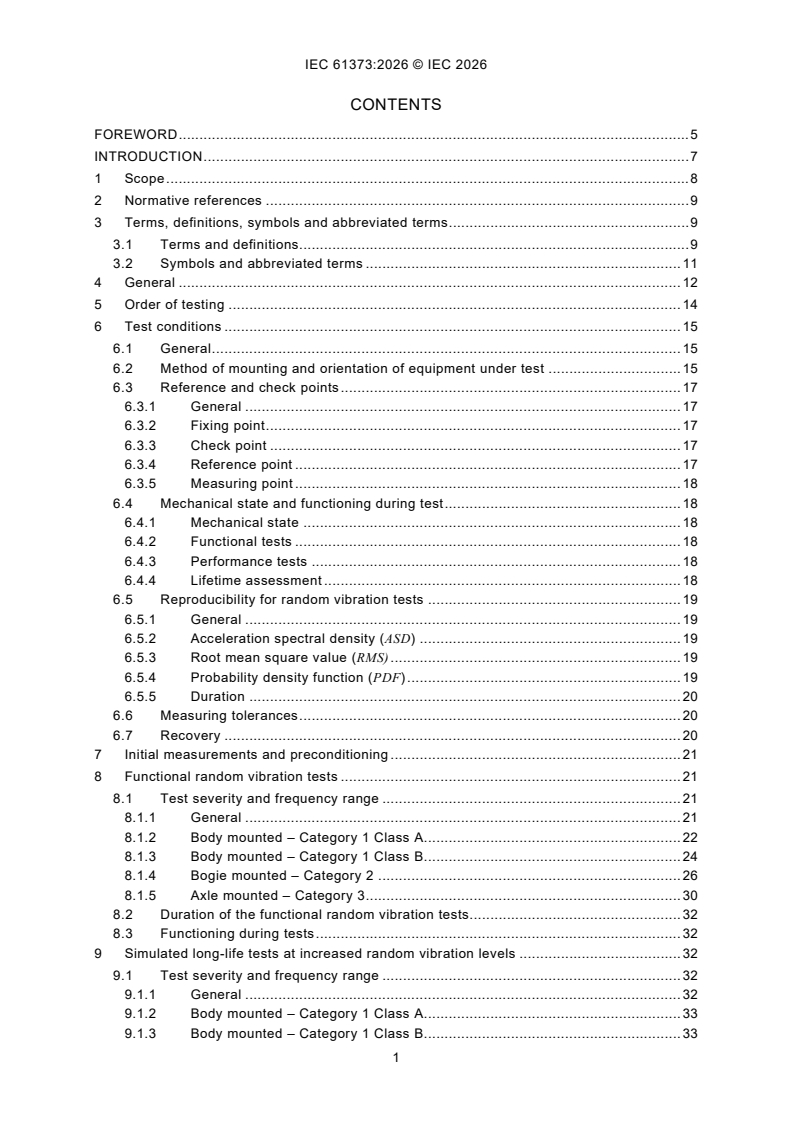
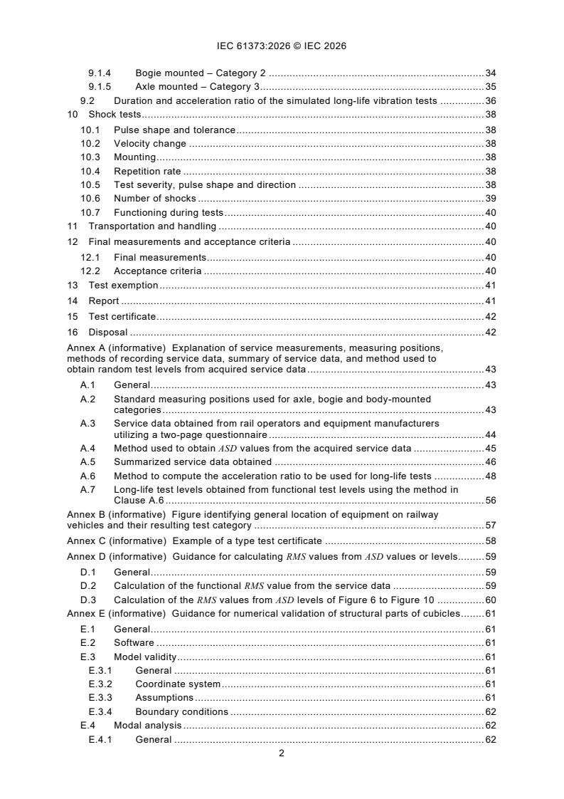
The standard is organized into clauses for scope, normative references, terms, general requirements, test order, test conditions, initial and final measurements, functional random vibration tests, simulated long-life tests, shock tests, reporting, certification and disposal. Its annexes add the service-data method, vehicle-location categories, a type-test certificate example, RMS calculation guidance, numerical validation guidance for cubicles, and default values for urban vehicles operating on pneumatic tyres.
| Annex | What it covers |
|---|---|
| Annex A | Service measurements, measuring positions, recording methods, summary of service data, and derivation of random test levels from service data |
| Annex B | Equipment location on railway vehicles and the resulting test category |
| Annex C | Example of a type test certificate |
| Annex D | Guidance for calculating RMS values from ASD values or levels |
| Annex E | Guidance for numerical validation of structural parts of cubicles |
| Annex F | Functional random vibration loads for urban vehicles operating on pneumatic tyres |
What are the key requirements of IEC 61373:2026?
IEC 61373:2026 requires three test families for compliance: a functional random vibration test, a simulated long-life random vibration test and a shock test. Clause 12 then sets the acceptance criteria, so the document is not just about applying loads - it also defines what evidence is needed to show the equipment still meets its intended function and mechanical condition.
Test category and mounting location
Clause 4 classifies equipment by mounting location only: Category 1 for body-mounted equipment, Category 2 for bogie-mounted equipment and Category 3 for axle-mounted equipment. Category 1 is split into Class A and Class B, with Class B used for equipment in an equipment case on the car body and in cases where the location is unclear or where there is a direct mechanical link between the car body and traction motors.
This matters because the test levels depend on location, not on product name alone. A supplier needs to choose the right category before setting up the test, otherwise the applied spectrum and shock severity may not match the intended installation.
Test order, mounting and pre-test checks
Clause 5 allows the vertical, transverse and longitudinal axes to be tested in any order, and the test sequence has to be recorded in the report. Clause 6 requires the equipment to be mounted in a way that represents vehicle installation, with bolts tightened to nominal design torque, and preferably in its normal working orientation.
Clause 7 requires a performance test before vibration and shock testing, and Clause 12 repeats the performance test after testing. For structural parts, the document uses transfer functions and requires coherence of at least 0.9 where possible, or a fallback of at least 120 spectral averages with 0 % overlap.
In practice, this means the test house must document the mounting arrangement, measuring points and baseline condition before stressing the equipment. If the equipment changes during test, the before-and-after comparison is part of the evidence.
Functional random vibration testing
Clause 8 gives the functional random vibration spectra and frequency ranges for each category and axis. The standard expects the equipment to function during this test, and Clause 4 says the functional random test levels are the minimum levels used to show that the equipment can operate under service-like vibration.
This matters because the test is not a full performance qualification under all conditions. The equipment should keep working within its defined functional limits while the spectrum representative of its mounting location is applied.
Simulated long-life vibration testing
Clause 9 raises the random vibration level to assess long-life mechanical integrity. The duration per axis is set between 5 h and 100 h, and the acceleration ratio is taken from Table 13 by default, with a specific ratio allowed when fatigue strength curves are known.
Clause 9 also allows the long-life load to be adjusted if resilient mounts are removed, provided the transfer function has been established, and it allows the use of measuring points to monitor non-linear behavior. For simultaneous multi-axis testing, the same acceleration ratio is used for all three axes.
In practice, this test is about durability rather than functionality. The equipment does not need to operate during the long-life test unless internal loads or motion make that necessary, but the mechanical condition must remain acceptable.
Shock testing
Clause 10 requires a sequence of single half-sine pulses, with pulse shape, duration, peak acceleration and direction taken from Table 14 and IEC 60068-2-27. Eighteen shocks are applied - three positive and three negative in each of the three orthogonal axes - and the equipment does not need to operate during the shock test.
This matters for equipment that may see rare events such as impacts in service. The test house must also pay attention to velocity change, repetition rate and the mounting arrangement, and the report must state any alternative waveform used for heavy equipment or bench limitations.
Acceptance, exemption and reporting
Clause 12 says the equipment is suitable for test certification when performance and function remain within limits, there is no visual deformation, mechanical integrity has not changed and marked bolts have not visibly misaligned after functional random vibration testing. Clause 13 allows test exemption by using subassemblies, FEA or a combination of testing and FEA for structural parts of a cubicle, with Annex E giving guidance.
Clauses 14 and 15 require a detailed report and a test certificate. The report has to cover the mounting method, order of testing, measurement locations, pre-test and post-test results, tolerance bands, and any specific acceleration ratio used. The certificate identifies the equipment, manufacturer, serial number, report number and whether certification is limited to a specific case.
What terms does IEC 61373:2026 define?
- Random vibration - vibration whose instantaneous value cannot be precisely predicted at a given time.
- Gaussian distribution - a probability distribution used here to describe the statistical shape of random vibration values.
- Acceleration spectral density (ASD) - the mean-square acceleration per unit bandwidth, used to define the vibration spectrum applied in the test.
- Acceleration ratio - the coefficient applied to the functional ASD value to obtain the simulated long-life ASD value.
- Cubicle - a self-contained item of equipment that includes structure, mechanical parts and mounted components.
- Weakest point - the structural area with the lowest margin of safety under fatigue loading.
- Probability density function (PDF) - the distribution used to describe the likelihood of instantaneous vibration values in the random signal.
Who uses IEC 61373:2026?
IEC 61373:2026 is used by railway equipment manufacturers, test laboratories, certification bodies, design engineers and quality managers. It is relevant for suppliers of cubicles, subassemblies, equipment and components mounted on the car body, bogie or axle.
Teams use it to define vibration and shock test specifications, set up test benches, choose measuring points, verify structural integrity, and document test results for type testing or certification. It is also useful when a customer wants evidence for a specific installation case or for equipment used on urban vehicles operating on pneumatic tyres.
What changed in IEC 61373:2026 from the previous edition?
IEC 61373:2026 is the third edition and cancels and replaces the second edition published in 2010. The foreword states these significant technical changes:
- specific ASD spectra from onboard measurements are considered, with certification limited to the specific case
- traction motors and any substructure without an electrical, electronic or pneumatic device are excluded from the scope
- the order of testing is clarified, including the possibility of simultaneous multi-axis testing
- guidance is added for removing resilient mounts during long-life testing
- the fixture device used to attach the equipment to the test bench is qualified
- a measuring point may be used to assess mechanical integrity
- the method for calculating the acceleration ratio is changed
- long-life test duration can be set from 5 h to 100 h per axis, with default ratios given in a table
- the concept of structural integrity is clarified
- test exemption cases, subassembly tests and FEA are described in new Annex E
- the lowest ASD frequency is fixed at 5 Hz for Categories 1 and 2 and at 10 Hz for Category 3
- ASD spectra for functional random vibration tests are updated
- Annex F is added for urban vehicles operating on pneumatic tyres
Which standards are used with IEC 61373:2026?
IEC 61373:2026 cites these normative references:
- IEC 60068-2-27 - gives the shock test method used for pulse shape, velocity change and shock guidance
- IEC 60068-2-47 - gives mounting guidance for specimens in vibration, impact and similar dynamic tests
- IEC 60068-2-64:2008 and IEC 60068-2-64:2008/AMD1:2019 - provide the broadband random vibration framework and tolerances used with this document
- ISO 3534-1 - provides statistical vocabulary and symbols used for probability terms
For structural assessment, Annex E refers to the EN 17149 series, including EN 17149-3 for fatigue strength assessment, and the foreword notes EN 12663 and EN 13749 as examples of structural requirement standards.
What does the IEC 61373:2026 document contain?
IEC 61373:2026 contains the test categories, ASD spectra, RMS values, pulse shapes, frequency ranges, durations and reporting items needed to run railway shock and vibration qualification tests. It also includes formulas and procedures for deriving test levels from service measurements, adjusting long-life test severity, and calculating transfer functions and RMS values.
Annex A contains service-data questionnaires, measuring positions and worked methods for turning field data into test levels. Annex D provides RMS calculation guidance from ASD data, while Annex E gives numerical validation guidance with modal analysis, shock and random vibration evaluation for cubicles. Annex F gives default functional random vibration data for urban vehicles operating on pneumatic tyres.
Relations
- Effective Date
- 05-Sep-2023
- Effective Date
- 05-Sep-2023
Get Certified
Connect with accredited certification bodies for this standard

IRIS Certification (UNIFE)
International Railway Industry Standard certification.

TÜV SÜD Rail GmbH
TÜV SÜD railway certification services.

Bureau Veritas Railway Certification
Railway and transportation certification.
Sponsored listings
Frequently Asked Questions
IEC 61373:2026 is a standard published by the International Electrotechnical Commission (IEC). Its full title is "Railway applications - Rolling stock equipment - Shock and vibration tests". This standard covers: IEC 61373:2026 specifies the requirements for testing items of equipment intended for use on railway vehicles which are subsequently subjected to vibrations and shock owing to the nature of railway operational environment. To gain assurance that the quality of the equipment is acceptable, it is exposed to tests of reasonable duration that simulate the service conditions seen throughout its expected life. Simulated long-life testing can be achieved in a number of ways each having their associated advantages and disadvantages, the following being the most common: a) amplification: where the amplitudes are increased and the time base decreased; b) time compression: where the amplitude history is retained and the time base is decreased (increase of the frequency); c) decimation: where time slices of the historical data are removed when the amplitudes are below a specified threshold value. The amplification method as stated in item a) above, is used in this document and together with the publications referred to in Clause 2; it defines the default test procedure to be followed when vibration testing items for use on railway vehicles. Whilst this document is primarily concerned with railway vehicles on fixed rail systems, its wider use is not precluded. For systems operating on pneumatic tyres, or other transportation systems such as trolleybuses, where the level of shock and vibration clearly differ from those obtained on fixed rail systems, specific test levels can be considered. In that case, the frequency spectra and the shock duration and amplitude are computed in compliance with the guidelines in Annex A. Annex F provides the functional random vibration load that can be considered by the user for urban vehicles operating on pneumatic tyres. This document applies to single axis testing. However, multi-axis testing is possible. The anchoring bolts at the fixing point(s) of the equipment are not evaluated in this document. This document is intended to evaluate equipment which is attached to the main structure of the vehicle (and components mounted thereon). It is not intended to test equipment which forms part of the main structure. Main structure in the sense of this document means car body, bogie and axle. The following items are out of scope of this document: – the traction motors for railway vehicles; – any mechanical substructure not equipped with electrical, electronic or pneumatic component. Additional or special vibration tests for some specific equipment are not specified in this document, for example: a) equipment mounted on, or linked to, items which are known to produce defined frequency excitation; b) equipment such as pantographs, shoegear, or suspension components which are known to be exposed to specific shock and vibration excitation; c) equipment intended for use in special operational environments as specified by the customer; d) transportation and handling tests. This third edition cancels and replaces the second edition published in 2010. This edition constitutes a technical revision. This edition includes the following significant technical changes with respect to the previous edition: a) consideration of specific ASD spectra from onboard measurements and certification limited to the specific case; b) exclusion from the scope of applicability of traction motors and any substructure not equipped with electrical, electronic or pneumatic device; c) clarification for order of testing and typical test sequence, taking into account the possibility of simultaneous multi-axis testing; d) recommendation and guidance for removing resilient mounts of the equipment (if located between the equipment and the main structure) during the long-life test; e) qualification of the fixture device used to attach the equipment to the test bench; f) guidance for using a measuring point as a possibility to assess mechanical integrity; g) change of the method to calculate the acceleration ratio which shall b
IEC 61373:2026 specifies the requirements for testing items of equipment intended for use on railway vehicles which are subsequently subjected to vibrations and shock owing to the nature of railway operational environment. To gain assurance that the quality of the equipment is acceptable, it is exposed to tests of reasonable duration that simulate the service conditions seen throughout its expected life. Simulated long-life testing can be achieved in a number of ways each having their associated advantages and disadvantages, the following being the most common: a) amplification: where the amplitudes are increased and the time base decreased; b) time compression: where the amplitude history is retained and the time base is decreased (increase of the frequency); c) decimation: where time slices of the historical data are removed when the amplitudes are below a specified threshold value. The amplification method as stated in item a) above, is used in this document and together with the publications referred to in Clause 2; it defines the default test procedure to be followed when vibration testing items for use on railway vehicles. Whilst this document is primarily concerned with railway vehicles on fixed rail systems, its wider use is not precluded. For systems operating on pneumatic tyres, or other transportation systems such as trolleybuses, where the level of shock and vibration clearly differ from those obtained on fixed rail systems, specific test levels can be considered. In that case, the frequency spectra and the shock duration and amplitude are computed in compliance with the guidelines in Annex A. Annex F provides the functional random vibration load that can be considered by the user for urban vehicles operating on pneumatic tyres. This document applies to single axis testing. However, multi-axis testing is possible. The anchoring bolts at the fixing point(s) of the equipment are not evaluated in this document. This document is intended to evaluate equipment which is attached to the main structure of the vehicle (and components mounted thereon). It is not intended to test equipment which forms part of the main structure. Main structure in the sense of this document means car body, bogie and axle. The following items are out of scope of this document: – the traction motors for railway vehicles; – any mechanical substructure not equipped with electrical, electronic or pneumatic component. Additional or special vibration tests for some specific equipment are not specified in this document, for example: a) equipment mounted on, or linked to, items which are known to produce defined frequency excitation; b) equipment such as pantographs, shoegear, or suspension components which are known to be exposed to specific shock and vibration excitation; c) equipment intended for use in special operational environments as specified by the customer; d) transportation and handling tests. This third edition cancels and replaces the second edition published in 2010. This edition constitutes a technical revision. This edition includes the following significant technical changes with respect to the previous edition: a) consideration of specific ASD spectra from onboard measurements and certification limited to the specific case; b) exclusion from the scope of applicability of traction motors and any substructure not equipped with electrical, electronic or pneumatic device; c) clarification for order of testing and typical test sequence, taking into account the possibility of simultaneous multi-axis testing; d) recommendation and guidance for removing resilient mounts of the equipment (if located between the equipment and the main structure) during the long-life test; e) qualification of the fixture device used to attach the equipment to the test bench; f) guidance for using a measuring point as a possibility to assess mechanical integrity; g) change of the method to calculate the acceleration ratio which shall b
IEC 61373:2026 is classified under the following ICS (International Classification for Standards) categories: 45.060.01 - Railway rolling stock in general. The ICS classification helps identify the subject area and facilitates finding related standards.
IEC 61373:2026 has the following relationships with other standards: It is inter standard links to IEC 61373:2010, IEC 61373:2010/COR1:2011. Understanding these relationships helps ensure you are using the most current and applicable version of the standard.
IEC 61373:2026 is available in PDF format for immediate download after purchase. The document can be added to your cart and obtained through the secure checkout process. Digital delivery ensures instant access to the complete standard document.
Standards Content (Sample)
IEC 61373 ®
Edition 3.0 2026-07
INTERNATIONAL
STANDARD
Railway applications - Rolling stock equipment - Shock and vibration tests
ICS 45.060.01 ISBN 978-2-8327-1205-4
All rights reserved. Unless otherwise specified, no part of this publication may be reproduced or utilized in any form or
by any means, electronic or mechanical, including photocopying and microfilm, without permission in writing from either
IEC or IEC's member National Committee in the country of the requester. If you have any questions about IEC copyright
or have an enquiry about obtaining additional rights to this publication, please contact the address below or your local
IEC member National Committee for further information.
IEC Secretariat Tel.: +41 22 919 02 11
3, rue de Varembé info@iec.ch
CH-1211 Geneva 20 www.iec.ch
Switzerland
About the IEC
The International Electrotechnical Commission (IEC) is the leading global organization that prepares and publishes
International Standards for all electrical, electronic and related technologies.
About IEC publications
The technical content of IEC publications is kept under constant review by the IEC. Please make sure that you have the
latest edition, a corrigendum or an amendment might have been published.
IEC publications search - IEC Products & Services Portal - products.iec.ch
webstore.iec.ch/advsearchform Discover our powerful search engine and read freely all the
The advanced search enables to find IEC publications by a publications previews, graphical symbols and the glossary.
variety of criteria (reference number, text, technical With a subscription you will always have access to up to date
committee, …). It also gives information on projects, content tailored to your needs.
replaced and withdrawn publications.
Electropedia - www.electropedia.org
The world's leading online dictionary on electrotechnology,
IEC Just Published - webstore.iec.ch/justpublished
Stay up to date on all new IEC publications. Just Published containing more than 22 500 terminological entries in English
details all new publications released. Available online and and French, with equivalent terms in 25 additional languages.
once a month by email. Also known as the International Electrotechnical Vocabulary
(IEV) online.
IEC Customer Service Centre - webstore.iec.ch/csc
If you wish to give us your feedback on this publication or
need further assistance, please contact the Customer
Service Centre: sales@iec.ch.
CONTENTS
FOREWORD . 5
INTRODUCTION . 7
1 Scope . 8
2 Normative references . 9
3 Terms, definitions, symbols and abbreviated terms . 9
3.1 Terms and definitions. 9
3.2 Symbols and abbreviated terms . 11
4 General . 12
5 Order of testing . 14
6 Test conditions . 15
6.1 General . 15
6.2 Method of mounting and orientation of equipment under test . 15
6.3 Reference and check points . 17
6.3.1 General . 17
6.3.2 Fixing point . 17
6.3.3 Check point . 17
6.3.4 Reference point . 17
6.3.5 Measuring point . 18
6.4 Mechanical state and functioning during test . 18
6.4.1 Mechanical state . 18
6.4.2 Functional tests . 18
6.4.3 Performance tests . 18
6.4.4 Lifetime assessment . 18
6.5 Reproducibility for random vibration tests . 19
6.5.1 General . 19
6.5.2 Acceleration spectral density (ASD) . 19
6.5.3 Root mean square value (RMS) . 19
6.5.4 Probability density function (PDF) . 19
6.5.5 Duration . 20
6.6 Measuring tolerances . 20
6.7 Recovery . 20
7 Initial measurements and preconditioning . 21
8 Functional random vibration tests . 21
8.1 Test severity and frequency range . 21
8.1.1 General . 21
8.1.2 Body mounted – Category 1 Class A. 22
8.1.3 Body mounted – Category 1 Class B. 24
8.1.4 Bogie mounted – Category 2 . 26
8.1.5 Axle mounted – Category 3 . 30
8.2 Duration of the functional random vibration tests. 32
8.3 Functioning during tests . 32
9 Simulated long-life tests at increased random vibration levels . 32
9.1 Test severity and frequency range . 32
9.1.1 General . 32
9.1.2 Body mounted – Category 1 Class A. 33
9.1.3 Body mounted – Category 1 Class B. 33
9.1.4 Bogie mounted – Category 2 . 34
9.1.5 Axle mounted – Category 3 . 35
9.2 Duration and acceleration ratio of the simulated long-life vibration tests . 36
10 Shock tests . 38
10.1 Pulse shape and tolerance . 38
10.2 Velocity change . 38
10.3 Mounting . 38
10.4 Repetition rate . 38
10.5 Test severity, pulse shape and direction . 38
10.6 Number of shocks . 39
10.7 Functioning during tests . 40
11 Transportation and handling . 40
12 Final measurements and acceptance criteria . 40
12.1 Final measurements. 40
12.2 Acceptance criteria . 40
13 Test exemption . 41
14 Report . 41
15 Test certificate . 42
16 Disposal . 42
Annex A (informative) Explanation of service measurements, measuring positions,
methods of recording service data, summary of service data, and method used to
obtain random test levels from acquired service data . 43
A.1 General . 43
A.2 Standard measuring positions used for axle, bogie and body-mounted
categories . 43
A.3 Service data obtained from rail operators and equipment manufacturers
utilizing a two-page questionnaire . 44
A.4 Method used to obtain ASD values from the acquired service data . 45
A.5 Summarized service data obtained . 46
A.6 Method to compute the acceleration ratio to be used for long-life tests . 48
A.7 Long-life test levels obtained from functional test levels using the method in
Clause A.6 . 56
Annex B (informative) Figure identifying general location of equipment on railway
vehicles and their resulting test category . 57
Annex C (informative) Example of a type test certificate . 58
Annex D (informative) Guidance for calculating RMS values from ASD values or levels. 59
D.1 General . 59
D.2 Calculation of the functional RMS value from the service data . 59
D.3 Calculation of the RMS values from ASD levels of Figure 6 to Figure 10 . 60
Annex E (informative) Guidance for numerical validation of structural parts of cubicles . 61
E.1 General . 61
E.2 Software . 61
E.3 Model validity . 61
E.3.1 General . 61
E.3.2 Coordinate system . 61
E.3.3 Assumptions . 61
E.3.4 Boundary conditions . 62
E.4 Modal analysis . 62
E.4.1 General . 62
E.4.2 Post processing . 62
E.4.3 Criteria . 62
E.5 Shocks . 62
E.5.1 General . 62
E.5.2 Loading . 62
E.5.3 Post processing . 63
E.5.4 Acceptance criteria . 63
E.6 Random vibration . 63
E.6.1 General . 63
E.6.2 Post processing . 64
E.6.3 Acceptance criteria . 67
Annex F (informative) Urban vehicles operating on pneumatic tyres. 69
F.1 General . 69
F.2 Specific layout of urban vehicles operating on pneumatic tyres . 69
F.3 Functional random vibration ASD . 70
Bibliography . 73
Figure 1 – Gaussian distribution . 10
Figure 2 – Test sequence . 14
Figure 3 – Management of resilient mounts during testing . 15
Figure 4 – Example of transfer function magnitude . 16
Figure 5 – Cumulative PDF tolerance bands . 20
Figure 6 – Category 1 – Class A – Body-mounted – ASD spectra . 23
Figure 7 – Category 1 – Class B – Body-mounted – ASD spectra . 26
Figure 8 – Category 2 – Bogie mounted – ASD spectra . 28
Figure 9 – Category 2 – Bogie mounted – Validity plan for default ASD spectra . 29
Figure 10 – Category 3 – Axle mounted – ASD spectra . 31
Figure 11 – Pulse shape and limits of tolerance for half-sine pulse . 39
Figure A.1 – Standard measuring positions used for axle, bogie (frame) and body . 43
Figure A.2 – Typical fatigue strength curve . 48
Figure A.3 – Acceleration ratio as function as number of cycles during long life test N . 50
T
Figure A.4 – Default acceleration ratio as function as long-life test duration d for
LLT
categories 1 and 2 . 51
Figure A.5 – Default acceleration ratio as function as long-life test duration d for
LLT
category 3 . 52
Figure B.1 – General location of equipment on vehicles . 57
Figure D.1 – ASD spectrum . 60
Figure E.1 – Stress value on element, frequency response analysis . 64
Figure E.2 – Power spectral density, acceleration and stress σ (f) . 65
PSD
Figure F.1 – General location of equipment on vehicles operating on pneumatic tyres . 70
Table 1 – Test severity and frequency range for functional random vibration tests of
category 1 Class A . 24
Table 2 – Test severity and frequency range for functional random vibration tests of
category 1 Class B . 26
Table 3 – Test severity and frequency range for functional random vibration tests of
category 2 . 29
Table 4 – Test severity and frequency range for functional random vibration tests of
category 3 . 32
Table 5 – Test severity and frequency range for 5 h simulated long-life random
vibration tests of category 1 Class A . 33
Table 6 – Test severity and frequency range for 100 h simulated long-life random
vibration tests of category 1 Class A . 33
Table 7 – Test severity and frequency range for 5 h simulated long-life random
vibration tests of category 1 Class B . 34
Table 8 – Test severity and frequency range for 100 h simulated long-life random
vibration tests of category 1 Class B . 34
Table 9 – Test severity and frequency range for 5 h simulated long-life random
vibration tests of category 2 . 34
Table 10 – Test severity and frequency range for 100 h simulated long-life random
vibration tests of category 2 . 35
Table 11 – Test severity and frequency range for 5 h simulated long-life random
vibration tests of category 3 . 35
Table 12 – Test severity and frequency range for 100 h simulated long-life random
vibration tests of category 3 . 36
Table 13 – Acceleration ratio and long-life test duration table (default values) . 37
Table 14 – Test severity, pulse shape and direction . 39
Table A.1 – Environment data acquisition summary of the test parameters . 44
Table A.2 – Summary of the additional RMS acceleration levels obtained from the
questionnaire . 46
Table A.3 – Summary of collected data (category 1A) . 47
Table A.4 – Summary of collected data (category 1B) . 47
Table A.5 – Fatigue curves parameters considered for default acceleration ratio
computation . 49
Table A.6 – Acceleration ratio and long-life test duration table (default values) . 52
Table A.7 – Parameters for specific acceleration ratio computation (Example 1) . 54
Table A.8 – Parameters for specific acceleration ratio computation (Example 2) . 55
Table E.1 – Description of stress spectrum . 66
Table F.1 – Test severity and frequency range for functional random vibration tests of
category 1 Class A, urban vehicle operating on pneumatic tyres . 71
Table F.2 – Test severity and frequency range for functional random vibration tests of
category 1 Class B, urban vehicle operating on pneumatic tyres . 71
Table F.3 – Test severity and frequency range for functional random vibration tests of
category 2, urban vehicle operating on pneumatic tyres . 72
INTERNATIONAL ELECTROTECHNICAL COMMISSION
____________
Railway applications - Rolling stock equipment -
Shock and vibration tests
FOREWORD
1) The International Electrotechnical Commission (IEC) is a worldwide organization for standardization comprising
all national electrotechnical committees (IEC National Committees). The object of IEC is to promote international
co-operation on all questions concerning standardization in the electrical and electronic fields. To this end and
in addition to other activities, IEC publishes International Standards, Technical Specifications, Technical Reports,
Publicly Available Specifications (PAS) and Guides (hereafter referred to as "IEC Publication(s)"). Their
preparation is entrusted to technical committees; any IEC National Committee interested in the subject dealt with
may participate in this preparatory work. International, governmental and non-governmental organizations liaising
with the IEC also participate in this preparation. IEC collaborates closely with the International Organization for
Standardization (ISO) in accordance with conditions determined by agreement between the two organizations.
2) The formal decisions or agreements of IEC on technical matters express, as nearly as possible, an international
consensus of opinion on the relevant subjects since each technical committee has representation from all
interested IEC National Committees.
3) IEC Publications have the form of recommendations for international use and are accepted by IEC National
Committees in that sense. While all reasonable efforts are made to ensure that the technical content of IEC
Publications is accurate, IEC cannot be held responsible for the way in which they are used or for any
misinterpretation by any end user.
4) In order to promote international uniformity, IEC National Committees undertake to apply IEC Publications
transparently to the maximum extent possible in their national and regional publications. Any divergence between
any IEC Publication and the corresponding national or regional publication shall be clearly indicated in the latter.
5) IEC itself does not provide any attestation of conformity. Independent certification bodies provide conformity
assessment services and, in some areas, access to IEC marks of conformity. IEC is not responsible for any
services carried out by independent certification bodies.
6) All users should ensure that they have the latest edition of this publication.
7) No liability shall attach to IEC or its directors, employees, servants or agents including individual experts and
members of its technical committees and IEC National Committees for any personal injury, property damage or
other damage of any nature whatsoever, whether direct or indirect, or for costs (including legal fees) and
expenses arising out of the publication, use of, or reliance upon, this IEC Publication or any other IEC
Publications.
8) Attention is drawn to the Normative references cited in this publication. Use of the referenced publications is
indispensable for the correct application of this publication.
9) IEC draws attention to the possibility that the implementation of this document may involve the use of (a)
patent(s). IEC takes no position concerning the evidence, validity or applicability of any claimed patent rights in
respect thereof. As of the date of publication of this document, IEC had not received notice of (a) patent(s), which
may be required to implement this document. However, implementers are cautioned that this may not represent
the latest information, which may be obtained from the patent database available at https://patents.iec.ch. IEC
shall not be held responsible for identifying any or all such patent rights.
IEC 61373 has been prepared by IEC technical committee 9: Electrical equipment and systems
for railways. It is an International Standard.
This third edition cancels and replaces the second edition published in 2010. This edition
constitutes a technical revision.
This edition includes the following significant technical changes with respect to the previous
edition:
a) consideration of specific ASD spectra from onboard measurements and certification limited
to the specific case;
b) exclusion from the scope of applicability of traction motors and any substructure not
equipped with electrical, electronic or pneumatic device;
c) clarification for order of testing and typical test sequence, taking into account the possibility
of simultaneous multi-axis testing;
d) recommendation and guidance for removing resilient mounts of the equipment (if located
between the equipment and the main structure) during the long-life test;
e) qualification of the fixture device used to attach the equipment to the test bench;
f) guidance for using a measuring point as a possibility to assess mechanical integrity;
g) change of the method to calculate the acceleration ratio which shall be applied to the
functional ASD value to obtain the simulated long-life ASD value;
h) duration of long-life test can be set from 5 h to 100 h per axis, with corresponding
acceleration ratio (default value) indicated in a table;
i) clarification of the concept of structural integrity;
j) description of test exemption cases, subassembly tests, and finite element analysis for
structural parts of equipment (new Annex E);
k) the lowest frequency f of ASD spectra of Category 1 and Category 2 is fixed at 5 Hz as a
default value, and the lowest frequency f of ASD spectra of Category 3 is fixed at 10 Hz as
a default value;
l) update of ASD spectra for functional random vibration test: Table 1, Table 2, Table 3,
Table 4, Table A.2 and Figure 6, Figure 7, Figure 8, Figure 10. This update was
recommended in the Rail Safety and Standard Board research program document:
“Vibration environment for rail vehicle mounted Equipment”;
m) new annex F dedicated on urban vehicle operating on pneumatic tyres.
The text of this International Standard is based on the following documents:
Draft Report on voting
9/3266/FDIS 9/3321/RVD
Full information on the voting for its approval can be found in the report on voting indicated in
the above table.
The language used for the development of this International Standard is English.
This document was drafted in accordance with ISO/IEC Directives, Part 2, and developed in
accordance with ISO/IEC Directives, Part 1 and ISO/IEC Directives, IEC Supplement, available
at www.iec.ch/members_experts/refdocs. The main document types developed by IEC are
described in greater detail at www.iec.ch/publications.
The committee has decided that the contents of this document will remain unchanged until the
stability date indicated on the IEC website under webstore.iec.ch in the data related to the
specific document. At this date, the document will be
– reconfirmed,
– withdrawn, or
– revised.
INTRODUCTION
This document covers the requirements for random vibration and shock testing items of
pneumatic, electrical and electronic equipment or components (hereinafter only referred to as
equipment) to be fitted on to railway vehicles. Random vibration and shock is the only method
to be used for equipment or component approval.
The tests contained within this document are specifically aimed at demonstrating the ability of
the equipment under test to withstand the type of environmental vibration conditions normally
expected for railway vehicles. In order to achieve the best representation possible, the values
quoted in this document have been derived from actual service measurements submitted by
various contributing bodies from around the world.
This document is not intended to cover self-induced vibrations as these will be specific to
particular applications.
Engineering judgement and experience are recommended in the execution and interpretation
of this document.
This document is suitable for design and validation purposes; however, it does not exclude the
use of other development tools (such as sine sweep), which can be used to ensure a
predetermined degree of mechanical and operational confidence. The test levels to be applied
to the equipment under test are dictated only by its location on the train (i.e. axle, bogie or
body-mounted).
It should be noted that these tests can be performed on prototypes in order to gain design
information about the product performance under random vibration. However, for test
certification purposes, the tests are carried out on equipment taken from normal production.
The procedures and requirements defined in this document do not substitute or overrule any
structural assessment required from other structural requirement standards. This document is
not intended to be used as a proof of fatigue strength.
NOTE European Standards EN 12663 and EN 13749 are examples of such structural requirement standards.
1 Scope
This document specifies the requirements for testing items of equipment intended for use on
railway vehicles which are subsequently subjected to vibrations and shock owing to the nature
of railway operational environment. To gain assurance that the quality of the equipment is
acceptable, it is exposed to tests of reasonable duration that simulate the service conditions
seen throughout its expected life.
Simulated long-life testing can be achieved in a number of ways each having their associated
advantages and disadvantages, the following being the most common:
a) amplification: where the amplitudes are increased and the time base decreased;
b) time compression: where the amplitude history is retained and the time base is decreased
(increase of the frequency);
c) decimation: where time slices of the historical data are removed when the amplitudes are
below a specified threshold value.
The amplification method as stated in item a) above, is used in this document and together with
the publications referred to in Clause 2; it defines the default test procedure to be followed
when vibration testing items for use on railway vehicles.
Whilst this document is primarily concerned with railway vehicles on fixed rail systems, its wider
use is not precluded. For systems operating on pneumatic tyres, or other transportation systems
such as trolleybuses, where the level of shock and vibration clearly differ from those obtained
on fixed rail systems, specific test levels can be considered. In that case, the frequency spectra
and the shock duration and amplitude are computed in compliance with the guidelines in
Annex A.
Annex F provides the functional random vibration load that can be considered by the user for
urban vehicles operating on pneumatic tyres.
This document applies to single axis testing. However, multi-axis testing is possible.
The anchoring bolts at the fixing point(s) of the equipment are not evaluated in this document.
This document is intended to evaluate equipment which is attached to the main structure of the
vehicle (and components mounted thereon). It is not intended to test equipment which forms
part of the main structure. Main structure in the sense of this document means car body, bogie
and axle.
The following items are out of scope of this document:
– the traction motors for railway vehicles;
– any mechanical substructure not equipped with electrical, electronic or pneumatic
component.
Additional or special vibration tests for some specific equipment are not specified in this
document, for example:
a) equipment mounted on, or linked to, items which are known to produce defined frequency
excitation;
b) equipment such as pantographs, shoegear, or suspension components which are known to
be exposed to specific shock and vibration excitation;
c) equipment intended for use in special operational environments as specified by the
customer;
d) transportation and handling tests.
2 Normative references
The following documents are referred to in the text in such a way that some or all of their content
constitutes requirements of this document. For dated references, only the edition cited applies.
For undated references, the latest edition of the referenced document (including any
amendments) applies.
IEC 60068-2-27, Environmental testing - Part 2-27: Tests - Test Ea and guidance: Shock
IEC 60068-2-47, Environmental testing - Part 2-47: Test - Mounting of specimens for vibration,
impact and similar dynamic tests
IEC 60068-2-64:2008, Environmental testing - Part 2-64: Tests - Test Fh: Vibration, broadband
random and guidance
IEC 60068-2-64:2008/AMD1:2019
ISO 3534-1, Statistics - Vocabulary and symbols - Part 1: General statistical terms and terms
used in probability
3 Terms, definitions, symbols and abbreviated terms
3.1 Terms and definitions
For the purposes of this document, the terms and definitions given in IEC 60068-2-64,
ISO 3534-1 and the following apply.
ISO and IEC maintain terminology databases for use in standardization at the following
addresses:
– IEC Electropedia: available at https://www.electropedia.org/
– ISO Online browsing platform: available at https://www.iso.org/obp
3.1.1
random vibration
vibration the instantaneous value of which cannot be precisely predicted for any given instant
of time
3.1.2
Gaussian distribution
continuous distribution with probability density function equal to:
–(xx – )²
P ()x ×
2 ×σ²
x e
σ 2 × π
where
σ is the standard deviation;
x is the instantaneous value;
x is the mean value of x.
Note 1 to entry: See Figure 1.
=
Figure 1 – Gaussian distribution
Note 2 to entry: According to Figure 1, the probability that the instantaneous acceleration value is between ±a is
equal to the zone under the probability density curve P (x). This means that the instantaneous acceleration value
x
between:
– 0 and 1σ represents 68,26 % of the time,
– 1σ and 2σ represents 27,18 % of the time,
– 2σ and 3σ represents 4,30 % of the time.
3.1.3
acceleration spectral density
ASD
mean-square value of that part of an acceleration signal passed by a narrow-band filter of a
centre frequency, per unit bandwidth, in the limit as the bandwidth approaches zero and the
averaging time approaches infinity
3.1.4
component
pneumatic, electrical, or electronic part located inside a cubicle
3.1.5
cubicle
self-contained item of equipment, comprising structure, mechanical parts and mounted
components
Note 1 to entry: Examples include converter, inverter, battery box.
3.1.6
anchoring bolt
bolt that enables the assembly of the equipment on the test table or the fixture device
3.1.7
internal bolt
bolt used in the equipment itself
3.1.8
acceleration ratio
coefficient applied to the functional ASD value to obtain the simulated long-life ASD value
3.1.9
weakest point
structural area which provides the lowest margin of safety under fatigue loads
3.2 Symbols and abbreviated terms
ADC analog to digital converter
2 2
ASD acceleration spectral density ((m/s ) /Hz)
2 2
ASD ASD value of the measured data number "i" ((m/s ) /Hz)
i
DAT digital audio tape
d duration of the simulated long-life test (h)
LLT
DR digital recorder
d duration of the vehicle service life (h)
s
D total cumulated damage of each element
T
D cumulated damage of each element due to longitudinal acceleration
T
l
D cumulated damage of each element due to transverse acceleration
T
t
cumulated damage of each element due to vertical acceleration
D
T
v
D cumulated cumulative damage of each element due to longitudinal, transverse, and
T
ltv
vertical acceleration (multidirectional load case)
D cumulative admissible sum limit
M
d projected longitudinal distance between the fixing point of the equipment and the
X
validity plan (m)
E Young's Modulus of material (MPa)
E expected number of zero-crossings
E expected number of peaks
P
f frequency (Hz)
F force (N) or (daN), should be consistent with other values
f minimum frequency of ASD (Hz)
maximum frequency of ASD (Hz)
f
f frequency value of the measured data number "i" (Hz)
i
FDS fatigue damage spectrum
FTU ultimate stress (or tensile stress) of material (MPa)
FEA finite element analysis
FM frequency modulation
H transfer function
m mass of the equipment (kg)
m spectral moment rank n
n
n number of check point(s)
c
N the minimal number of cycles estimated during the service life
S
N the minimal number of cycles estimated during the long-life test
T
PCM pulse code modulation
PDF probability density function
R stress ratio (-)
RH relative humidity (%)
RMS root mean square value
RMS root mean square value of check point number “i”
i
R yield strength of material (MPa)
p
S safety factor (-)
WB wheelbase of the bogie (m)
∆f frequency resolution of the ASD (Hz)
∆σ fully reversed cut-off limit of material (MPa)
L
∆σ
RMS stress range of the block i on the element under functional ASD load (MPa)
RMS
i
γ irregularity factor
Ɛ material strain (%)
ε statistical error
S
σ stress at the centre of gravity of the element (MPa)
σ endurance limit of the material (MPa)
D
σ cut-off limit of the material (MPa)
L
ζ damping ratio (-)
4 General
This document is intended to highlight any weakness which can result in problems as a
consequence of operation under environments where vibration and shock are known to occur
in service on a railway vehicle. This is not intended to represent a full life test. However, the
test conditions are sufficient to provide some reasonable degree of confidence (depending on
hypothesis of fatigue strength parameters) that the equipment will survive the specified lifetime
under service conditions.
The test levels quoted in this document have been derived from environmental test data, as
referred to in Annex A. This information was submitted by organizations responsible for
collecting environmental vibration levels under service conditions.
The following tests are mandatory for compliance with this document:
Functional random test The functional random test levels are the minimum test levels
to be applied in order to demonstrate that the equipment under
test is capable of functioning when subjected to conditions
which are likely to occur in service, on railway vehicles.
The degree of functioning shall be defined prior to tests
beginning (see 6.4.2).
The functional random test is not intended to be a full
performance evaluation under simulated service conditions.
Functional random testing requirements are detailed in
Clause 8.
Simulated long-life test This test is aimed at establishing the mechanical integrity of
the equipment at increased service levels. It is not necessary
to demonstrate ability to function under these conditions.
Simulated long-life testing requirements are detailed in
Clause 9.
Shock test Shock test is aimed at simulating rare service events. It is not
necessary to demonstrate functionality during this test. Shock
test requirements are detailed in Clause 10.
The equipment shall comply with the acceptance criteria listed in Clause 12.
The test values quoted in this document have been divided into three categories dependent
only upon the equipment's location within the vehicle (see Figure B.1 of Annex B).
Category 1: Body mounted
Class A: Cubicles, subassemblies, equipment and components mounted directly on or under
the car body.
Class B: Anything mounted inside an equipment case which is in turn mounted directly on or
under the car body.
Class B is used:
– when it is not clear where the equipment is to be located;
– when there is a direct mechanical link between the car body and the traction motors.
Category 2: Bogie mounted
Cubicles, subassemblies, equipment and components which shall be mounted on the bogie of
a railway vehicle.
Category 3: Axle mounted
Subassemblies, equipment and components or assemblies which are to be mounted on the
wheelset assembly of a railway vehicle.
In the case of equipment mounted on vehicles with one level of suspension such as wagons
and trucks, axle mounted equipment are tested as category 3. For all other equipment, there is
no pre-defined associated category.
For reason of simplification, metric units are considered through this document.
5 Order of testing
Testing in the vertical, transverse and longitudinal axes can be performed in any order. A
possible sequence of testing is shown in Figure 2 for single axis test bench:
Figure 2 – Test sequence
The arrangement of shock test, functional random vibration test and simulated long-life vibration
test can vary from
...