

ISO/IEC 30188:2026
(Main)Digital twin - Reference architecture
- Abstract
ISO/IEC 30188:2026 specifies a general reference architecture for a digital twin system in terms of defining system fundamentals through the use of architecture views.
- Status
- Published
- Publication Date
- 21-Jul-2026
- Technical Committee
- ISO/IEC JTC 1/SC 41 - Internet of Things and Digital Twin
- Drafting Committee
- WG 6 - ISO/IEC JTC 1/SC 41/WG 6
- Current Stage
- PPUB - Publication issued
- Start Date
- 22-Jul-2026
- Completion Date
- 14-Aug-2026

ISO/IEC 30188:2026 is an International Standard from ISO and IEC that provides a general reference architecture for a digital twin system. It specifies the system fundamentals through architecture views, so architects, engineers, managers and owners can describe a digital twin in a consistent way across domains. The standard focuses on how to structure the architecture, not on one specific industry implementation.
What does ISO/IEC 30188:2026 specify?
ISO/IEC 30188:2026 specifies a general reference architecture for a digital twin system in terms of defining system fundamentals through the use of architecture views. Clause 5 frames the standard around architecture descriptions, while Clauses 6 to 8 develop the foundational, functional and implementation viewpoints, and Annex A adds a normative architecture pattern viewpoint.
The document is organized around the architecture description concepts from ISO/IEC/IEEE 42010. It uses viewpoints to frame stakeholder concerns and views to show the digital twin system from different angles.
The main structure is:
- Clause 1 - Scope
- Clause 2 - Normative references
- Clause 3 - Terms and definitions
- Clause 4 - Abbreviated terms
- Clause 5 - Specifying an architecture for digital twins
- Clause 6 - Foundational viewpoint
- Clause 7 - Functional viewpoint
- Clause 8 - Implementation viewpoint
- Annex A - Architecture pattern viewpoint
Annex A is normative and is used when an architect needs to extend or specialize the reference architecture with architecture patterns. That matters in practice because many digital twin projects need a common base model plus domain-specific constraints.
What are the key requirements of ISO/IEC 30188:2026?
ISO/IEC 30188:2026 sets out a reference architecture built from viewpoints and views, then defines what each view must cover. The most important technical content is the model of the digital twin itself, the lifecycle framing, the capability model, and the implementation concerns around interfaces, interoperability and model construction.
Clause 5 - How to specify a digital twin architecture
Clause 5 states that ISO/IEC/IEEE 42010 provides the structure for architecture descriptions, including viewpoints, stakeholder concerns and views. ISO/IEC 30188:2026 uses that approach and identifies four architecture views: foundational, functional, implementation and architecture pattern.
In practice, this means the standard is meant to help you write an architecture description, not just a concept note. If you are defining a digital twin program, Clause 5 gives you the organizing method for the rest of the standard.
Clause 6 - Foundational viewpoint
Clause 6 establishes the basic concepts of a digital twin. A digital twin (DTw) is a digital representation of a target entity with data connections that allow synchronization between the state of the target entity and the state of the digital representation. The target entity can be physical, digital, or both.
This matters because the standard does not limit digital twins to physical assets only. It supports cases where the target entity is a machine, a digital system, or a mixed physical-digital environment.
Clause 6 also defines the twinning model, the synchronization model, and the lifecycle model. The twinning model explains how one target entity can be twinned with one or more digital twins through data connection interfaces. The synchronization model explains how models and prediction functions use observation data to update the digital twin. The lifecycle model distinguishes full lifecycle twinning from partial lifecycle twinning.
For practice, this tells you whether your architecture needs continuous synchronization, periodic synchronization, or only a digital twin at a specific stage such as operation or retirement.
Clause 7 - Functional viewpoint
Clause 7 describes digital twin capabilities by lifecycle stage: design and development, deployment, operation and retirement. The capabilities are grouped into definition, execution, monitoring and measurement, analysis, control and optimization.
This is useful for scoping work packages and responsibilities. For example, the standard links design-stage capabilities to model design, simulation and AI support; operation-stage capabilities to interoperability support, real-time monitoring, troubleshooting and prediction; and retirement-stage capabilities to historical data, archiving and reuse.
Clause 7 also notes that security and privacy capabilities are not covered in the functional viewpoint and can be addressed through additional viewpoints using Annex A. In practice, that means teams should not assume the functional view is enough for governance, security or privacy planning.
Clause 8 - Implementation viewpoint
Clause 8 focuses on how to implement the digital twin in three areas: usage and business interfaces, interoperability, and model implementation. It distinguishes application services, supplier services and product services.
The interoperability part is especially practical. ISO/IEC 30188:2026 identifies inner interoperability between the digital twin and the target entity, outer interoperability between the target entity and its environment, and transversal interoperability between different digital twins. That helps you decide whether your implementation needs sensor-level links, external data exchange, or federated multi-twin integration.
Clause 8.2.4 also gives a model implementation path covering target entity modelling, state synchronization design, twin data construction, model construction, algorithm design and application design. In practice, this is the part that guides data collection, preprocessing, model building and the use of algorithm libraries.
Annex A - Architecture pattern viewpoint
Annex A provides the normative pattern viewpoint for extending the reference architecture. It is intended for architects who need to specialize the architecture for an application domain or integrate additional constructs from another domain standard.
This matters because the standard explicitly expects reuse and specialization. Annex A shows how to combine this architecture with patterns such as IoT, RAMI 4.0, maturity models and manufacturing frameworks.
What terms does ISO/IEC 30188:2026 define?
ISO/IEC 30188:2026 defines the key vocabulary needed to talk about digital twin architecture precisely.
- digital twin (DTw) - a digital representation of a target entity with data connections that keep the two states synchronized at an appropriate rate.
- target entity - the entity of interest for a digital twin; it may be physical, digital or both.
- observable entity - an entity in the environment of the target entity that can be observed and modelled in the digital twin.
- observation data - data produced by monitoring and measuring an observable entity.
- architecture view - a portion of an architecture description.
- architecture viewpoint - the conventions used to create and interpret an architecture view and frame concerns.
- capability - a measure of the capacity and ability of an entity to achieve its objectives.
- synchronization - the action of making the states of the digital twin and target entity synchronized.
The abbreviated terms include AI, DTw, IoT, IT and OT. These abbreviations matter because the standard uses them when discussing analytics, connected systems and industrial environments.
Who uses ISO/IEC 30188:2026?
ISO/IEC 30188:2026 is aimed at digital twin architects and engineers, project or programme managers, digital twin business managers and digital twin owners across application and technology domains. Clause 6 and Clause 8 also make it relevant to standards experts, systems engineers, business decision makers, market managers, product managers, third-party evaluators and users.
It is especially relevant in manufacturing, smart energy, smart cities, farming, buildings and healthcare. The introduction also links the standard to broader technical areas such as IoT, AI, security, privacy, cloud computing, simulation and automatic identification.
Which standards are used with ISO/IEC 30188:2026?
ISO/IEC 30188:2026 is built around ISO/IEC/IEEE 42010 for architecture descriptions. That standard supplies the concepts of viewpoints, views and stakeholder concerns used in Clause 5.
Other named standards contribute specific topics:
- ISO/IEC/IEEE 15288:2023 - system life cycle concepts used in the lifecycle definitions
- ISO/IEC/IEEE 24748-1 - lifecycle management guidance referenced in the lifecycle model
- ISO/IEC 21823-1 - interoperability framework used in Clause 8.2.3
- ISO/IEC 30141 - IoT reference architecture used in Annex A and in interoperability examples
- ISO/IEC 30173:2023 - digital twin concepts and terminology used in the definition of DTw
- ISO/IEC 30186 - maturity model referenced in Annex A
- ISO 23247 series - manufacturing digital twin framework used in Annex A examples
- IEC PAS 63088 and IEC SRD 63200 - reference-model examples for smart manufacturing and smart energy
- ISO/IEC TS 27570 and ISO/IEC TS 30149 - guidance points for privacy and trustworthiness in related viewpoints
These references show that ISO/IEC 30188:2026 is a cross-domain architecture standard that relies on established architecture, lifecycle, interoperability and domain-specific frameworks.
What does the ISO/IEC 30188:2026 document contain?
ISO/IEC 30188:2026 contains figures, tables, conceptual models and pattern examples rather than formulas or test methods. The figures illustrate the twinning model, synchronization model, physical, digital and combined target entity configurations, lifecycle twinning, interoperability types and model construction processes.
Tables 1 to 4 summarize capabilities by lifecycle stage in the functional viewpoint. Annex A adds Table A.2 as a pattern template and Tables A.3 to A.6 as examples for sensing and actuating, RAMI 4.0, maturity and manufacturing frameworks.
The annex also includes examples of additional views for IoT-related digital twins and a trustworthiness view. For practitioners, this means the document provides architecture language, stage-based capability mapping and pattern-based extension guidance for design, deployment, operation and specialization.
Get Certified
Connect with accredited certification bodies for this standard

BSI Group
BSI (British Standards Institution) is the business standards company that helps organizations make excellence a habit.

NYCE
Mexican standards and certification body.
Sponsored listings
Frequently Asked Questions
ISO/IEC 30188:2026 is a standard published by the International Electrotechnical Commission (IEC). Its full title is "Digital twin - Reference architecture". This standard covers: ISO/IEC 30188:2026 specifies a general reference architecture for a digital twin system in terms of defining system fundamentals through the use of architecture views.
ISO/IEC 30188:2026 specifies a general reference architecture for a digital twin system in terms of defining system fundamentals through the use of architecture views.
ISO/IEC 30188:2026 is classified under the following ICS (International Classification for Standards) categories: 35.020 - Information technology (IT) in general. The ICS classification helps identify the subject area and facilitates finding related standards.
ISO/IEC 30188:2026 is available in PDF format for immediate download after purchase. The document can be added to your cart and obtained through the secure checkout process. Digital delivery ensures instant access to the complete standard document.
Standards Content (Sample)
ISO/IEC 30188
Edition 1.0 2026-07
INTERNATIONAL
STANDARD
Digital twin - Reference architecture
ICS 35.020 ISBN 978-2-8327-1379-2
All rights reserved. Unless otherwise specified, no part of this publication may be reproduced or utilized in any form or
by any means, electronic or mechanical, including photocopying and microfilm, without permission in writing from either
IEC or IEC's member National Committee in the country of the requester. If you have any questions about IEC copyright
or have an enquiry about obtaining additional rights to this publication, please contact the address below or your local
IEC member National Committee for further information.
IEC Secretariat Tel.: +41 22 919 02 11
3, rue de Varembé info@iec.ch
CH-1211 Geneva 20 www.iec.ch
Switzerland
About the IEC
The International Electrotechnical Commission (IEC) is the leading global organization that prepares and publishes
International Standards for all electrical, electronic and related technologies.
About IEC publications
The technical content of IEC publications is kept under constant review by the IEC. Please make sure that you have the
latest edition, a corrigendum or an amendment might have been published.
IEC publications search - IEC Products & Services Portal - products.iec.ch
webstore.iec.ch/advsearchform Discover our powerful search engine and read freely all the
The advanced search enables to find IEC publications by a publications previews, graphical symbols and the glossary. With
variety of criteria (reference number, text, technical a subscription you will always have access to up to date content
committee, …). It also gives information on projects, replaced tailored to your needs.
and withdrawn publications.
Electropedia - www.electropedia.org
The world's leading online dictionary on electrotechnology,
IEC Just Published - webstore.iec.ch/justpublished
Stay up to date on all new IEC publications. Just Published containing more than 22 500 terminological entries in English
details all new publications released. Available online and and French, with equivalent terms in 25 additional languages.
once a month by email. Also known as the International Electrotechnical Vocabulary
(IEV) online.
IEC Customer Service Centre - webstore.iec.ch/csc
If you wish to give us your feedback on this publication or need
further assistance, please contact the Customer Service
Centre: sales@iec.ch.
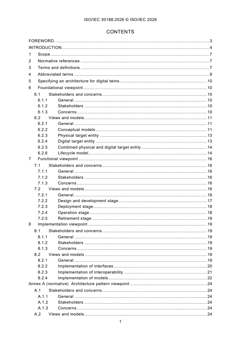
CONTENTS
FOREWORD . 3
INTRODUCTION . 4
1 Scope . 7
2 Normative references . 7
3 Terms and definitions . 7
4 Abbreviated terms . 9
5 Specifying an architecture for digital twins . 10
6 Foundational viewpoint . 10
6.1 Stakeholders and concerns . 10
6.1.1 General . 10
6.1.2 Stakeholders . 10
6.1.3 Concerns . 10
6.2 Views and models . 11
6.2.1 General . 11
6.2.2 Conceptual models . 11
6.2.3 Physical target entity . 13
6.2.4 Digital target entity . 13
6.2.5 Combined physical and digital target entity . 14
6.2.6 Lifecycle model . 14
7 Functional viewpoint . 16
7.1 Stakeholders and concerns . 16
7.1.1 General . 16
7.1.2 Stakeholders . 16
7.1.3 Concerns . 16
7.2 Views and models . 16
7.2.1 General . 16
7.2.2 Design and development stage . 17
7.2.3 Deployment stage . 18
7.2.4 Operation stage . 18
7.2.5 Retirement stage . 19
8 Implementation viewpoint . 19
8.1 Stakeholders and concerns . 19
8.1.1 General . 19
8.1.2 Stakeholders . 19
8.1.3 Concerns . 19
8.2 Views and models . 19
8.2.1 General . 19
8.2.2 Implementation of interfaces . 20
8.2.3 Implementation of interoperability . 21
8.2.4 Implementation of models . 22
Annex A (normative) Architecture pattern viewpoint . 24
A.1 Stakeholders and concerns . 24
A.1.1 General . 24
A.1.2 Stakeholders . 24
A.1.3 Concerns . 24
A.2 Views and models . 24
A.2.1 General . 24
A.2.2 Construction model . 25
A.2.3 Using views and models from other reference architectures . 26
A.3 Examples of patterns . 27
A.3.1 Template . 27
A.3.2 Sensing and actuating pattern . 28
A.3.3 Smart manufacturing RAMI reference model pattern . 30
A.3.4 Maturity pattern . 31
A.3.5 Framework for manufacturing pattern . 32
Bibliography . 34
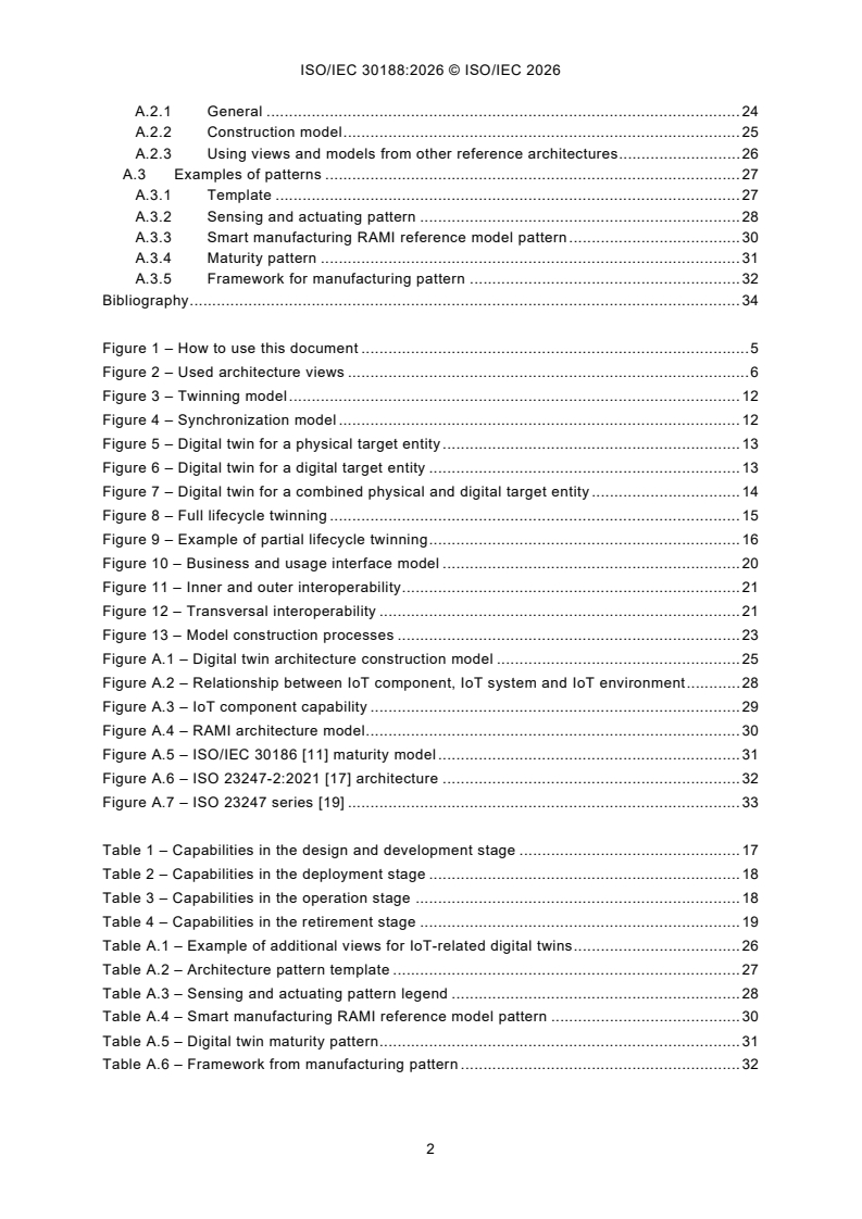
Figure 1 – How to use this document . 5
Figure 2 – Used architecture views . 6
Figure 3 – Twinning model . 12
Figure 4 – Synchronization model . 12
Figure 5 – Digital twin for a physical target entity . 13
Figure 6 – Digital twin for a digital target entity . 13
Figure 7 – Digital twin for a combined physical and digital target entity . 14
Figure 8 – Full lifecycle twinning . 15
Figure 9 – Example of partial lifecycle twinning . 16
Figure 10 – Business and usage interface model . 20
Figure 11 – Inner and outer interoperability . 21
Figure 12 – Transversal interoperability . 21
Figure 13 – Model construction processes . 23
Figure A.1 – Digital twin architecture construction model . 25
Figure A.2 – Relationship between IoT component, IoT system and IoT environment . 28
Figure A.3 – IoT component capability . 29
Figure A.4 – RAMI architecture model . 30
Figure A.5 – ISO/IEC 30186 [11] maturity model . 31
Figure A.6 – ISO 23247-2:2021 [17] architecture . 32
Figure A.7 – ISO 23247 series [19] . 33
Table 1 – Capabilities in the design and development stage . 17
Table 2 – Capabilities in the deployment stage . 18
Table 3 – Capabilities in the operation stage . 18
Table 4 – Capabilities in the retirement stage . 19
Table A.1 – Example of additional views for IoT-related digital twins . 26
Table A.2 – Architecture pattern template . 27
Table A.3 – Sensing and actuating pattern legend . 28
Table A.4 – Smart manufacturing RAMI reference model pattern . 30
Table A.5 – Digital twin maturity pattern . 31
Table A.6 – Framework from manufacturing pattern . 32
Digital twin - Reference architecture
FOREWORD
1) ISO (the International Organization for Standardization) and IEC (the International Electrotechnical Commission)
form the specialized system for worldwide standardization. National bodies that are members of ISO or IEC
participate in the development of International Standards through technical committees established by the
respective organization to deal with particular fields of technical activity. ISO and IEC technical committees
collaborate in fields of mutual interest. Other international organizations, governmental and non-governmental,
in liaison with ISO and IEC, also take part in the work.
2) The formal decisions or agreements of IEC and ISO on technical matters express, as nearly as possible, an
international consensus of opinion on the relevant subjects since each technical committee has representation
from all interested IEC and ISO National bodies.
3) IEC and ISO documents have the form of recommendations for international use and are accepted by IEC and
ISO National bodies in that sense. While all reasonable efforts are made to ensure that the technical content of
IEC and ISO documents is accurate, IEC and ISO cannot be held responsible for the way in which they are used
or for any misinterpretation by any end user.
4) In order to promote international uniformity, IEC and ISO National bodies undertake to apply IEC and
ISO documents transparently to the maximum extent possible in their national and regional publications. Any
divergence between any IEC and ISO document and the corresponding national or regional publication shall be
clearly indicated in the latter.
5) IEC and ISO do not provide any attestation of conformity. Independent certification bodies provide conformity
assessment services and, in some areas, access to IEC and ISO marks of conformity. IEC and ISO are not
responsible for any services carried out by independent certification bodies.
6) All users should ensure that they have the latest edition of this document.
7) No liability shall attach to IEC and ISO or their directors, employees, servants or agents including individual
experts and members of its technical committees and IEC and ISO National bodies for any personal injury,
property damage or other damage of any nature whatsoever, whether direct or indirect, or for costs (including
legal fees) and expenses arising out of the publication, use of, or reliance upon, this ISO/IEC document or any
other IEC and ISO documents.
8) Attention is drawn to the Normative references cited in this document. Use of the referenced publications is
indispensable for the correct application of this document.
9) IEC and ISO draw attention to the possibility that the implementation of this document may involve the use of (a)
patent(s). IEC and ISO take no position concerning the evidence, validity or applicability of any claimed patent
rights in respect thereof. As of the date of publication of this document, IEC and ISO had not received notice of
(a) patent(s), which may be required to implement this document. However, implementers are cautioned that this
may not represent the latest information, which may be obtained from the patent database available at
https://patents.iec.ch and www.iso.org/patents. IEC and ISO shall not be held responsible for identifying any or
all such patent rights.
ISO/IEC 30188 has been prepared by subcommittee 41: Internet of Things and Digital Twin, of
ISO/IEC joint technical committee 1: Information technology. It is an International Standard.
The text of this International Standard is based on the following documents:
Draft Report on voting
JTC1-SC41/598/FDIS JTC1-SC41/621/RVD
Full information on the voting for its approval can be found in the report on voting indicated in
the above table.
The language used for the development of this International Standard is English.
This document was drafted in accordance with ISO/IEC Directives, Part 2, and developed in
accordance with ISO/IEC Directives, Part 1, and the ISO/IEC Directives, JTC 1 Supplement
available at www.iec.ch/members_experts/refdocs and www.iso.org/directives.
INTRODUCTION
The term digital twin can be used to refer to a technology domain. This is the case in the title
of this document. Digital twin as a technology joins the real world and the digital world now
found in many domains of manufacturing, cities, agriculture, energy, buildings, healthcare, etc.,
and product categories such as appliances, automobiles, machine tools, and building security.
This technology is applied, for example, by the following:
– manufacturing companies to simulate and predict products and product lines, resulting in
production cycle reduction and cost reduction;
– city planners to optimize city development based on simulation models, and realize
visualization, convenience and intelligent city management;
– agricultural producers to monitor and optimize production operations, and perform predictive
diagnosis on agricultural machinery and equipment;
– energy managers to achieve visual monitoring and management of energy production and
transmission processes, as well as fault analysis and remote operation and maintenance;
– building operators to achieve energy conservation, environmental protection, lower
operation cost and intelligent management of constructed buildings;
– doctors to monitor patients' real-time conditions, providing personalized medical solutions,
dynamically optimizing medical resources.
Relevant application domains and standardization bodies for digital twin technology include,
among others, the following:
– smart energy with IEC TC 57, IEC SyC Smart Energy;
– smart cities with IEC SyC Smart Cities, ISO/TC 268, ISO/IEC JTC 1/WG 11;
– farming with ISO/TC 23/SC 19, ITU-T;
– building with ISO/TC 59/SC 13;
– healthcare with ISO/TC 215;
– manufacturing with ISO/TC 184/SC 4, IEC TC 65/JWG 21, IEC SyC Smart Manufacturing,
IEEE Computer Society Smart Manufacturing Standards Committee – Digital
Representation Working Group.
Specific technical areas and related standardization bodies for a digital twin include, among
others, the following:
– architecture (and lifecycle management) with ISO/IEC JTC 1/SC 7;
– modelling (and product properties) with ISO/IEC JTC 1/SC 7, ISO TC 184/SC 4,
IEC SC 3D;
– simulation with IEEE 1516, SISO (Simulation Interoperability Standards Organization);
– automatic identification (and data capture) with ISO/IEC JTC 1/SC 31;
– augmented reality and virtual reality with ISO/IEC JTC 1/AG 13, ISO/IEC JTC 1/SC 24,
IEEE P2048;
– Internet of Things with ISO/IEC JTC 1/SC 41;
– artificial intelligence with ISO/IEC JTC 1/SC 42;
– information technology security with ISO/IEC JTC 1/SC 27;
– privacy with ISO/IEC JTC 1/SC 27, and ISO/IEC JTC 1/SC 44;
– cloud computing with ISO/IEC JTC 1/SC 38.
The term digital twin can also be used to refer to the digital representation of a target entity.
This is the case in a reference architecture description of a system of interest which involves
digital twins.
Figure 1 depicts conceptual artefacts involved in the development of a system involving digital
twin technologies:
– input and output items (ellipses in Figure 1):
• stakeholder expectations and concerns as input, and
• the system involving digital twin technologies as output;
NOTE 1 Stakeholder expectations and concerns can include requirements for governance models.
– standard items (round rectangles in Figure 1) which enable architecture processes:
• ISO/IEC/IEEE 42010 [1] ,
• this document, and
• associated architecture patterns;
NOTE 2 Architecture patterns can include other reference architecture standards such as ISO/IEC 30141 [2].
– work product items or output of processes (rectangles in Figure 1):
• stakeholder needs and requirements,
• system requirements and
• the architecture description;
– processes (horizontal bars in Figure 1).
Figure 1 – How to use this document
___________
Numbers in square brackets refer to the Bibliography.
The target audience of this document are digital twin architects and engineers, digital twin
project or programme managers, digital twin business managers, or digital twin owners, of all
domains (application domains or technology domains).
Figure 2 shows the architecture views that are defined in this document:
– the foundational view covers the conceptual models (twinning model, synchronization
model) and the lifecycle model;
– the functional view covers capabilities in the design and development, the deployment, the
operation and the retirement stages;
– the implementation view covers the implementation of the usage and business interface, the
implementation of interoperability, and the implementation of models;
– the architecture pattern view covers the construction model which can be used to extend an
architecture.
Figure 2 – Used architecture views
NOTE 3 While this document focuses on reference architecture considerations related to digital twins, it does not
elaborate on concept relationships (e.g. digital twin as a technology, digital twin as a representation, digital twin in
a system).
NOTE 4 This document does not address security and privacy of digital twins. These can be addressed in specific
architecture patterns.
1 Scope
This document specifies a general reference architecture for a digital twin system in terms of
defining system fundamentals through the use of architecture views.
2 Normative references
There are no normative references in this document.
3 Terms and definitions
For the purposes of this document, the following terms and definitions apply.
ISO and IEC maintain terminology databases for use in standardization at the following
addresses:
– IEC Electropedia: available at https://www.electropedia.org/
– ISO Online browsing platform: available at https://www.iso.org/obp
3.1
digital twin
DTw
digital representation of a target entity (3.2) with data connections that enable convergence at
an appropriate rate of synchronization between the state of the target entity and the state of
that digital representation
Note 1 to entry: Digital twin has some or all of the capabilities of connection, integration, analysis, simulation,
visualization, optimization, collaboration, etc.
Note 2 to entry: Digital twin can provide an integrated view throughout the lifecycle of the target entity.
[SOURCE: ISO/IEC 30173:2023 [3], 3.1.1, modified – In the definition, "between the physical
and digital states" has been replaced with "between the state of the target entity and the state
of that digital representation" and the word order has been modified.]
3.2
target entity
entity (3.11) that is of interest for a digital twin (3.1)
Note 1 to entry: The target entity can be physical, digital, or both.
3.3
entity of interest
subject of an architecture description
EXAMPLE Enterprise, organization, solution, system (including software systems), subsystem, process, business,
data (as a data item or data structure), application, information technology (as a collection), mission, product, service,
software item, hardware item, product line, family of systems, system of systems, collection of systems, collection of
applications.
Note 1 to entry: In this document, the term entity of interest refers to the entity whose architecture is under
consideration in the preparation of an architecture description.
Note 2 to entry: This document distinguishes the entity of interest from other entities which are not the subject of
the architecture description.
Note 3 to entry: In this document, interest in an entity is intended to encompass interest in that entity’s environment,
lifecycle, architecture, requirements, design, implementation and operation. Such interests are captured via aspects,
concerns and stakeholder perspectives.
[SOURCE: ISO/IEC/IEEE 42010:2022 [1], 3.12]
3.4
architecture view
information part comprising portion of an architecture description
[SOURCE: ISO/IEC/IEEE 42010:2022 [1], 3.7, modified – The example has been deleted.]
3.5
architecture viewpoint
set of conventions for the creation, interpretation and use of an architecture view (3.4) to frame
one or more concerns
[SOURCE: ISO/IEC/IEEE 42010:2022 [1], 3.8, modified – The notes to entry have been
deleted.]
3.6
capability
measure of capacity and ability of an entity (3.11) (system, person or organization) to achieve
its objectives
[SOURCE: ISO/IEC TS 5723:2022 [4], 3.3.2, modified – In the definition, “and the ability” has
been replaced by “and ability”.]
3.7
observable entity
observable element
entity (3.11) in the environment (3.9) of the target entity (3.2) which can be observed and
modelled in the digital twin (3.1)
EXAMPLE 1 The human body is the observable entity of a healthcare digital twin.
EXAMPLE 2 An observable manufacturing element (e.g. personnel, equipment, material, process, facility,
environment, or product) is an observable entity.
Note 1 to entry: An observable entity can be physical or digital.
Note 2 to entry: A target entity is also a type of observable entity.
3.8
observation data
data resulting from the monitoring and measurement of an observable entity (3.7)
3.9
environment
context of surrounding things, conditions, or influences upon an entity (3.11)
Note 1 to entry: The environment of an entity of interest (3.3) includes external entities that can have various
influences upon an entity, such as developmental, technological, business, operational, organizational, political,
economic, legal, regulatory, ecological and social influences as well as external physical effects such as
electromagnetic radiation, charged particles, gravitational effects, and electric and magnetic fields.
Note 2 to entry: A label attached as a qualifier to the word environment identifies a particular sub-context within
that environment, such as development environment, test environment, and operational environment.
Note 3 to entry: “Influences upon” is a bi-directional relationship.
[SOURCE: ISO/IEC/IEEE 42010:2022 [1], 3.13, modified – Note 3 to entry has been added.]
3.10
architecture pattern
general, reusable solution to common architecture challenges encountered during the design
of an entity of interest (3.3)
Note 1 to entry: A reference architecture is a type of architecture pattern.
3.11
entity
anything perceivable or conceivable
[SOURCE: ISO 9000:2015 [5], 3.6.1, modified – The preferred terms "object" and "item", the
example and the note to entry have been deleted.]
3.12
system
arrangement of parts or elements that together exhibit a stated behaviour or meaning that the
individual constituents do not
[SOURCE:ISO/IEC/IEEE 15288:2023 [6], 3.46, modified – The notes to entry have been
deleted.]
3.13
stage
period within the lifecycle of an entity (3.11) that relates to the state of its description or
realization
Note 1 to entry: As used in this document, stages relate to major progress and achievement milestones of the entity
through its lifecycle.
Note 2 to entry: Stages often overlap.
[SOURCE: ISO/IEC/IEEE 15288:2023 [6], 3.43]
3.14
twinning
pairing a digital twin (3.1) with a target entity (3.2)
3.15
synchronization
action of making the states of digital twin (3.1) and target entity (3.2) synchronized
4 Abbreviated terms
AI artificial intelligence
DTw digital twin
IoT Internet of Things
IT information technology
OT operational technology
5 Specifying an architecture for digital twins
ISO/IEC/IEEE 42010 [1] provides requirements for the structure and expression of architecture
descriptions, including the following elements:
– architecture viewpoints;
– stakeholder concerns framed by those viewpoints;
– architecture views that address those concerns.
Architecture views convey aspects of an entity of interest that, together with other architecture
description elements, constitute the description of the architecture of the entity of interest.
As shown in Figure 2, this document covers the following architecture views:
– the foundational view that is required;
– the functional view that is required;
– the implementation view that is required;
– the architecture pattern view that is recommended.
6 Foundational viewpoint
6.1 Stakeholders and concerns
6.1.1 General
The foundational viewpoint establishes the fundamental concepts and essential characteristics
of the digital twins.
6.1.2 Stakeholders
– Software and system architect.
– Project or programme manager.
– Standards expert.
– People concerned with the fundamentals of digital twin.
– Domain experts.
– Business managers.
– System owner.
6.1.3 Concerns
The matters of relevance or importance to a stakeholder in a digital twin are the following:
– description of the interfaces with the target entity;
– description of the possible interactions between the digital twin and the target entity;
– description of the characteristics of the target entity that can be observed;
– description of the lifecycle dependencies between the digital twin and the target entity.
6.2 Views and models
6.2.1 General
The foundational viewpoint uses the following concepts:
– The concept of digital twin (DTw), a digital representation of a target entity which has the
following differentiating characteristics:
• it represents a target entity;
• data in the model is updated at an appropriate rate using observations of the target
entity;
• observation can be used to draw inferences about the target entity.
Optionally, a digital twin can provide an integrated view throughout the lifecycle of the target
entity.
– The concept of target entity, which can be a physical entity, a digital entity or a combination
of both.
– The concept of observable entity, an entity which can be observed in a particular context
within the environment of the target entity, and which can be modelled in the digital twin.
EXAMPLE 1 The target entity is a vehicle. Its environment includes the roadway infrastructure, the traffic and
weather conditions. Observable entities include the roadway, pedestrians, road hazards, ambient temperature and
moisture conditions, and nearby vehicles. A digital twin can provide models for driving conditions.
EXAMPLE 2 The target entity is a vehicle. The environment includes both the maintenance context and the
navigation service context of the vehicle manufacturer. One digital twin provides models for diagnosis and
maintenance, and another digital twin provides navigation support.
EXAMPLE 3 The target entity is a smart city economy. Observable entities are statistics on the smart city. The
digital twin is a smart city economic model. The digital twin synchronizes with the target entity through observation
data.
NOTE Some domains use the term asset instead of target entity.
6.2.2 Conceptual models
6.2.2.1 Twinning model
Figure 3 shows the twinning model, which explains the relations between a digital twin and a
target entity:
– a target entity is twinned with one or more digital twins;
– a target entity is a type of observable entity;
– an observable entity includes characteristics or properties that can be observed;
– a digital twin makes use of observation data on the characteristics or properties of a target
entity during its lifecycle;
– a digital twin accesses observation data through one or more data connection interfaces;
– data connection is ensured by interfaces, which can be physical interfaces, digital
interfaces, or both.
NOTE A target entity can consist of one or more observable entities in an environment, as the combination of
several observable entities is also an observable entity. The system boundaries of a target entity determine the
interface capabilities of a digital twin. They can be addressed in a usage view.
Figure 3 – Twinning model
6.2.2.2 Synchronization model
Figure 4 shows the synchronization model, which explains how synchronization can be
achieved between the state of the digital twin and the state of the target entity:
– a digital twin consists of one or more models;
– prediction functions use the models to process observation data, to generate predictions
about the target entity, to modify the state of the digital twin.
NOTE 1 Modelling functions can include artificial intelligence (AI) capabilities.
NOTE 2 Observation data can consist of single observations or continuously collected data.
Figure 4 – Synchronization model
6.2.3 Physical target entity
A physical target entity is a target entity which has physical characteristics and properties to
observe. Figure 5 shows a configuration for a digital twin twinned with a physical target entity.
It includes an interface to a data connection consisting of sensors and actuators.
EXAMPLE A digital twin for the human body (the physical target entity) using health sensors as the physical
interface.
Figure 5 – Digital twin for a physical target entity
6.2.4 Digital target entity
A digital target entity is a target entity which has digital characteristics and properties to observe.
Figure 6 shows a configuration for a digital twin with a digital target entity. It includes an
interface to a data connection consisting of a digital interface.
EXAMPLE A financial prediction digital twin of a local tax management system in a city (the digital target entity)
uses a privacy preserving digital interface.
Figure 6 – Digital twin for a digital target entity
6.2.5 Combined physical and digital target entity
A combined physical and digital target entity is a target entity which has physical and digital
characteristics and properties to observe. Figure 7 shows a configuration for a digital twin with
a combined physical and digital target entity. It includes an interface to a data connection
consisting of a physical interface and a digital interface.
EXAMPLE A vehicle digital twin that uses physical interfaces (sensors) to detect obstacles and digital interfaces to
support autonomous driving functions.
Figure 7 – Digital twin for a combined physical and digital target entity
6.2.6 Lifecycle model
6.2.6.1 General
The lifecycle model describes the dependencies between a target entity and a digital twin in
terms of state synchronization throughout the lifecycle of the target entity and of the digital twin.
NOTE 1 Lifecycle management is addressed in ISO/IEC/IEEE 24748-1 [7].
Synchronization between a target entity and its digital twin can occur during every lifecycle
stage. Some digital twins are paired with a target entity as part of that entity’s conceptualization,
whereas other digital twins can occur later in the lifecycle of the target entity. Some digital twins
leave service before their target entity is retired. Synchronization can occur at a different
frequency as the relationship between the target entity and digital twin matures.
Synchronization can be continuous, periodic, event-driven and span over several lifecycle
stages.
EXAMPLE 1 A large oil refinery introduces a digital twin after the physical refinery has been running for years, in
order to simulate certain scenarios for reducing emissions. This is a brownfield approach (introducing a digital twin
after system is in operation).
EXAMPLE 2 A machine manufacturer designs a system, using three-dimensional (3D) drawings to make and run
the model in 3D before they even bend a piece of metal to physically make the machine. This is a greenfield approach.
NOTE 2 For certain use cases, a brownfield approach can be more challenging than a greenfield approach because
of the cost of realizing synchronization.
NOTE 3 Synchronization requirements depend on requirements and domain concerns including quality of service,
and real-time constraints.
6.2.6.2 Full lifecycle twinning
Figure 8 shows a lifecycle model in which:
– the target entity and the digital twin have a common stage – design and development;
– the target entity and the digital twin have separate lifecycle stages – deployment, operation
and retirement; and
– state synchronization takes place during the separate stages.
NOTE A digital twin and a target entity can be developed and operated by separate organizations.
Figure 8 – Full lifecycle twinning
6.2.6.3 Partial lifecycle twinning
Figure 9 shows a lifecycle model focusing on the lifecycle of the target entity, where a digital
twin entity is twinned at a specific stage, such as the operation stage.
This model is appropriate when some specific digital twin services are needed.
EXAMPLE 1 A digital twin dedicated to maintenance is used to manage the update of the target entity.
EXAMPLE 2 A manufacturing and assembling digital twin.
EXAMPLE 3 A predictive maintenance digital twin.
EXAMPLE 4 A performance optimization digital twin.
EXAMPLE 5 An end-of-life and decommissioning digital twin.
Figure 9 – Example of partial lifecycle twinning
7 Functional viewpoint
7.1 Stakeholders and concerns
7.1.1 General
The functional viewpoint provides a description of digital twin capabilities.
7.1.2 Stakeholders
– Architect.
– Project or programme manager.
– Standards expert and people concerned with the fundamentals of digital twin.
– Domain experts.
– Business managers.
– System owners.
7.1.3 Concerns
What are the capabilities of a digital twin?
7.2 Views and models
7.2.1 General
Digital twin capabilities depend on the lifecycle stage of the digital twin. Examples are listed in
7.2.2 for the design and development stage, in 7.2.3 for the deployment stage, in 7.2.4 for the
operation stage, and in 7.2.5 for the retirement stage. These capabilities are further listed
according to the following categories: definition, execution, monitoring and measurement,
analysis, control, and optimization.
NOTE 1 Monitoring is about collecting data to obtain qualitative or quantitative information, whereas measurement
is to obtain quantitative information.
NOTE 2 Capabilities for security and privacy of digital twins are not covered in the functional viewpoint. They can
be addressed through additional viewpoints using Annex A.
Upon inception, the following outcomes are assumed:
– business process profiles have been specified;
– goals and needs have been defined.
NOTE 3 Needs can cover a governance framework, such as roles, responsibilities and oversight mechanisms. They
can include organizational capabilities such as compliance checking, auditing, or ethical oversights.
7.2.2 Design and development stage
The capabilities in the design and development stage are listed in Table 1.
Table 1 – Capabilities in the design and development stage
Category Examples of capability
Model design
System design (e.g. digital thread design in the field of smart manufacturing as defined in
ISO 23247-5 [8]
Definition
Cyber-physical system design
Model training
Simulation
Assistance on selection of tools, techniques and data
Artificial intelligence support (e.g. large language model, machine learning, deep learning,
Execution
rule-based approaches)
Digital twin continuous improvement
Visual design
Simulation of digital twin implementation process
Visual monitoring
Monitoring and
Safety check
measurement
Health check
Counterfeit detection
Security and privacy checks
Support to understanding and analysis of physical entities
Analysis
Upgrade analysis
Support for system cost reduction
Control
Upgrade analysis
Tools to support optimization analysis (e.g. geometry modelling, kinematics)
Support for design optimization
Support for operation costs reduction
Optimization Prediction prognosis
Sustainability
Support for user experience enhancement
Reduction of carbon emission
7.2.3 Deployment stage
The capabilities in the deployment stage are listed in Table 2.
Table 2 – Capabilities in the deployment stage
Category Examples of capability
Definition Modelling and simulation
Execution Assistance on use of tools, technology, and data
Monitoring and
Visualization upgrade
measurement
Support to analyse generated data and simulation results
Analysis
Support to evaluate existing physical entities
Support for integration of control equipment, systems, environments, etc.
Control
Support for system cost reduction
Optimization Support for efficient implementation
7.2.4 Operation stage
The capabilities in the operation stage are listed in Table 3.
Table 3 – Capabilities in the operation stage
Category Examples of capability
Definition Full interaction with physical entities
Platform construction
Execution Interoperability support
Client availability support
Monitoring and
Timely, real-time and visual accounting and measurement
measurement
Cost estimation
Failure analysis
Analysis
Material management
Operational trade-off analysis
Alarming
Repairing support
Calibrating
Control
Inventory management
Troubleshooting support
Planning
Support for operation costs reduction
Prediction prognosis
Optimization Sustainability
Support for user experience enhancement
Support for carbon emission reduction
7.2.5 Retirement stage
The capabilities in the retirement stage are listed in Table 4.
Table 4 – Capabilities in the retirement stage
Category Examples of capability
Definition Replacement by other digital twins
Execution Historical database construction
Historical data to be used for education and training
Monitoring and
measurement
Visualization practice and rehearsal
Archiving support for scientific research
Analysis
Technical support provision
Control Archiving
Optimization Support for use in other applications
8 Implementation viewpoint
8.1 Stakeholders and concerns
8.1.1 General
This viewpoint frames further concerns related to the implementation of a digital twin in terms
of
– usa
...