


ISO/FDIS 10328
(Main)Prosthetics — Structural testing of lower-limb prostheses — Requirements and test methods
General Information
- Abstract
IMPORTANT - ISO 10328:2016 is suitable for the assessment of the conformity of lower limb prosthetic devices/structures with the strength requirements specified in 4.4 of ISO 22523:2006 (see NOTE 1). Prosthetic ankle-foot devices and foot units on the market, which have demonstrated their compliance with the strength requirements specified in 4.4 of ISO 22523:2006 through submission to the relevant tests of ISO 10328:2006, need not be retested to ISO 22675:2016. WARNING - ISO 10328:2016 is not suitable to serve as a guide for the selection of a specific lower limb prosthetic device/structure in the prescription of an individual lower limb prosthesis! Any disregard of this warning can result in a safety risk for amputees. ISO 10328:2016 specifies procedures for static and cyclic strength tests on lower-limb prostheses (see NOTE 2) which typically produce compound loadings by the application of a single test force. The compound loads in the test sample relate to the peak values of the components of loading which normally occur at different instants during the stance phase of walking.
- Status
- Not Published
- Technical Committee
- ISO/TC 168 - Prosthetics and orthotics
- Drafting Committee
- ISO/TC 168 - Prosthetics and orthotics
- Current Stage
- 5020 - FDIS ballot initiated: 2 months. Proof sent to secretariat
- Start Date
- 07-Aug-2026
- Completion Date
- 07-Aug-2026
Buy Documents

ISO/FDIS 10328 - Prosthetics — Structural testing of lower-limb prostheses — Requirements and test methods
REDLINE ISO/FDIS 10328 - Prosthetics — Structural testing of lower-limb prostheses — Requirements and test methods

ISO/FDIS 10328 - Prothèses — Essais portant sur la structure des prothèses de membres inférieurs — Exigences et méthodes d’essai
Overview
ISO/FDIS 10328:2026 – Prosthetics - Structural testing of lower-limb prostheses - Requirements and test methods – is an International Standard developed by ISO/TC 168, targeting quality assurance in lower-limb prosthetic devices. This document defines the standardized procedures for conducting structural tests on lower-limb prostheses, focusing on both static and cyclic strength. The primary aim is to assess devices for compliance with essential strength and safety requirements, avoiding potential risks for users.
This standard provides a comprehensive framework for evaluating lower-limb prosthetic devices, particularly aligned with the strength requirements specified in ISO 22523:2006. It is important to note that this document is not intended as a guide for the selection or prescription of devices for individual patients, as such use could pose safety risks.
Key Topics
- Scope of Testing: Specifies static and cyclic strength tests to simulate peak and repetitive loads experienced during walking.
- Test Ranges & Loading Profiles: Introduces Test Ranges based on intended prosthesis use, reflecting real-life locomotion profiles.
- Test Procedures: Covers principal static and cyclic tests, torsion tests, and tests specific to components like ankle-foot devices and knee joints.
- Performance Categories: Addresses proof strength, ultimate strength, fatigue strength, and torsional strength – each with corresponding test methods and criteria.
- Sample Selection & Test Configuration: Guides on test sample preparation, alignment, and configuration within a defined three-dimensional coordinate system.
- Safety & Conformity: Outlines procedures for demonstrating device conformity with international safety benchmarks.
- Reporting & Documentation: Details requirements for lab logs and test reports, ensuring traceability and repeatability.
- Design Changes: Stipulates the need to repeat tests and field evaluations following significant changes in design or materials.
Applications
ISO/FDIS 10328:2026 is highly relevant to:
- Manufacturers of Lower-Limb Prostheses: Ensures prosthetic devices and components are rigorously tested for strength, durability, and safety, fostering market confidence and regulatory compliance.
- Testing Laboratories: Provides standardized methods for assessing prosthesis performance, including static, cyclic, and torsion tests.
- Regulatory Bodies: Supports assessment and certification processes related to medical device safety and performance requirements.
- Researchers & Developers: Offers a framework for consistent benchmarking during product development and innovation in prosthetic technology.
- Quality Assurance & Compliance Professionals: Serves as a reference for evaluating product conformity before market release.
By enforcing harmonized testing and reporting, this standard helps improve patient safety and device reliability in real-world use.
Related Standards
For comprehensive prosthetic device assessment, the following related ISO standards should be considered:
- ISO 22523:2006 – External limb prostheses and external orthoses - Requirements and test methods
- ISO 8549-1 – Prosthetics and orthotics - Vocabulary - Part 1: General terms for external limb prostheses and external orthoses
- ISO 15223-1 – Medical devices - Symbols to be used with information to be supplied by the manufacturer
- ISO 15032 – Prostheses - Structural testing of hip units
- IEC 60417 – Graphical symbols for use on equipment
These standards, when used in concert with ISO 10328, create a robust foundation for the design, assessment, and quality assurance of lower-limb prosthetic devices.
Keywords: ISO 10328, lower-limb prostheses, structural testing, prosthetic device standard, cyclic test, static test, strength requirements, conformity assessment, ISO 22523, medical device testing.
Relations
- Effective Date
- 12-Feb-2026
- Effective Date
- 29-Apr-2023
Buy Documents
ISO/FDIS 10328 - Prosthetics — Structural testing of lower-limb prostheses — Requirements and test methods
REDLINE ISO/FDIS 10328 - Prosthetics — Structural testing of lower-limb prostheses — Requirements and test methods
ISO/FDIS 10328 - Prothèses — Essais portant sur la structure des prothèses de membres inférieurs — Exigences et méthodes d’essai
Get Certified
Connect with accredited certification bodies for this standard

BSI Group
BSI (British Standards Institution) is the business standards company that helps organizations make excellence a habit.

TÜV Rheinland
TÜV Rheinland is a leading international provider of technical services.

TÜV SÜD
TÜV SÜD is a trusted partner of choice for safety, security and sustainability solutions.
Sponsored listings
Frequently Asked Questions
ISO/FDIS 10328 is a draft published by the International Organization for Standardization (ISO). Its full title is "Prosthetics — Structural testing of lower-limb prostheses — Requirements and test methods". This standard covers: IMPORTANT - ISO 10328:2016 is suitable for the assessment of the conformity of lower limb prosthetic devices/structures with the strength requirements specified in 4.4 of ISO 22523:2006 (see NOTE 1). Prosthetic ankle-foot devices and foot units on the market, which have demonstrated their compliance with the strength requirements specified in 4.4 of ISO 22523:2006 through submission to the relevant tests of ISO 10328:2006, need not be retested to ISO 22675:2016. WARNING - ISO 10328:2016 is not suitable to serve as a guide for the selection of a specific lower limb prosthetic device/structure in the prescription of an individual lower limb prosthesis! Any disregard of this warning can result in a safety risk for amputees. ISO 10328:2016 specifies procedures for static and cyclic strength tests on lower-limb prostheses (see NOTE 2) which typically produce compound loadings by the application of a single test force. The compound loads in the test sample relate to the peak values of the components of loading which normally occur at different instants during the stance phase of walking.
IMPORTANT - ISO 10328:2016 is suitable for the assessment of the conformity of lower limb prosthetic devices/structures with the strength requirements specified in 4.4 of ISO 22523:2006 (see NOTE 1). Prosthetic ankle-foot devices and foot units on the market, which have demonstrated their compliance with the strength requirements specified in 4.4 of ISO 22523:2006 through submission to the relevant tests of ISO 10328:2006, need not be retested to ISO 22675:2016. WARNING - ISO 10328:2016 is not suitable to serve as a guide for the selection of a specific lower limb prosthetic device/structure in the prescription of an individual lower limb prosthesis! Any disregard of this warning can result in a safety risk for amputees. ISO 10328:2016 specifies procedures for static and cyclic strength tests on lower-limb prostheses (see NOTE 2) which typically produce compound loadings by the application of a single test force. The compound loads in the test sample relate to the peak values of the components of loading which normally occur at different instants during the stance phase of walking.
ISO/FDIS 10328 is classified under the following ICS (International Classification for Standards) categories: 11.040.40 - Implants for surgery, prosthetics and orthotics. The ICS classification helps identify the subject area and facilitates finding related standards.
ISO/FDIS 10328 has the following relationships with other standards: It is inter standard links to FprEN ISO 10328, ISO 10328:2016. Understanding these relationships helps ensure you are using the most current and applicable version of the standard.
ISO/FDIS 10328 is available in PDF format for immediate download after purchase. The document can be added to your cart and obtained through the secure checkout process. Digital delivery ensures instant access to the complete standard document.
Standards Content (Sample)
FINAL DRAFT
International
Standard
ISO/TC 168
Prosthetics — Structural testing
Secretariat: DIN
of lower-limb prostheses —
Voting begins on:
Requirements and test methods
2026-08-07
Prothèses — Essais portant sur la structure des prothèses de
Voting terminates on:
membres inférieurs — Exigences et méthodes d’essai
2026-10-02
RECIPIENTS OF THIS DRAFT ARE INVITED TO SUBMIT,
WITH THEIR COMMENTS, NOTIFICATION OF ANY
RELEVANT PATENT RIGHTS OF WHICH THEY ARE AWARE
AND TO PROVIDE SUPPOR TING DOCUMENTATION.
IN ADDITION TO THEIR EVALUATION AS
BEING ACCEPTABLE FOR INDUSTRIAL, TECHNO
ISO/CEN PARALLEL PROCESSING LOGICAL, COMMERCIAL AND USER PURPOSES, DRAFT
INTERNATIONAL STANDARDS MAY ON OCCASION HAVE
TO BE CONSIDERED IN THE LIGHT OF THEIR POTENTIAL
TO BECOME STAN DARDS TO WHICH REFERENCE MAY BE
MADE IN NATIONAL REGULATIONS.
Reference number
FINAL DRAFT
International
Standard
ISO/TC 168
Prosthetics — Structural testing
Secretariat: DIN
of lower-limb prostheses —
Voting begins on:
Requirements and test methods
Prothèses — Essais portant sur la structure des prothèses de
Voting terminates on:
membres inférieurs — Exigences et méthodes d’essai
RECIPIENTS OF THIS DRAFT ARE INVITED TO SUBMIT,
WITH THEIR COMMENTS, NOTIFICATION OF ANY
RELEVANT PATENT RIGHTS OF WHICH THEY ARE AWARE
AND TO PROVIDE SUPPOR TING DOCUMENTATION.
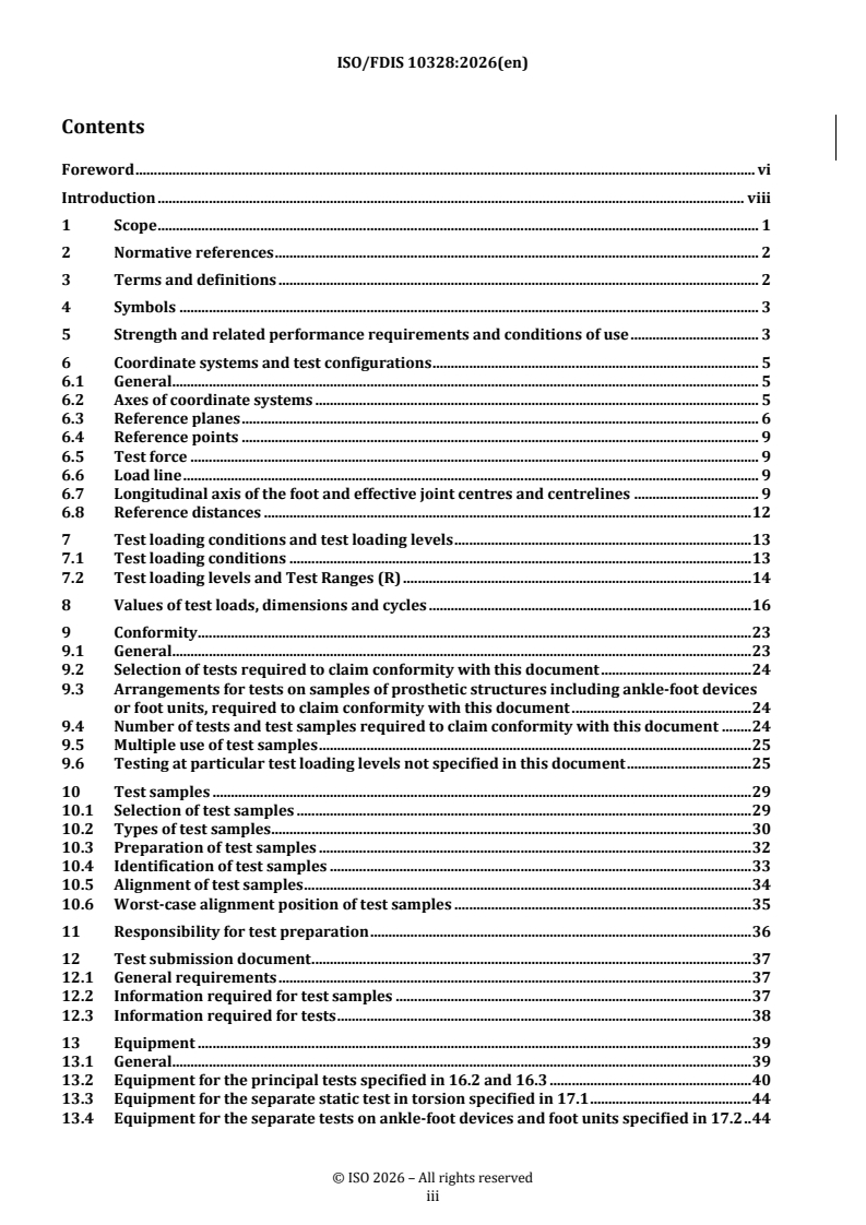
© ISO 2026
IN ADDITION TO THEIR EVALUATION AS
All rights reserved. Unless otherwise specified, or required in the context of its implementation, no part of this publication may
BEING ACCEPTABLE FOR INDUSTRIAL, TECHNO
ISO/CEN PARALLEL PROCESSING
LOGICAL, COMMERCIAL AND USER PURPOSES, DRAFT
be reproduced or utilized otherwise in any form or by any means, electronic or mechanical, including photocopying, or posting on
INTERNATIONAL STANDARDS MAY ON OCCASION HAVE
the internet or an intranet, without prior written permission. Permission can be requested from either ISO at the address below
TO BE CONSIDERED IN THE LIGHT OF THEIR POTENTIAL
or ISO’s member body in the country of the requester.
TO BECOME STAN DARDS TO WHICH REFERENCE MAY BE
MADE IN NATIONAL REGULATIONS.
ISO copyright office
CP 401 • Ch. de Blandonnet 8
CH-1214 Vernier, Geneva
Phone: +41 22 749 01 11
Email: copyright@iso.org
Website: www.iso.org
Published in Switzerland Reference number
ii
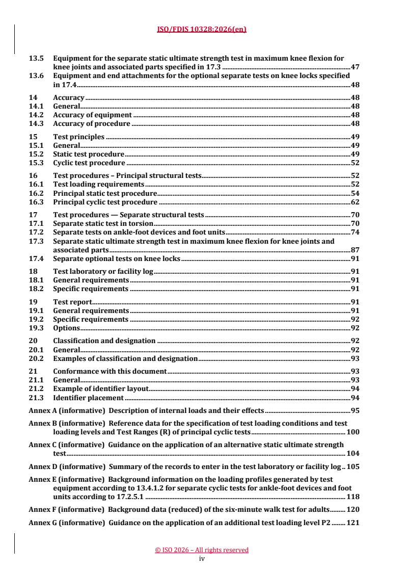
Contents Page
Foreword .vii
Introduction .ix
1 Scope . 1
2 Normative references . 2
3 Terms and definitions . 2
4 Symbols . 3
5 Strength and related performance requirements and conditions of use . 3
6 Coordinate systems and test configurations . 5
6.1 General .5
6.2 Axes of coordinate systems.5
6.3 Reference planes .5
6.3.1 General .5
6.3.2 Top reference plane, T.5
6.3.3 Knee reference plane, K .5
6.3.4 Ankle reference plane, A .6
6.3.5 Bottom reference plane, B . .6
6.4 Reference points.7
6.5 Test force . .8
6.6 Load line .8
6.7 Longitudinal axis of the foot and effective joint centres and centrelines .8
6.7.1 General .8
6.7.2 Longitudinal axis of the foot .8
6.7.3 Effective ankle-joint centre .8
6.7.4 Effective ankle-joint centreline .10
6.7.5 Effective knee-joint centreline . .10
6.7.6 Effective knee-joint centre .11
6.8 Reference distances .11
6.8.1 Offsets .11
6.8.2 Combined offsets .11
6.8.3 Effective lever arms L and L .11
A K
6.8.4 Distance L .11
BT
7 Test loading conditions and test loading levels .11
7.1 Test loading conditions .11
7.1.1 General .11
7.1.2 Test loading conditions of principal structural tests . 12
7.1.3 Test loading conditions of separate structural tests . 12
7.2 Test loading levels and Test Ranges (R) . 12
8 Values of test loads, dimensions and cycles . 14
9 Conformity . .20
9.1 General . 20
9.2 Selection of tests required to claim conformity with this document . 20
9.3 Arrangements for tests on samples of prosthetic structures including ankle-foot
devices or foot units, required to claim conformity with this document . 20
9.3.1 General . 20
9.3.2 Particular arrangements concerning the ankle-foot device or foot unit . 20
9.3.3 Particular arrangements and requirements concerning the part required to
connect the ankle-foot device or foot unit to the remainder of the prosthetic
structure .21
9.4 Number of tests and test samples required to claim conformity with this document .21
9.5 Multiple use of test samples . .21
9.5.1 General .21
iii
9.5.2 Restriction . 22
9.6 Testing at particular test loading levels not specified in this document . 22
10 Test samples .24
10.1 Selection of test samples .24
10.1.1 General .24
10.1.2 Selection of ankle-foot devices and foot units of appropriate size of foot . 25
10.2 Types of test samples . 26
10.2.1 Complete structure . 26
10.2.2 Partial structure . 28
10.2.3 Any other structure . 28
10.3 Preparation of test samples . 28
10.4 Identification of test samples . 29
10.5 Alignment of test samples . 30
10.5.1 Test samples for principal tests and optional separate tests on knee locks . 30
10.5.2 Test samples for separate tests on ankle-foot devices and foot units . 30
10.5.3 Test samples for separate static ultimate strength tests in maximum knee
flexion for knee joints and associated parts . 30
10.6 Worst-case alignment position of test samples .31
11 Responsibility for test preparation .32
12 Test submission document . .33
12.1 General requirements . 33
12.2 Information required for test samples . 33
12.2.1 All test samples . 33
12.2.2 Test samples for tests on ankle-foot devices and foot units . 34
12.2.3 Test samples for static ultimate strength tests in maximum knee flexion for
knee joints and associated parts . 34
12.3 Information required for tests . 34
12.3.1 General . 34
12.3.2 For all tests . 34
12.3.3 For static tests in torsion and on ankle-foot devices and foot units . 34
12.3.4 For static ultimate strength tests . 35
12.3.5 For cyclic tests . 35
12.3.6 For tests in torsion . 35
12.3.7 For tests on ankle-foot devices and foot units . 35
13 Equipment .35
13.1 General . 35
13.2 Equipment for the principal tests specified in 16.2 and 16.3 . 36
13.2.1 End attachments . 36
13.2.2 Jig (optional) . 38
13.2.3 Test equipment . 38
13.3 Equipment for the separate static test in torsion specified in 17.1 . 40
13.3.1 Test equipment . 40
13.4 Equipment for the separate tests on ankle-foot devices and foot units specified in 17.2 . 40
13.4.1 Test equipment . 40
13.5 Equipment for the separate static ultimate strength test in maximum knee flexion for
knee joints and associated parts specified in 17.3 . 44
13.5.1 Extension pieces . 44
13.5.2 Test equipment to perform static compression loading (Compression testing
machine or other equipment) . 44
13.6 Equipment and end attachments for the optional separate tests on knee locks specified
in 17.4 . 44
14 Accuracy .44
14.1 General . 44
14.2 Accuracy of equipment . 44
14.3 Accuracy of procedure .45
15 Test principles .45
iv
15.1 General .45
15.2 Static test procedure .45
15.3 Cyclic test procedure . 48
16 Test procedures – Principal structural tests .48
16.1 Test loading requirements . 48
16.1.1 Preparation for test loading . 48
16.1.2 Application of test loading . 48
16.2 Principal static test procedure . . 50
16.2.1 Principal static proof test . 50
16.2.2 Principal static ultimate strength test . 55
16.3 Principal cyclic test procedure .57
16.3.1 General requirements .57
16.3.2 Test method . 58
16.3.3 Performance requirements . .62
16.3.4 Conformance conditions .62
17 Test procedures — Separate structural tests .65
17.1 Separate static test in torsion . 65
17.1.1 General . 65
17.1.2 Purpose of test . 66
17.1.3 Test method . 66
17.1.4 Performance requirements . . 68
17.1.5 Conformity conditions . 68
17.2 Separate tests on ankle-foot devices and foot units . 69
17.2.1 General . 69
17.2.2 Purpose of tests .70
17.2.3 Separate static proof test for ankle-foot devices and foot units .70
17.2.4 Separate static ultimate strength test for ankle-foot devices and foot units . 72
17.2.5 Separate cyclic test for ankle-foot devices and foot units .76
17.3 Separate static ultimate strength test in maximum knee flexion for knee joints and
associated parts . 81
17.3.1 General . 81
17.3.2 Purpose of test . 82
17.3.3 Applicability of the test to specific test samples. 82
17.3.4 Test method . 82
17.3.5 Performance requirement . 83
17.3.6 Conformance conditions . 83
17.4 Separate optional tests on knee locks . 84
17.4.1 General . 84
17.4.2 Purpose of tests . 84
18 Test laboratory or facility log . .85
18.1 General requirements . 85
18.2 Specific requirements . 85
19 Test report .85
19.1 General requirements . 85
19.2 Specific requirements . 86
19.3 Options. 86
20 Classification and designation .86
20.1 General . 86
20.2 Examples of classification and designation . 86
21 Conformance with this document .87
21.1 General . 87
21.2 Example of identifier layout . 87
21.3 Identifier placement . 87
Annex A (informative) Description of internal loads and their effects .88
v
Annex B (informative) Reference data for the specification of test loading conditions and test
loading levels and Test Ranges (R) of principal cyclic tests .92
Annex C (informative) Guidance on the application of an alternative static ultimate strength
test .96
Annex D (informative) Summary of the records to enter in the test laboratory or facility log .97
Annex E (informative) Background information on the loading profiles generated by test
equipment according to 13.4.1.2 for separate cyclic tests for ankle-foot devices and foot
units according to 17.2.5.1 .108
Annex F (informative) Background data (reduced) of the six-minute walk test for adults .110
Annex G (informative) Guidance on the application of an additional test loading level P2 .111
Annex H (informative) Alternative test geometry for loading condition I and II derived from
recent biomechanical studies .115
Annex ZA (informative) Relationship between this European standard and the General Safety
and Performance Requirements of Regulation (EU) 2017/745 aimed to be covered .117
Bibliography .120
vi
Foreword
ISO (the International Organization for Standardization) is a worldwide federation of national standards
bodies (ISO member bodies). The work of preparing International Standards is normally carried out through
ISO technical committees. Each member body interested in a subject for which a technical committee
has been established has the right to be represented on that committee. International organizations,
governmental and non-governmental, in liaison with ISO, also take part in the work. ISO collaborates closely
with the International Electrotechnical Commission (IEC) on all matters of electrotechnical standardization.
The procedures used to develop this document and those intended for its further maintenance are described
in the ISO/IEC Directives, Part 1. In particular, the different approval criteria needed for the different types
of ISO documents should be noted. This document was drafted in accordance with the editorial rules of the
ISO/IEC Directives, Part 2 (see www.iso.org/directives).
ISO draws attention to the possibility that the implementation of this document may involve the use of patent.
ISO takes no position concerning the evidence, validity or applicability of any claimed patent rights in respect
thereof. As of the date of publication of this document, ISO had not received notice of patents which may be
required to implement this document. However, implementers are cautioned that this may not represent the
latest information, which may be obtained from the patent database available at www.iso.org/patents. ISO
shall not be held responsible for identifying any or all such patent rights.
Any trade name used in this document is information given for the convenience of users and does not
constitute an endorsement.
For an explanation of the voluntary nature of standards, the meaning of ISO specific terms and expressions
related to conformity assessment, as well as information about ISO’s adherence to the World Trade
Organization (WTO) principles in the Technical Barriers to Trade (TBT), see www.iso.org/iso/foreword.html.
This document was prepared by Technical Committee ISO/TC 168, Prosthetics and orthotics, in collaboration
with the European Committee for Standardization (CEN) Technical Committee CEN/TC 293, Assistive
products and accessibility, in accordance with the Agreement on technical cooperation between ISO and CEN
(Vienna Agreement).
This third edition cancels and replaces the second edition (ISO 10328:2016), which has been technically
revised.
The main changes are as follows:
— Offsets for P3 and P4 are combined into the test offset for P5 in Table 6 and have been removed from
document. Geometry of the test setup has been revised by moving the outward offset at bottom reference
plane over the forward axis, resulting in the offset changing from ‒19 mm to +19 mm to align with results
from modern gait analysis. Outwards offsets knee and ankle have been adjusted accordingly.
— Test load levels P6 through P8 previously in former Annex D have been included in Tables 5, 8 and 11 and
the Annex removed from the document. Former Annex E and F have been renamed to Annex D and E and
references updated. Former Annex G has been removed. New Annex F, Annex G and Annex H have been
added.
— Test Ranges (R) for the strength test have been introduced, related to the intended use of the device. The
ranges differ by different loading factors, while tests load levels remain unchanged apart from rounding
and accommodation to changed offsets (see below).
— Test forces in Table 11 have been adjusted for P3 and P4.
— A method to analyse shock absorption capacity has been added, which eliminates the difficulty to decide
whether a device passes or fails above the ultimate static lower load level.
— Separate tests on knee locks are now optional tests and the test methods on separate tests on knee locks
have been removed from the document.
— Test geometry defined in this document is limited to 150 mm above knee-joint centre.
vii
— Clause 21 has been renamed to “Conformance to this document” and reference to Labelling has been
removed from the document.
— Table 1, Table 4, Table 5, Table 6, Table 7, Table 8, Table 9, Table 10 and Table 11 have been updated and
forces adjusted for new unified offsets.
— Table B.1, Table B.2, Table B.3 and Table B.4 have been updated.
— The rate of loading of between 100 N/s and 10 kN/s is now normative.
Any feedback or questions on this document should be directed to the user’s national standards body. A
complete listing of these bodies can be found at www.iso.org/members.html.
viii
Introduction
As a result of concern in the international community about the need to provide prostheses that are safe in
use, and also because of an awareness that test standards would assist the development of better prostheses,
a series of meetings was held under the aegis of the International Society for Prosthetics and Orthotics
(ISPO). The final one was held in Philadelphia, PA, USA in 1977 at which a preliminary consensus was
reached on methods of testing and the required load values. From 1979 onwards this and following work led
to the development of the ISO 10328:1996 series and consequent revisions. The test procedures might not be
applicable to prostheses of mechanical characteristics different from those used in the consensus.
During use, a prosthesis is subjected to a series of load actions, each varying individually with time. The test
methods specified in this document use static and cyclic strength tests which typically produce compound
loadings by the application of a single test force.
The static tests relate to the worst loads generated in any activity. The cyclic tests relate to normal walking
activities where loads occur regularly with each step. This document specifies fatigue testing of structural
components. The tests specified do not provide sufficient data to predict actual service life.
The evaluation of lower-limb prostheses and their components requires controlled field trials in addition to
the laboratory tests specified in this document.
The laboratory tests and field trials should be repeated when significant design changes are made to a load-
bearing part of a prosthesis.
Ideally, additional laboratory tests should be carried out to deal with function, wear and tear, new material
developments, environmental influences and user activities as part of the evaluation procedure. There are
no standards for such tests, so appropriate procedures will need to be determined.
ix
FINAL DRAFT International Standard ISO/FDIS 10328:2026(en)
Prosthetics — Structural testing of lower-limb prostheses —
Requirements and test methods
WARNING — This document is not suitable to serve as a guide for the selection of a specific lower
limb prosthetic device or structure in the prescription of an individual lower limb prosthesis. Any
disregard of this warning can result in a safety risk for amputees.
1 Scope
This document specifies procedures for static and cyclic strength tests on lower-limb prostheses (see
NOTE 2) which typically produce compound loadings by the application of a single test force. The compound
loads in the test sample relate to the peak values of the components of loading which normally occur at
different instants during the stance phase of walking.
This document specifies Test Ranges (R) by specifying locomotion profiles for the cyclic test in relation to
the intended use. According to the concept of the tests of this document, each sample of lower limb prosthetic
device or structure submitted for test is, nevertheless, free to develop its individual performance under load.
The tests described in this document comprise:
— principal static and cyclic tests for all components;
— a separate static test in torsion for all components;
— separate static and cyclic tests on ankle-foot devices and foot units for all ankle-foot devices as single
components including ankle units or ankle attachments and all foot units as single components;
— a separate static ultimate strength test in maximum knee flexion on knee joints and associated parts for
all knee units or knee-shin-assemblies and adjacent components that normally provide the flexion stop
on a complete prosthesis;
— optional separate tests on knee locks for all mechanisms which lock the knee joint in the extended
position of the knee unit or knee-shin-assembly.
The tests described in this document apply to specific types of ankle-disarticulation prostheses (see
NOTE 2), to transtibial (below-knee), knee-disarticulation and transfemoral (above-knee) prostheses and
to the distal (lower) part of hip-disarticulation and hemi-pelvectomy prostheses (see NOTE 3). The test
geometry described in this standard is only intended to be used up to a level of 150 mm above the knee-joint
centre.
This document is suitable for the assessment of the conformity of lower limb prosthetic devices or structures
with the strength requirements specified in ISO 22523:2006, 4.4 (see NOTE 1). Lower limb prosthetic devices
or structures on the market, which have demonstrated their compliance with the strength requirements
specified in ISO 22523:2006, 4.4 through submission to the relevant tests of ISO 22523:2006, need not be
retested to this document.
NOTE 1 The tests can be performed on complete structures, on part structures or on individual components.
NOTE 2 The tests only apply to ankle-disarticulation prostheses which include (foot) components of prosthetic
ankle-foot devices ta
...
ISO/TC 168
Secretariat: DIN
Date: 2026-03-0306-25
Prosthetics — Structural testing of lower-limb prostheses —
Requirements and test methods
Prothèses — Essais portant sur la structure des prothèses de membres inférieurs — Exigences et méthodes
d’essai
FDIS stage
TThhiis drs draafftt i is s susubbmmiitttteed d ttoo aa ppaarraallellel l vvoottee i inn IISSOO,, CCEEN.N.
All rights reserved. Unless otherwise specified, or required in the context of its implementation, no part of this publication
may be reproduced or utilized otherwise in any form or by any means, electronic or mechanical, including photocopying,
or posting on the internet or an intranet, without prior written permission. Permission can be requested from either ISO
at the address below or ISO'sISO’s member body in the country of the requester.
ISO Copyright Office copyright office
CP 401 • Ch. de Blandonnet 8
CH-1214 Vernier, Geneva
Phone: + 41 22 749 01 11
Email: E-mail: copyright@iso.org
Website: www.iso.org
Published in Switzerland.
ii
Contents
Foreword . vi
Introduction . viii
1 Scope . 1
2 Normative references . 2
3 Terms and definitions . 2
4 Symbols . 3
5 Strength and related performance requirements and conditions of use . 3
6 Coordinate systems and test configurations . 5
6.1 General . 5
6.2 Axes of coordinate systems . 5
6.3 Reference planes . 6
6.4 Reference points . 9
6.5 Test force . 9
6.6 Load line . 9
6.7 Longitudinal axis of the foot and effective joint centres and centrelines . 9
6.8 Reference distances . 12
7 Test loading conditions and test loading levels . 13
7.1 Test loading conditions . 13
7.2 Test loading levels and Test Ranges (R) . 14
8 Values of test loads, dimensions and cycles . 16
9 Conformity . 23
9.1 General . 23
9.2 Selection of tests required to claim conformity with this document . 24
9.3 Arrangements for tests on samples of prosthetic structures including ankle-foot devices
or foot units, required to claim conformity with this document . 24
9.4 Number of tests and test samples required to claim conformity with this document . 24
9.5 Multiple use of test samples . 25
9.6 Testing at particular test loading levels not specified in this document . 25
10 Test samples . 29
10.1 Selection of test samples . 29
10.2 Types of test samples. 30
10.3 Preparation of test samples . 32
10.4 Identification of test samples . 33
10.5 Alignment of test samples . 34
10.6 Worst-case alignment position of test samples . 35
11 Responsibility for test preparation . 36
12 Test submission document . 37
12.1 General requirements . 37
12.2 Information required for test samples . 37
12.3 Information required for tests . 38
13 Equipment . 39
13.1 General . 39
13.2 Equipment for the principal tests specified in 16.2 and 16.3 . 40
13.3 Equipment for the separate static test in torsion specified in 17.1 . 44
13.4 Equipment for the separate tests on ankle-foot devices and foot units specified in 17.2 . 44
iii
13.5 Equipment for the separate static ultimate strength test in maximum knee flexion for
knee joints and associated parts specified in 17.3 . 47
13.6 Equipment and end attachments for the optional separate tests on knee locks specified
in 17.4 . 48
14 Accuracy . 48
14.1 General . 48
14.2 Accuracy of equipment . 48
14.3 Accuracy of procedure . 48
15 Test principles . 49
15.1 General . 49
15.2 Static test procedure . 49
15.3 Cyclic test procedure . 52
16 Test procedures – Principal structural tests . 52
16.1 Test loading requirements . 52
16.2 Principal static test procedure . 54
16.3 Principal cyclic test procedure . 62
17 Test procedures — Separate structural tests . 70
17.1 Separate static test in torsion . 70
17.2 Separate tests on ankle-foot devices and foot units . 74
17.3 Separate static ultimate strength test in maximum knee flexion for knee joints and
associated parts . 87
17.4 Separate optional tests on knee locks . 91
18 Test laboratory or facility log . 91
18.1 General requirements . 91
18.2 Specific requirements . 91
19 Test report . 91
19.1 General requirements . 91
19.2 Specific requirements . 92
19.3 Options . 92
20 Classification and designation . 92
20.1 General . 92
20.2 Examples of classification and designation . 93
21 Conformance with this document . 93
21.1 General . 93
21.2 Example of identifier layout . 94
21.3 Identifier placement . 94
Annex A (informative) Description of internal loads and their effects . 95
Annex B (informative) Reference data for the specification of test loading conditions and test
loading levels and Test Ranges (R) of principal cyclic tests . 100
Annex C (informative) Guidance on the application of an alternative static ultimate strength
test . 104
Annex D (informative) Summary of the records to enter in the test laboratory or facility log . 105
Annex E (informative) Background information on the loading profiles generated by test
equipment according to 13.4.1.2 for separate cyclic tests for ankle-foot devices and foot
units according to 17.2.5.1 . 118
Annex F (informative) Background data (reduced) of the six-minute walk test for adults . 120
Annex G (informative) Guidance on the application of an additional test loading level P2 . 121
iv
Annex H (informative) Alternative test geometry for loading condition I and II derived from
recent biomechanical studies . 126
Annex ZA (informative) Relationship between this European standard and the General Safety
and Performance Requirements of Regulation (EU) 2017/745 aimed to be covered . 128
Bibliography . 131
v
Foreword
ISO (the International Organization for Standardization) is a worldwide federation of national standards
bodies (ISO member bodies). The work of preparing International Standards is normally carried out through
ISO technical committees. Each member body interested in a subject for which a technical committee has been
established has the right to be represented on that committee. International organizations, governmental and
non-governmental, in liaison with ISO, also take part in the work. ISO collaborates closely with the
International Electrotechnical Commission (IEC) on all matters of electrotechnical standardization.
The procedures used to develop this document and those intended for its further maintenance are described
in the ISO/IEC Directives, Part 1. In particular, the different approval criteria needed for the different types of
ISO documents should be noted. This document was drafted in accordance with the editorial rules of the
ISO/IEC Directives, Part 2 (see www.iso.org/directives).
ISO draws attention to the possibility that the implementation of this document may involve the use of patent.
ISO takes no position concerning the evidence, validity or applicability of any claimed patent rights in respect
thereof. As of the date of publication of this document, ISO had not received notice of patents which may be
required to implement this document. However, implementers are cautioned that this may not represent the
latest information, which may be obtained from the patent database available at www.iso.org/patents. ISO
shall not be held responsible for identifying any or all such patent rights.
Any trade name used in this document is information given for the convenience of users and does not
constitute an endorsement.
For an explanation of the voluntary nature of standards, the meaning of ISO specific terms and expressions
related to conformity assessment, as well as information about ISO’s adherence to the World Trade
Organization (WTO) principles in the Technical Barriers to Trade (TBT), see www.iso.org/iso/foreword.html.
This document was prepared by Technical Committee ISO/TC 168, Prosthetics and orthotics, in collaboration
with the European Committee for Standardization (CEN) Technical Committee CEN/TC 293, Assistive products
and accessibility, in accordance with the Agreement on technical cooperation between ISO and CEN (Vienna
Agreement).
This third edition cancels and replaces the second edition (ISO 10328:2016), which has been technically
revised.
The main changes are as follows:
— — Offsets for P3 and P4 are combined into the test offset for P5 in Table 6Table 6 and have been removed
from document. Geometry of the test setup has been revised by moving the outward offset at bottom
reference plane over the forward axis, resulting in the offset changing from ‒19 mm to +19 mm to align
with results from modern gait analysis. Outwards offsets knee and ankle have been adjusted accordingly.
— — Test load levels P6 through P8 previously in former Annex DAnnex D have been included in
Tables 5Tables 5, 8, 8 and 1111 and the Annex removed from the document. Former Annex EAnnex E and
FF have been renamed to Annex DAnnex D and EE and references updated. Former Annex GAnnex G has
been removed. New Annex FAnnex F, Annex G, Annex G and Annex HAnnex H have been added.
— — Test Ranges (R) for the strength test have been introduced, related to the intended use of the device.
The ranges differ by different loading factors, while tests load levels remain unchanged apart from
rounding and accommodation to changed offsets (see below).
— — Test forces in Table 11Table 11 have been adjusted for P3 and P4.
vi
— — A method to analyse shock absorption capacity has been added, which eliminates the difficulty to
decide whether a device passes or fails above the ultimate static lower load level.
— — Separate tests on knee locks are now optional tests and the test methods on separate tests on knee
locks have been removed from the document.
— — Test geometry defined in this document is limited to 150 mm above knee-joint centre.
— Clause 21— Clause 21 has been renamed to “Conformance to this document” and reference
to Labelling has been removed from the document.
— Table 1, Table 4, Table 5, Table 6, Table 7, Table 8, Table 9— Table 1, Table 4, Table 5, Table 6,
Table 7, Table 8, Table 9, Table 10, Table 10 and Table 11Table 11 have been updated and forces adjusted
for new unified offsets.
— Table B.1, Table B.2— Table B.1, Table B.2, Table B.3, Table B.3 and Table B.4Table B.4 have been
updated.
— — The rate of loading of between 100 N/s and 10 kN/s is now normative.
Any feedback or questions on this document should be directed to the user’s national standards body. A
complete listing of these bodies can be found at www.iso.org/members.html.
vii
Introduction
As a result of concern in the international community about the need to provide prostheses that are safe in
use, and also because of an awareness that test standards would assist the development of better prostheses,
a series of meetings was held under the aegis of the International Society for Prosthetics and Orthotics (ISPO).
The final one was held in Philadelphia, PA, USA in 1977 at which a preliminary consensus was reached on
methods of testing and the required load values. From 1979 onwards this and following work led to the
development of the ISO 10328:1996 series and consequent revisions. The test procedures might not be
applicable to prostheses of mechanical characteristics different from those used in the consensus.
During use, a prosthesis is subjected to a series of load actions, each varying individually with time. The test
methods specified in this document use static and cyclic strength tests which typically produce compound
loadings by the application of a single test force.
The static tests relate to the worst loads generated in any activity. The cyclic tests relate to normal walking
activities where loads occur regularly with each step. This document specifies fatigue testing of structural
components. The tests specified do not provide sufficient data to predict actual service life.
The evaluation of lower-limb prostheses and their components requires controlled field trials in addition to
the laboratory tests specified in this document.
The laboratory tests and field trials should be repeated when significant design changes are made to a load-
bearing part of a prosthesis.
Ideally, additional laboratory tests should be carried out to deal with function, wear and tear, new material
developments, environmental influences and user activities as part of the evaluation procedure. There are no
standards for such tests, so appropriate procedures will need to be determined.
viii
FINAL DRAFT International Standard ISO/FDIS 10328:2026(en)
Prosthetics — Structural testing of lower-limb prostheses —
Requirements and test methods
WARNING — This document is not suitable to serve as a guide for the selection of a specific lower limb
prosthetic device or structure in the prescription of an individual lower limb prosthesis. Any disregard
of this warning can result in a safety risk for amputees.
1 Scope
This document specifies procedures for static and cyclic strength tests on lower-limb prostheses (see NOTE 2)
which typically produce compound loadings by the application of a single test force. The compound loads in
the test sample relate to the peak values of the components of loading which normally occur at different
instants during the stance phase of walking.
This document specifies Test Ranges (R) by specifying locomotion profiles for the cyclic test in relation to the
intended use. According to the concept of the tests of this document, each sample of lower limb prosthetic
device or structure submitted for test is, nevertheless, free to develop its individual performance under load.
The tests described in this document comprise:
— — principal static and cyclic tests for all components;
— — a separate static test in torsion for all components;
— — separate static and cyclic tests on ankle-foot devices and foot units for all ankle-foot devices as single
components including ankle units or ankle attachments and all foot units as single components;
— — a separate static ultimate strength test in maximum knee flexion on knee joints and associated parts
for all knee units or knee-shin-assemblies and adjacent components that normally provide the flexion stop
on a complete prosthesis;
— — optional separate tests on knee locks for all mechanisms which lock the knee joint in the extended
position of the knee unit or knee-shin-assembly.
The tests described in this document apply to specific types of ankle-disarticulation prostheses (see NOTE 2),
to transtibial (below-knee), knee-disarticulation and transfemoral (above-knee) prostheses and to the distal
(lower) part of hip-disarticulation and hemi-pelvectomy prostheses (see NOTE 3). The test geometry
described in this standard is only intended to be used up to a level of 150 mm above the knee-joint centre.
This document is suitable for the assessment of the conformity of lower limb prosthetic devices or structures
with the strength requirements specified in ISO 22523:2006, 4.4 (see NOTE 1). Lower limb prosthetic devices
or structures on the market, which have demonstrated their compliance with the strength requirements
specified in ISO 22523:2006, 4.4 through submission to the relevant tests of ISO 22523:2006, need not be
retested to this document.
NOTE 1 The tests can be performed on complete structures, on part structures or on individual components.
NOTE 2 The tests only apply to ankle-disarticulation prostheses which include (foot) components of prosthetic ankle-
foot devices taken from the normal production line.
NOTE 3 The distal part comprises the knee unit, the ankle-foot device and all parts between. Tests on hip units are
described in ISO 15032.
2 Normative references
The following documents are referred to in the text in such a way that some or all of their content constitutes
requirements of this document. For dated references, only the edition cited applies. For undated references,
the latest edition of the referenced document (including any amendments) applies.
ISO 15223--1:2021+A1:2025, Medical devices — Symbols to be used with information to be supplied by the
manufacturer — Part 1: General requirements
ISO 8549--1, Prosthetics and orthotics — Vocabulary — Part 1: General terms for external limb prostheses and
external orthoses
ISO 22523:2006, External limb prostheses and external orthoses — Requirements and test methods
IEC 60417, Graphical symbols for use on equipment
3 Terms and definitions
For the purposes of this document, the terms and definitions given in ISO 8549-1 and the following apply.
ISO and IEC maintain terminology databases for use in standardization at the following addresses:
— — ISO Online browsing platform: available at https://www.iso.org/obp
— — IEC Electropedia: available at https://www.electropedia.org/
3.1 3.1
proof strength
static load representing an occasional severe event, which can be sustained by the prosthetic device or
structure and still allow it to function as intended
3.2 3.2
ultimate strength
static load representing a gross single event, which can be sustained by the prosthetic device or structure but
which could render it thereafter unusable
3.3 3.3
fatigue strength
cyclic load which can be sustained by the prosthetic device or structure for a given number of cycles
3.4 3.4
batch
set of test samples of a prosthetic device or structure submitted together to a test laboratory or facility to
undertake tests to demonstrate conformity with requirements
3.5 3.5
shock absorption capacity
capacity of a specimen to absorb energy by deflection without a proportional increase of force
3.6 3.6
test force
force applied to a sample under test
3.7 3.6
prosthesis
externally applied device used to replace wholly, or in part, an absent limb segment
4 Symbols
Designation Symbol
Test forces; twisting moments F, F , F ; M
1 2 u
Proof test force of end attachments F
pa
Stabilizing test force F
stab
Settling test force F
set
Static proof test force F
sp
Static proof test force on heel or forefoot F , F
1sp 2sp
Static ultimate test force F
su
Static ultimate test force on heel or forefoot F , F
1su 2su
Minimum test force F
cmin
Maximum test force F
cmax
Range of pulsating test force F
cr
Mean test force F
cmean
Amplitude of pulsating test force F
ca
Pulsating test force F (t)
c
Final static test force F
fin
Minimum test force on heel or forefoot F , F
1cmin 2cmin
Maximum test force on heel or forefoot F , F
1cmax 2cmax
Range of pulsating test force on heel or forefoot F , F
1cr 2cr
Mean test force on heel or forefoot F , F
1cmean 2cmean
Amplitude of pulsating test force on heel or forefoot F , F
1ca 2ca
Pulsating test force on heel or forefoot F (t), F (t)
1c 2c
Final static test force on heel or forefoot F , F
1fin 2fin
Stabilizing twisting moment M
u-stab
Settling twisting moment M
u-set
Maximum twisting moment M
u-max
NOTE Further details of the test forces and moments listed are given in Table 3Table 3.
5 Strength and related performance requirements and conditions of use
5.1 5.1 A lower limb prosthetic device or structure shall have the strength to sustain the loads
occurring during use by amputees in the manner intended by the manufacturer for that device according to
his written instructions on its intended use in accordance with ISO 22523:2006, 4.4.1. Based on the written
instructions for use, the manufacturer or submitter assigns a Test Range (R) that is appropriate to test the
strength of the device for the intended use. The manufacturer or supplier is responsible for the instructions
for use and the related assignment. National or international classification schemes are independent to the
instructions and the related assignment. For the assessment of the strength to sustain loads occurring during
use, this document provides a means of determining the four categories of strength. These are listed in
Table 1Table 1,, together with the related performance requirements and the test methods for their
verification.
5.2 5.2 In order to demonstrate the strength to sustain the loads occurring during use by amputees of
a specific lower limb prosthetic device or structure, the following safety concept shall apply.
The device or structure shall:
a) a) conform with the requirements in 9.19.1, 9.2, 9.2 and 9.39.3 and for a specific test loading level
the requirements in 7.27.2;;
b) b) be used in accordance with the body mass limit specified by the manufacturer in consideration
of the intended use of that device (see NOTE);
c) c) be used solely for the intended use as described in the instructions for use.
The conditions in a), b) and c) are regarded in both the classification and designation of prosthetic devices or
structures according to Clause 20Clause 20 and their identification according to Clause 21Clause 21.
NOTE The statement of the body mass limit not to be exceeded by amputees is part of the conditions of use to be
specified, with justification, by the manufacturer in his written instructions on the intended use of a specific lower limb
prosthetic device or structure, taking account of all other factors affecting the loads expected to be exerted on that lower
limb prosthetic device or structure by amputees (see Clause B.1Clause B.1).).
Table 1 — Categories of strength addressed in this document,
together with the related performance requirements and test methods for their verification
Related performance
Category of
a
Test method for verification
requirement
strength
a
requirement
Principal static proof test (16.2.1(16.2.1),), separately
applied in two test configurations,
Structure shall sustain static loading
by proof test forces at prescribed
separate static proof test for ankle-foot devices and foot
values for prescribed times.
units (17.2.3(17.2.3),), successively applied in heel and
Proof strength
forefoot loading.
Permanent deformation of structure
shall not exceed prescribed values in Principal static proof test (16.2.1(16.2.1))
any loading condition.
Principal static ultimate strength test (16.2.2(16.2.2),),
separately applied in two test configurations,
Structure shall sustain static loading separate static ultimate strength test for ankle-foot
Ultimate
by ultimate test forces at prescribed devices and foot units (17.2.4(17.2.4),), separately
strength
values. applied in heel and forefoot loading,
separate static ultimate strength test in maximum knee
flexion for knee joints and associated parts (17.3(17.3).).
Structure shall sustain successively:
Principal cyclic test (16.3(16.3),), separately applied in
1) static loading by maximum test
two test configurations,
forces at prescribed values for
Fatigue
prescribed times;
separate cyclic test for ankle-foot devices and foot units
strength
(17.2.5(17.2.5),), separately applied in heel and forefoot
2) cyclic loading by pulsating test
loading.
forces at prescribed values for
prescribed numbers of cycles;
Related performance
Category of
a
requirement Test method for verification
strength
a
requirement
3) final static loading by final test
forces at prescribed values for
prescribed times.
Structure shall sustain static loading
Static strength
by static test force at prescribed
in torsion
value for prescribed time.
Separate static test in torsion (17.1(17.1),), applied in two
Security against
opposite directions of twisting.
Relative angular movement between
slippage of
ends of structure shall not exceed
clamped
prescribed value.
components
a
The performance requirements related to a specific category of strength are specified in full length in an individual subclause
following the subclause in which the test method for their verification is specified.
6 Coordinate systems and test configurations
6.1 General
6.1.1 6.1.1 For ease in interpretation and presentation, two test configurations are specified, one for right-
sided and a mirror image for left-sided application. This measure makes it possible to apply uniform sign
conventions for corresponding components of loading generated in the load-bearing structures of right and
left prostheses or in asymmetrically designed prosthetic components.
6.1.2 6.1.2 Each test configuration shall be defined in a three-dimensional, rectangular coordinate system
(see Figure 1Figure 1),), having an origin 0 and containing a geometric system of planes, lines and points (see
Figures 2Figures 2 and 33).).
6.1.3 6.1.3 Each test configuration specifies reference parameters both for the position of the line of
application of the test force and for the alignment of test samples within the coordinate system.
6.2 Axes of coordinate systems
6.2.1 6.2.1 The axes of each of the coordinate systems are specified in 6.2.26.2.2 to 6.2.46.2.4 in relation
to a prosthesis which is standing on the ground in an upright position.
If a test sample is not in the upright position, the axes of the coordinate system shall be rotated to correspond.
6.2.2 6.2.2 The u-axis extends from the origin 0 of the coordinate systems (see Figure 1Figure 1)) and
passes through the effective ankle-joint centre and the effective knee-joint centre (see 6.7.36.7.3 and
6.7.66.7.6 as well as Figure 6Figure 6).). Its positive direction is upwards (in the proximal direction).
6.2.3 6.2.3 The o-axis extends from the origin 0 perpendicular to the u-axis (see Figure 1Figure 1)) and
parallel to the effective knee-joint centreline (see 6.7.56.7.5 and Figure 6Figure 6).). Its positive direction is
outward (in the lateral direction), which is to the left for a left prosthesis and, with the related mirrored values,
to the right for a right prosthesis.
6.2.4 6.2.4 The f-axis extends from the origin 0 perpendicular to both the o-axis and the u-axis (see
Figure 1Figure 1).). Its positive direction is forward towards the toe (in the anterior direction).
6.3 Reference planes
6.3.1 General
The reference planes (see Figures 2Figures 2 and 33)) shall be parallel planes perpendicular to the u-axis.
They are specified in 6.3.26.3.2 to 6.3.56.3.5.
NOTE The reference planes specified in 6.3.26.3.2 to 6.3.56.3.5 also contain reference lines which relate to
Annex BAnnex B.
6.3.2 Top reference plane, T
The top reference plane, T, is located at a distance u = u from the origin. It contains the top load application
T
point P (see 6.46.4).).
T
6.3.3 Knee reference plane, K
The knee reference plane, K, is located at a distance u = u from the origin. It contains the knee load reference
K
point P (see 6.46.4)) and the effective knee-joint centre (see 6.7.66.7.6).).
K
6.3.4 Ankle reference plane, A
The ankle reference plane, A, is located at a distance u = u from the origin. It contains the ankle load reference
A
point P (see 6.46.4)) and the effective ankle-joint centre (see 6.7.36.7.3).).
A
NOTE Connectors or ankle-joint units, connecting the ankle-foot unit to proximal elements, can be located in
positions different to the effective ankle-joint centre.
6.3.5 Bottom reference plane, B
The bottom reference plane, B, is located at a distance u = u from the origin. It contains the bottom load
B
application point P (see 6.46.4).).
B
10328_ed3fig1.EPS
Key
1 right
2 left
0 origin
f forward
o outward
u upward
Figure 1 — Coordinate systems for right and left-sided application
10328_ed3fig2.EPS
Key
1 right
2 left
3 top reference plane, T
4 knee reference plane, K
5 ankle reference plane, A
6 bottom reference plane, B
Figure 2 — Coordinate systems according to Figure 1Figure 1 with reference planes
10328_ed3fig3.EPS
Key
1 right leg
2 left leg
3 top reference plane, T
4 load line
5 knee reference plane, K
6 ankle reference plane, A
7 bottom reference plane, B
PT top load application point
PK knee load reference point
PA ankle load reference point
PB bottom load application point
NOTE This figure illustrates a typical test loading condition representative of the condition of forefoot loading
during the stance phase of normal walking. It does not illustrate the test loading conditions defined in 7.1.27.1.2.
Figure 3 — Specific configuration with u = 0, showing coordinate systems with reference planes
B
(see Figures 1Figures 1 and 22),), reference lines, reference points and test force, F,
for right and left-sided application
6.4 Reference points
The reference points are the points of intersection of the load line (see 6.66.6)) with the reference planes (see
Figure 3Figure 3).). The coordinates of the reference points are as follows:
— top load application point P (f , o , u );
T T T T
— knee load reference point P (f , o , u );
K K K K
— ankle load reference point P (f , o , u );
A A A A
— bottom load application point P (f , o , u ).
B B B B
In the subsequent clauses of this document, the f- and o-coordinates are also referred to as ‘offsets’ (see also
6.8.16.8.1).).
6.5 Test force
The test force, F, is a single compressive load applied to the bottom and top load application points P and P
B T
specified in 6.46.4.
6.6 Load line
The load line is the line of application of the test force, F. It passes through the reference points specified in
6.46.4.
6.7 Longitudinal axis of the foot and effective joint centres and centrelines
6.7.1 General
In order to align the test sample within the appropriate coordinate system (see 6.16.1 to 6.36.3)) it is
necessary to locate:
a) a) the longitudinal axis of the foot (see 6.7.26.7.2););
b) b) the effective ankle-joint centre (see 6.7.36.7.3););
c) c) the effective ankle-joint centreline (see 6.7.46.7.4););
d) d) the effective knee-joint centreline (see 6.7.56.7.5););
e) e) the effective knee-joint centre (see 6.7.66.7.6).).
If the location of the longitudinal axis of the foot or any effective joint centre or effective joint centreline is not
obvious, the manufacturer or submitter shall provide a diagram or instructions, with justification, identifying
its location in relation to the test sample.
6.7.2 Longitudinal axis of the foot
Unless otherwise specified by the manufacturer or submitter, the longitudinal axis of the foot shall be taken
to pass through the centre of the widest part of the forefoot and equidistant between the medial and lateral
borders of the foot at a quarter of the length of the foot from the most posterior part of the foot with the foot
placed as specified in 6.7.3.36.7.3.3 and illustrated in Figure 4Figure 4.
6.7.3 Effective ankle-joint centre
6.7.3.1 6.7.3.1 Locate the effective ankle-joint centre as described in 6.7.3.26.7.3.2 to
6.7.3.46.7.3.4. See also note in 6.2.26.2.2.
NOTE The position of a mechanical axle for plantarflexion and dorsiflexion (if present) is irrelevant to the alignment
of the test sample within the appropriate coordinate system.
6.7.3.2 6.7.3.2 Locate the longitudinal axis of the foot as described in 6.7.26.7.2 or in
accordance with any specific instruction from the manufacturer or submitter.
6.7.3.3 6.7.3.3 Place the foot on a horizontal surface with a block of the manufacturer’s or
submitter’s recommended heel height h placed under the heel of the foot (see Figure 4Figure 4).).
r
Unless otherwise specified by the manufacturer or submitter the recommended heel height for the ankle-foot
device or foot unit under test is taken as h = 20 mm.
r
10328_ed3fig4.EPS
Key
1 effective ankle-joint centre
2 effective ankle-joint centreline
3 longitudinal axis of foot corresponding to 6.7.26.7.2
h recommended heel height
r
L foot length
P bottom load application point on forefoot (test loading condition II)
B
S combined bottom offset of bottom load application point P on forefoot from u-axis dimensions in mm
B B
Figure 4 — Determination of longitudinal axis of foot (see 6.7.26.7.2),), effective ankle-joint centre
(see 6.7.36.7.3)) and effective ankle-joint centreline (see 6.7.46.7.4)) for test loading conditions I and
II and of combined bottom offset S (see 6.8.26.8.2)) for test loading condition II [see 7.1.27.1.2 b)]
B
6.7.3.4 6.7.3.4 The effective ankle-joint centre is located>:
a) a) in a vertical plane passing through the longitudinal axis of the foot;
b) b) in the ankle reference plane located 80 mm above the bottom reference plane, i.e. 80 mm above
the horizontal line passing through P ;
B
c) c) at a quarter of the length of the foot from the most posterior part of the foot.
NOTE Connectors or ankle-joint units, connecting the ankle-foot unit to proximal elements, can be located in
positions different to the effective ankle-joint centre.
6.7.4 Effective ankle-joint centreline
The effective ankle-joint centreline shall be the horizontal line passing through the effective ankle-joint centre
(see 6.7.36.7.3)) perpendicular to the longitudinal axis of the foot (see 6.7.26.7.2).).
6.7.5 Effective knee-joint centreline
6.7.5.1 6.7.5.1 For a monocentric knee unit which has no knee lock or stance phase control
mechanism, the effective knee-joint centreline shall coincide with the joint flexion axis [see Figure 5Figure 5
a), b) and c)].
This shall also apply to a monocentric knee unit with a knee lock or a stance phase control mechanism which
allows walking when these are disengaged.
6.7.5.2 6.7.5.2 For all knee units not covered by 6.7.5.16.7.5
...
PROJET FINAL
Norme
internationale
ISO/TC 168
Prothèses — Essais portant sur
Secrétariat: DIN
la structure des prothèses de
Début de vote:
membres inférieurs — Exigences et
2026-08-07
méthodes d’essai
Vote clos le:
2026-10-02
Prosthetics — Structural testing of lower-limb prostheses —
Requirements and test methods
LES DESTINATAIRES DU PRÉSENT PROJET SONT
INVITÉS À PRÉSENTER, AVEC LEURS OBSERVATIONS,
NOTIFICATION DES DROITS DE PROPRIÉTÉ DONT ILS
AURAIENT ÉVENTUELLEMENT CONNAISSANCE ET À
FOURNIR UNE DOCUMENTATION EXPLICATIVE.
OUTRE LE FAIT D’ÊTRE EXAMINÉS POUR
ÉTABLIR S’ILS SONT ACCEPTABLES À DES FINS
INDUSTRIELLES, TECHNOLOGIQUES ET COM-MERCIALES,
AINSI QUE DU POINT DE VUE DES UTILISATEURS, LES
PROJETS DE NORMES
TRAITEMENT PARALLÈLE ISO/CEN
INTERNATIONALES DOIVENT PARFOIS ÊTRE CONSIDÉRÉS
DU POINT DE VUE DE LEUR POSSI BILITÉ DE DEVENIR DES
NORMES POUVANT
SERVIR DE RÉFÉRENCE DANS LA RÉGLEMENTATION
NATIONALE.
Numéro de référence
PROJET FINAL
Norme
internationale
ISO/TC 168
Prothèses — Essais portant sur
Secrétariat: DIN
la structure des prothèses de
Début de vote:
membres inférieurs — Exigences et
2026-08-07
méthodes d’essai
Vote clos le:
2026-10-02
Prosthetics — Structural testing of lower-limb prostheses —
Requirements and test methods
LES DESTINATAIRES DU PRÉSENT PROJET SONT
INVITÉS À PRÉSENTER, AVEC LEURS OBSERVATIONS,
NOTIFICATION DES DROITS DE PROPRIÉTÉ DONT ILS
AURAIENT ÉVENTUELLEMENT CONNAISSANCE ET À
FOURNIR UNE DOCUMENTATION EXPLICATIVE.
DOCUMENT PROTÉGÉ PAR COPYRIGHT
OUTRE LE FAIT D’ÊTRE EXAMINÉS POUR
ÉTABLIR S’ILS SONT ACCEPTABLES À DES FINS
© ISO 2026 INDUSTRIELLES, TECHNOLOGIQUES ET COM-MERCIALES,
AINSI QUE DU POINT DE VUE DES UTILISATEURS, LES
Tous droits réservés. Sauf prescription différente ou nécessité dans le contexte de sa mise en œuvre, aucune partie de cette
PROJETS DE NORMES
TRAITEMENT PARALLÈLE ISO/CEN
INTERNATIONALES DOIVENT PARFOIS ÊTRE CONSIDÉRÉS
publication ne peut être reproduite ni utilisée sous quelque forme que ce soit et par aucun procédé, électronique ou mécanique,
DU POINT DE VUE DE LEUR POSSI BILITÉ DE DEVENIR DES
y compris la photocopie, ou la diffusion sur l’internet ou sur un intranet, sans autorisation écrite préalable. Une autorisation peut
NORMES POUVANT
être demandée à l’ISO à l’adresse ci-après ou au comité membre de l’ISO dans le pays du demandeur.
SERVIR DE RÉFÉRENCE DANS LA RÉGLEMENTATION
NATIONALE.
ISO copyright office
Case postale 401 • Ch. de Blandonnet 8
CH-1214 Vernier, Genève
Tél.: +41 22 749 01 11
E-mail: copyright@iso.org
Web: www.iso.org
Publié en Suisse Numéro de référence
ii
Sommaire Page
Avant-propos .vii
Introduction .ix
1 Domaine d’application . 1
2 Références normatives . 2
3 Termes et définitions . 2
4 Symboles . 3
5 Résistance et exigences de performances associées, conditions d’utilisation . 4
6 Systèmes de coordonnées et configurations d’essai . 5
6.1 Généralités .5
6.2 Axes des systèmes de coordonnées .6
6.3 Plans de référence.6
6.3.1 Généralités .6
6.3.2 Plan de référence supérieur, T .6
6.3.3 Plan de référence du genou, K .6
6.3.4 Plan de référence de la cheville, A .6
6.3.5 Plan de référence inférieur, B .7
6.4 Points de référence .8
6.5 Force d’essai .9
6.6 Ligne de charge .9
6.7 Axe longitudinal du pied, centres et axes réels de l’articulation .9
6.7.1 Généralités .9
6.7.2 Axe longitudinal du pied .9
6.7.3 Centre réel de l’articulation de la cheville .9
6.7.4 Axe réel de l’articulation de la cheville .11
6.7.5 Axe réel de l’articulation du genou .11
6.7.6 Centre réel de l’articulation du genou . 12
6.8 Distances de référence . 12
6.8.1 Décalages . 12
6.8.2 Décalages combinés . 12
6.8.3 Bras de levier réels L et L . 12
A K
6.8.4 Distance L . 12
BT
7 Conditions de mise en contrainte d’essai et niveaux de contrainte d’essai .12
7.1 Conditions de mise en contrainte d’essai . 12
7.1.1 Généralités . 12
7.1.2 Conditions de mise en contrainte des essais principaux de structure . 13
7.1.3 Conditions de mise en contrainte des essais de structure séparés . 13
7.2 Niveaux de contrainte d’essai et plages d’essai (R) .14
8 Valeurs des contraintes d’essai, dimensions et cycles .15
9 Conformité .23
9.1 Généralités . 23
9.2 Sélection des essais requis en vue de la déclaration de conformité au présent document . 23
9.3 Dispositions relatives aux essais réalisés sur les échantillons de structures
prothétiques comprenant des ensembles cheville-pied ou des unités de pied requises
en vue de la déclaration de conformité au présent document . 23
9.3.1 Généralités . 23
9.3.2 Dispositions particulières relatives à l’ensemble cheville-pied ou l’unité de pied .24
9.3.3 Dispositions particulières et exigences relatives à la partie nécessaire à la
liaison de l’ensemble cheville-pied ou de l’unité de pied au reste de la structure
prothétique .24
9.4 Nombre d’essais et d’échantillons d’essai requis en vue de la déclaration de conformité
au présent document .24
iii
9.5 Usage multiple des échantillons d’essai . 25
9.5.1 Généralités . 25
9.5.2 Restriction . 25
9.6 Essais réalisés à des niveaux de contrainte d’essai spécifiques non spécifiés dans
le présent document . 25
10 Échantillons d’essai .28
10.1 Sélection des échantillons d’essai . 28
10.1.1 Généralités . 28
10.1.2 Sélection des ensembles cheville-pied et des unités de pied de dimensions de
pied appropriées . 28
10.2 Types d’échantillon d’essai . . 29
10.2.1 Structure complète . . 29
10.2.2 Structure partielle .31
10.2.3 Autres structures .31
10.3 Préparation des échantillons d’essai .31
10.4 Identification des échantillons d’essai . 33
10.5 Alignement des échantillons d’essai . 33
10.5.1 Échantillons d’essai relatifs aux essais principaux et aux essais séparés
facultatifs réalisés sur les verrous de genou . 33
10.5.2 Échantillons d’essai relatifs aux essais séparés réalisés sur les ensembles
cheville-pied et les unités de pied . 33
10.5.3 Échantillons d’essai relatifs aux essais statiques séparés de résistance à la
rupture en flexion maximale du genou réalisés sur les articulations du genou et
les éléments associés . 34
10.6 Position d’alignement la plus défavorable des échantillons d’essai . 35
11 Responsabilités relatives à la préparation d’essai .36
12 Bon de commande de l’essai .37
12.1 Exigences générales .37
12.2 Informations requises relatives aux échantillons d’essai . 38
12.2.1 Tous les échantillons d’essai . 38
12.2.2 Échantillons d’essai relatifs aux essais réalisés sur les ensembles cheville-pied
et les unités de pied . . 38
12.2.3 Échantillons d’essai relatifs aux essais statiques de résistance à la rupture
en flexion maximale du genou réalisés sur les articulations du genou et les
éléments associés . 38
12.3 Informations requises relatives aux essais . 38
12.3.1 Généralités . 38
12.3.2 Pour tous les essais . 39
12.3.3 Pour les essais statiques en torsion et réalisés sur les ensembles cheville-pied
et les unités de pied . . 39
12.3.4 Pour les essais statiques de résistance à la rupture . 39
12.3.5 Pour les essais cycliques . 39
12.3.6 Pour les essais en torsion. 39
12.3.7 Pour les essais portant sur les ensembles cheville-pied et les unités de pied . 39
13 Équipement .40
13.1 Généralités . 40
13.2 Équipement relatif aux essais principaux spécifiés en 16.2 et 16.3 . 40
13.2.1 Pièces de liaison . 40
13.2.2 Goupille d’alignement (facultatif) .43
13.2.3 Équipement d’essai .43
13.3 Équipement relatif à l’essai statique en torsion séparé spécifié en 17.1 .45
13.3.1 Équipement d’essai .45
13.4 Équipement relatif aux essais portant sur les ensembles cheville-pied ainsi que sur
les unités de pied spécifiés en 17.2 .45
13.4.1 Équipement d’essai .45
iv
13.5 Équipement relatif à l’essai statique séparé de résistance à la rupture en flexion
maximale du genou réalisé sur les articulations du genou et les éléments associés
spécifié en 17.3 . 48
13.5.1 Pièces de rallonge . 48
13.5.2 Équipement d’essai utilisé afin de réaliser la mise en contrainte de compression
statique (machine d’essai en compression ou tout autre équipement) . 49
13.6 Équipement et pièces de liaison relatifs aux essais séparés facultatifs réalisés sur les
verrous de genou spécifiés en 17.4 . 49
14 Exactitude .49
14.1 Généralités . 49
14.2 Exactitude de l’équipement . 49
14.3 Exactitude du mode opératoire . 49
15 Principes d’essai .50
15.1 Généralités . 50
15.2 Mode opératoire de l’essai statique. 50
15.3 Mode opératoire de l’essai cyclique . 53
16 Modes opératoires d’essai — Essais principaux de structure .53
16.1 Exigences de mise en contrainte d’essai . 53
16.1.1 Préparation pour la mise en contrainte d’essai . 53
16.1.2 Application de mise en contrainte d’essai . . 54
16.2 Principal mode opératoire d’essai statique . 55
16.2.1 Principal essai statique de charge . 55
16.2.2 Essai statique principal de résistance à la rupture .59
16.3 Mode opératoire d’essai cyclique principal . 63
16.3.1 Exigences générales . 63
16.3.2 Méthode d’essai . 64
16.3.3 Exigences de performances . 68
16.3.4 Conditions de conformité . 69
17 Modes opératoires d’essai — Essais de structure séparés .72
17.1 Essai statique en torsion séparé . 72
17.1.1 Généralités . 72
17.1.2 Finalité de l’essai . 73
17.1.3 Méthode d’essai . 73
17.1.4 Exigences de performances . 75
17.1.5 Conditions de conformité . 75
17.2 Essais séparés réalisés sur les ensembles cheville-pied et les unités de pied .76
17.2.1 Généralités .76
17.2.2 Finalité des essais . . 77
17.2.3 Essai statique de charge séparé des ensembles cheville-pied et des unités de pied . 77
17.2.4 Essai statique séparé de résistance à la rupture des ensembles cheville-pied et
des unités de pied . 80
17.2.5 Essai cyclique séparé des ensembles cheville-pied et des unités de pied . 85
17.3 Essai statique séparé de résistance à la rupture en flexion maximale du genou
des articulations de genou et des éléments associés .91
17.3.1 Généralités .91
17.3.2 Finalité de l’essai .91
17.3.3 Applicabilité de l’essai à des échantillons d’essai spécifiques .91
17.3.4 Méthode d’essai . 92
17.3.5 Exigence de performances . 93
17.3.6 Conditions de conformité . 93
17.4 Essais facultatifs séparés des verrous de genou . 94
17.4.1 Généralités . 94
17.4.2 Finalité des essais . . 94
18 Journal de laboratoire ou d’organisme d’essai .95
18.1 Exigences générales . 95
18.2 Exigences spécifiques . 95
v
19 Rapport d’essai .95
19.1 Exigences générales . 95
19.2 Exigences spécifiques . 96
19.3 Options. 96
20 Classification et désignation .96
20.1 Généralités . 96
20.2 Exemples de classification et de désignation . 97
21 Conformité au présent document .97
21.1 Généralités . 97
21.2 Exemples de mise en forme de l’identifiant . 97
21.3 Emplacement de l’identifiant . 98
Annexe A (informative) Description des charges internes et de leurs effets .99
Annexe B (informative) Données de référence pour la spécification des conditions de mise
en contrainte d’essai, des niveaux de contrainte d’essai et des plages d’essai (R) des
essais cycliques principaux .103
Annexe C (informative) Recommandations relatives à l’application d’un essai statique de
résistanceà la rupture de substitution .107
Annexe D (informative) Résumé des relevés à entrer dans le journal du laboratoireou de
l’organisme d’essai .108
Annexe E (informative) Informations générales relatives aux profils de mise en contrainte
générés par l’équipement d’essai conformément à 13.4.1.2 pour les essais cycliques
séparés des ensembles cheville-pied et des unités de pied conformément à 17.2.5.1.119
Annexe F (informative) Données de base (réduites) de l’essai de marche de six minutespour les
adultes .121
Annexe G (informative) Recommandations relatives à l’application d’un niveau de contrainte
d’essai supplémentaire P2 .122
Annexe H (informative) Géométrie d’essai alternative pour les conditions de mise en
contrainte I et II découlant d’études biomécaniques récentes .127
Annexe ZA (informative) Relation entre la présente Norme européenne et les exigences
générales en matière de sécurité et de performances concernéesdu Règlement (UE)
2017/745 .129
Bibliographie .132
vi
Avant-propos
L’ISO (Organisation internationale de normalisation) est une fédération mondiale d’organismes nationaux
de normalisation (comités membres de l’ISO). L’élaboration des Normes internationales est en général
confiée aux comités techniques de l’ISO. Chaque comité membre intéressé par une étude a le droit de faire
partie du comité technique créé à cet effet. Les organisations internationales, gouvernementales et non
gouvernementales, en liaison avec l’ISO participent également aux travaux. L’ISO collabore étroitement avec
la Commission électrotechnique internationale (IEC) en ce qui concerne la normalisation électrotechnique.
Les procédures utilisées pour élaborer le présent document et celles destinées à sa mise à jour sont
décrites dans les Directives ISO/IEC, Partie 1. Il convient, en particulier de prendre note des différents
critères d’approbation requis pour les différents types de documents ISO. Le présent document
a été rédigé conformément aux règles de rédaction données dans les Directives ISO/IEC, Partie 2
(voir www.iso.org/directives).
L’ISO attire l’attention sur le fait que la mise en application du présent document peut entraîner l’utilisation
d’un ou de plusieurs brevets. L’ISO ne prend pas position quant à la preuve, à la validité et à l’applicabilité de
tout droit de brevet revendiqué à cet égard. À la date de publication du présent document, l’ISO n’avait pas
reçu notification qu’un ou plusieurs brevets pouvaient être nécessaires à sa mise en application. Toutefois,
il y a lieu d’avertir les responsables de la mise en application du présent document que des informations
plus récentes sont susceptibles de figurer dans la base de données de brevets, disponible à l’adresse
www.iso.org/brevets. L’ISO ne saurait être tenue pour responsable de ne pas avoir identifié tout ou partie
de tels droits de brevet.
Les appellations commerciales éventuellement mentionnées dans le présent document sont données pour
information, par souci de commodité, à l’intention des utilisateurs et ne sauraient constituer un engagement.
Pour une explication de la nature volontaire des normes, la signification des termes et expressions
spécifiques de l’ISO liés à l’évaluation de la conformité, ou pour toute information au sujet de l’adhésion de
l’ISO aux principes de l’Organisation mondiale du commerce (OMC) concernant les obstacles techniques au
commerce (OTC), voir www.iso.org/avant-propos.
Le présent document a été élaboré par le comité ISO/TC 168, Prothèses et orthèses, en collaboration avec
le comité technique CEN/TC 293, Produits d’assistance et accessibilité, du Comité européen de normalisation
(CEN), conformément à l’Accord de coopération technique entre l’ISO et le CEN (Accord de Vienne).
Cette troisième édition annule et remplace la deuxième édition (ISO 10328:2016), qui a fait l’objet d’une
révision technique.
Les principales modifications sont les suivantes:
— les décalages pour P3 et P4 sont combinés dans le décalage d’essai pour P5 dans le Tableau 6 et ont
été supprimés du document. La géométrie de la configuration d’essai a été révisée en déplaçant sur
l’axe avant le décalage vers l’extérieur dans le plan de référence inférieur. Le décalage est donc passé de
‒19 mm à +19 mm pour s’aligner sur les résultats d’une analyse récente de la marche. Les décalages du
genou et de la cheville vers l’extérieur ont été ajustés en conséquence;
— les niveaux de contrainte d’essai P6 à P8 qui figuraient précédemment dans l’ancienne Annexe D ont été
inclus dans les Tableaux 5, 8 et 11 et l’Annexe a été supprimée du document. Les anciennes Annexes E
et F ont été renommées en Annexes D et E et les références ont été mises à jour. L’ancienne Annexe G a été
supprimée. De nouvelles Annexes F, G et H ont été ajoutées;
— des plages d’essai (R) pour l’essai de résistance ont été introduites, en fonction de l’utilisation prévue du
dispositif. Les plages diffèrent par différents facteurs de contrainte, tandis que les niveaux de contrainte
d’essai restent inchangés, à l’exception de l’arrondi et de l’adaptation aux décalages modifiés (voir ci-
dessous);
— les forces d’essai du Tableau 11 ont été ajustées pour P3 et P4;
— une méthode d’analyse de la capacité d’absorption des chocs a été ajoutée, ce qui élimine la difficulté
de décider si un dispositif passe ou échoue au-dessus du niveau de contrainte statique inférieur ultime;
vii
— les essais séparés réalisés sur les verrous de genou sont désormais facultatifs et les méthodes d’essai
relatives aux essais séparés réalisés sur les verrous de genou ont été retirées du document;
— la géométrie d’essai définie dans le présent document est limitée à 150 mm au-dessus du centre de
l’articulation du genou;
— l’Article 21 a été renommé “Conformité au présent document” et la référence à l’étiquetage a été supprimée
du document;
— le Tableau 1, le Tableau 4, le Tableau 5, le Tableau 6, le Tableau 7, le Tableau 8, le Tableau 9, le Tableau 10
et le Tableau 11 ont été mis à jour et les forces ont été ajustées pour les nouveaux décalages unifiés;
— le Tableau B.1, le Tableau B.2, le Tableau B.3 et le Tableau B.4 ont été mis à jour;
— la vitesse de mise en contrainte comprise entre 100 N/s et 10 kN/s est désormais normative.
Il convient que l’utilisateur adresse tout retour d’information ou toute question concernant le présent
document à l’organisme national de normalisation de son pays. Une liste exhaustive desdits organismes
se trouve à l’adresse www.iso.org/fr/members.html.
viii
Introduction
Étant donné que la communauté internationale est préoccupée par la nécessité de fournir des prothèses
présentant un degré de sécurité élevé et en raison de la prise de conscience du fait que des normes d’essai
contribueraient à la mise au point de prothèses de meilleure qualité, une série de réunions a été organisée
sous l’égide de la “International Society for Prosthetics and Orthotics” (ISPO). Lors de la dernière réunion
qui s’est tenue à Philadelphie, PA, États-Unis, en 1977, un consensus préliminaire sur les méthodes d’essai
et les valeurs de contrainte requises a été trouvé. Depuis 1979, ces travaux et les suivants ont abouti à
l’élaboration de la série ISO 10328:1996 et aux révisions qui en ont résulté. Les modes opératoires d’essai
pourraient ne pas être applicables aux prothèses ayant des caractéristiques mécaniques différentes de celles
définies dans le cadre du consensus.
En cours d’utilisation, une prothèse est soumise aux actions d’une série de contraintes qui varient chacune
individuellement dans le temps. Les méthodes d’essai spécifiées dans le présent document sont fondées
sur des essais de résistance statiques et cycliques dans le cadre desquels des contraintes combinées sont
produites par l’application d’une force d’essai unique.
Les essais statiques concernent les contraintes les plus sévères produites lors d’une activité quelconque.
Les essais cycliques concernent la marche normale où des contraintes interviennent régulièrement à chaque
pas. Le présent document spécifie les essais de fatigue des composants structuraux. Les essais spécifiés
ne fournissent pas suffisamment de données pour prévoir la durée de vie réelle.
L’évaluation des prothèses de membres inférieurs et de leurs pièces constitutives nécessite des essais sur
le terrain (ou cliniques), en plus des essais de laboratoire spécifiés dans le présent document.
Lorsque la conception d’une partie porteuse de la prothèse est modifiée de manière importante, il convient
dla soumettre à une nouvelle série d’essais en laboratoire et d’essais sur le terrain.
Dans l’idéal, il convient d’intégrer dans le mode opératoire d’évaluation des essais en laboratoire
supplémentaires portant sur le fonctionnement, l’usure et la défaillance, la mise au point de nouveaux
matériaux, les effets induits par l’environnement et les activités de l’utilisateur. Ces essais ne sont couverts
par aucune norme, d’où la nécessité de prescrire des modes opératoires appropriés.
ix
PROJET FINAL Norme internationale ISO/FDIS 10328:2026(fr)
Prothèses — Essais portant sur la structure des prothèses de
membres inférieurs — Exigences et méthodes d’essai
AVERTISSEMENT — Le présent document ne peut pas servi
...