

ISO/FDIS 8434-2
(Main)Metallic tube connections for fluid power and general use — Part 2: 37 degree flared connectors
- Abstract
ISO 8434-2:2007 specifies general and dimensional requirements for the design and performance of 37° flared connectors that are suitable for use with ferrous and non-ferrous tubes with outside diameters from 6 mm to 50,8 mm, inclusive. These connectors are for use in fluid power and general applications within the limits of pressure and temperature specified. They are intended for the connection of tubes and hose fittings to ports in accordance with ISO 6149‑1, ISO 1179‑1, ISO 9974‑1 and ISO 11926‑1. (See ISO 12151‑5 for related hose fitting specification.) ISO 8434-2:2007 also specifies a performance and qualification test for 37° flared connectors.
- Status
- Not Published
- Technical Committee
- ISO/TC 131/SC 4 - Connectors and similar products and components
- Current Stage
- 5020 - FDIS ballot initiated: 2 months. Proof sent to secretariat
- Start Date
- 10-Sep-2026
- Completion Date
- 10-Sep-2026
Buy Documents

ISO/FDIS 8434-2 - Metallic tube connections for fluid power and general use — Part 2: 37 degree flared connectors
REDLINE ISO/FDIS 8434-2 - Metallic tube connections for fluid power and general use — Part 2: 37 degree flared connectors

ISO/FDIS 8434-2 - Raccordements de tubes métalliques pour transmissions hydrauliques et pneumatiques et applications générales — Partie 2: Connecteurs évasés à 37 degrés
ISO/FDIS 8434-2 is an ISO standard for metallic tube connections used in fluid power and general applications. ISO/FDIS 8434-2 specifies the design, dimensions, materials, pressure and temperature limits, designation, marking, and qualification testing for 37° flared connectors used with ferrous and non-ferrous tubes. It is aimed at anyone who designs, manufactures, tests, specifies, or purchases these connectors and needs a defined interface to ports and tube assemblies.
What does ISO/FDIS 8434-2 specify?
ISO/FDIS 8434-2 specifies the general and dimensional requirements for 37° flared connectors and the performance and qualification test for them. The scope covers tubes with outside diameters from 4 mm to 50,8 mm, and it states that these connectors are full-flow connections with metal-to-metal sealing.
The document organizes those requirements into clauses on scope, references, terms, materials, pressure and temperature, designation, tube requirements, dimensions, design, threads, manufacture, assembly instructions, procurement information, marking, performance testing, and identification statement. Annex A is normative and covers length reduction factors for reducing connectors, also called jump connectors.
| Annex | What it covers |
|---|---|
| Annex A | Length reduction factors for reducing connectors and the associated dimensional adjustments |
ISO/FDIS 8434-2 also places these connectors in the context of ports in ISO 6149-1, ISO 1179-1, ISO 9974-1, and ISO 11926-1. For related hose fittings, the standard points to ISO 12151-5.
What are the key requirements of ISO/FDIS 8434-2?
ISO/FDIS 8434-2 ties together tube compatibility, material choice, dimensions, threading, manufacture, and qualification testing. In practice, that means a manufacturer must design the connector, the matching tube, and the test program as one system, not as separate parts.
Materials, pressure and temperature
Clause 4 requires connector bodies to be made from carbon steel or stainless steel, with nuts matched to the body material unless otherwise specified, and sleeves made from a similar material to the bodies. Clause 5 sets the working pressure by the lower of the connector connection rating and the stud-end rating, and it limits use by temperature range for carbon steel and stainless steel versions.
That matters because the connector is only suitable when the body, nut, sleeve, tube, and port end all meet the same service conditions. Clause 5 also says that use outside the stated pressure or temperature limits requires consultation with the manufacturer.
Tube requirements
Clause 7 states that the connector shall be suitable for the tube sizes given in the metric and inch tube tables, and that tube outside diameter tolerances include ovality. For carbon steel tubes, the document requires seamless, cold-drawn, normalized tube with limits on carbon content and specified mechanical properties; for stainless steel tubes, it requires compliance with ISO 1127 and specific processing and properties.
This matters to buyers and tube suppliers because the tube is part of the connection performance. Clause 7 also requires inspection and testing documentation for tube quality, which helps confirm that the tube can be flared and used without impairing sealing.
Design, dimensions and threads
Clauses 8 to 10 define the connector geometry, across-flats dimensions, passage tolerances, wall thickness, angular tolerances, contour details, and thread forms. The standard uses ISO inch screw threads in accordance with ISO 725 on the 37° flared ends, while stud ends must follow the applicable stud-end standard.
In practice, this tells the designer what fits and what does not. Clause 9 also says that stud ends in accordance with ISO 1179-3, ISO 9974-2, and ISO 11926-3 shall not be used for new designs in fluid power applications, while clause 9.7 gives ISO 6149-3 for stud ends used in new designs.
Designation and ordering
Clause 6 gives an alphanumeric designation system that identifies connector style, tube outside diameter, stud-end thread, material, and completeness. The examples show how to order a straight stud connector and a complete straight stud connector.
This matters because a correct designation prevents mix-ups between straight, elbow, tee, cross, bulkhead, swivel, reducer, and stud configurations. It also distinguishes metric and inch tubing, and it makes the ordering description carry the key technical choices.
Manufacture, protection and marking
Clause 11 sets manufacturing expectations for construction, workmanship, corrosion protection, connector protection, and corner break. Carbon steel external surfaces and threads shall be plated or coated to pass the salt spray test in ISO 9227, and the document excludes cadmium plating and hexavalent chromate coatings.
That is important for durability and handling. Clause 14 requires permanent marking of connector bodies and nuts with the manufacturer identity, and for nuts used with 30 mm and 32 mm tubes, the relevant tube outside diameter shall be marked.
Assembly and procurement information
Clause 12 says the connectors shall be assembled without external loads and that the manufacturer should provide assembly instructions on tube quality, tube preparation, wrenching turns or assembly torque, and tools. Clause 13 lists the information the user should supply when requesting or ordering connectors, including connector description, material, tube material and size, fluid, working pressure, temperature ranges, and seal material.
This helps prevent ordering a connector that cannot be assembled or used as intended. It also connects the purchasing data to the actual service conditions.
Performance and qualification testing
Clause 15 requires testing in accordance with ISO 19879, including proof, burst, cyclic endurance, overtightening, and repeated assembly tests. The document also requires the connector, swivel nut, and sleeve to pass performance requirements in the as-shipped condition.
This matters because compliance is not only dimensional. The connector has to survive pressure, impulse loading, overtightening, and repeated assembly without leakage or damage.
What terms does ISO/FDIS 8434-2 define?
- adjustable stud end - A stud end connector that can be oriented by final tightening of the locknut, usually used on shaped connectors such as tees, crosses, and elbows.
- non-adjustable stud end - A stud end connector that does not need a specific orientation before final tightening because it is used only on straight connectors.
- run - The two main axially aligned outlets of a tee or cross connector.
- branch - The side outlet or outlets of a tee or cross connector.
- assembly torque - The torque needed to make a satisfactory final connection.
- qualification test torque - The torque used to verify that the connector meets the document’s requirements.
- overtightening - The torque a nut can withstand without deformation that makes it unusable.
- jump size connector - A connector with dissimilar end connections, such as a smaller flare end and a larger stud end.
Who uses ISO/FDIS 8434-2?
ISO/FDIS 8434-2 is used by hydraulic and pneumatic equipment manufacturers, tube and fitting suppliers, and engineering teams that specify port-and-tube connections. It is also used by quality laboratories and test houses that carry out proof, burst, impulse, overtightening, and repeated assembly tests.
Purchasing teams and buyers use it to describe the connector style, tube size, material, sealing type, and stud-end type when ordering. Maintenance and application engineers use it when selecting replacement parts for fluid power and general-use tube assemblies.
What changed in ISO/FDIS 8434-2 from the previous edition?
ISO/FDIS 8434-2 is the third edition and it cancels and replaces ISO 8434-2:2007. The document says it has been technically revised.
The listed changes include an expanded scope to include tubes from 4 mm to 50,8 mm, updated normative references, updated terms and definitions with a new figure, removal of references to copper alloy connector bodies, removal of pressure derating for stainless steel connectors, rewritten tube requirements, added forging size criteria, a new wall-thickness clause, rewritten screw threads, rewritten corrosion protection, rewritten assembly instructions, added seal material to procurement information, rewritten performance requirements, an added repeated assembly test, rewritten identification statement, and redrawn figures. It also adds an optional dual-angle seat design in the later connector figures.
Which standards are used with ISO/FDIS 8434-2?
ISO/FDIS 8434-2 cites several standards that define the related threads, ports, tube properties, surface texture, corrosion test, and test methods used with these connectors.
- ISO 725 - Gives the basic dimensions for ISO inch screw threads used on the 37° flared ends.
- ISO 5598 - Provides vocabulary for fluid power systems and components.
- ISO 1127 - Defines stainless steel tube dimensions and tolerances.
- ISO 4759-1 - Provides fastener tolerances used for hex dimensions.
- ISO 6149-3 - Defines metric stud ends used for new designs.
- ISO 9227 - Defines the salt spray corrosion test used for plated or coated carbon steel parts.
- ISO 9974-2 and ISO 11926-3 - Define stud ends referenced for certain connector types.
- ISO 19879 - Gives the test methods used for performance and qualification testing.
- ISO 21920-1 - Gives the surface texture notation used for machined surfaces.
- ISO 12151-5 - Gives the related hose fitting specification for ISO 8434-2 flared ends.
What does the ISO/FDIS 8434-2 document contain?
ISO/FDIS 8434-2 contains dimensional tables for tube sizes, flares, sleeves, nuts, union connectors, stud connectors, bulkhead connectors, swivel connectors, caps, plugs, and reducing connectors. It also contains figures showing the connector forms, flare geometry, sleeve arrangements, and preferred chamfer details for single flares.
The performance section contains the test setup and acceptance requirements for proof, burst, cyclic endurance, overtightening, and repeated assembly. Annex A contains the reduction factors used to size and shorten reducing connectors, including examples for different connector types and end combinations.
The document also includes procurement guidance, assembly guidance, marking guidance, and an identification statement for use in reports, catalogues, and sales literature.
Relations
- Effective Date
- 16-Dec-2023
Buy Documents
ISO/FDIS 8434-2 - Metallic tube connections for fluid power and general use — Part 2: 37 degree flared connectors
REDLINE ISO/FDIS 8434-2 - Metallic tube connections for fluid power and general use — Part 2: 37 degree flared connectors
ISO/FDIS 8434-2 - Raccordements de tubes métalliques pour transmissions hydrauliques et pneumatiques et applications générales — Partie 2: Connecteurs évasés à 37 degrés
Get Certified
Connect with accredited certification bodies for this standard

Institut za varilstvo d.o.o. (Welding Institute)
Slovenia's leading welding institute since 1952. ISO 3834, EN 1090, pressure equipment certification, NDT personnel, welder qualification. Only IIW Au
Sponsored listings
Frequently Asked Questions
ISO/FDIS 8434-2 is a draft published by the International Organization for Standardization (ISO). Its full title is "Metallic tube connections for fluid power and general use — Part 2: 37 degree flared connectors". This standard covers: ISO 8434-2:2007 specifies general and dimensional requirements for the design and performance of 37° flared connectors that are suitable for use with ferrous and non-ferrous tubes with outside diameters from 6 mm to 50,8 mm, inclusive. These connectors are for use in fluid power and general applications within the limits of pressure and temperature specified. They are intended for the connection of tubes and hose fittings to ports in accordance with ISO 6149‑1, ISO 1179‑1, ISO 9974‑1 and ISO 11926‑1. (See ISO 12151‑5 for related hose fitting specification.) ISO 8434-2:2007 also specifies a performance and qualification test for 37° flared connectors.
ISO 8434-2:2007 specifies general and dimensional requirements for the design and performance of 37° flared connectors that are suitable for use with ferrous and non-ferrous tubes with outside diameters from 6 mm to 50,8 mm, inclusive. These connectors are for use in fluid power and general applications within the limits of pressure and temperature specified. They are intended for the connection of tubes and hose fittings to ports in accordance with ISO 6149‑1, ISO 1179‑1, ISO 9974‑1 and ISO 11926‑1. (See ISO 12151‑5 for related hose fitting specification.) ISO 8434-2:2007 also specifies a performance and qualification test for 37° flared connectors.
ISO/FDIS 8434-2 is classified under the following ICS (International Classification for Standards) categories: 23.100.40 - Piping and couplings. The ICS classification helps identify the subject area and facilitates finding related standards.
ISO/FDIS 8434-2 has the following relationships with other standards: It is inter standard links to ISO 8434-2:2007. Understanding these relationships helps ensure you are using the most current and applicable version of the standard.
ISO/FDIS 8434-2 is available in PDF format for immediate download after purchase. The document can be added to your cart and obtained through the secure checkout process. Digital delivery ensures instant access to the complete standard document.
Standards Content (Sample)
FINAL DRAFT
International
Standard
ISO/TC 131/SC 4
Metallic tube connections for fluid
Secretariat: ANSI
power and general use —
Voting begins on:
2026-09-10
Part 2:
37 degree flared connectors
Voting terminates on:
2026-11-05
Raccordements de tubes métalliques pour transmissions
hydrauliques et pneumatiques et applications générales —
Partie 2: Connecteurs évasés à 37 degrés
RECIPIENTS OF THIS DRAFT ARE INVITED TO SUBMIT,
WITH THEIR COMMENTS, NOTIFICATION OF ANY
RELEVANT PATENT RIGHTS OF WHICH THEY ARE AWARE
AND TO PROVIDE SUPPOR TING DOCUMENTATION.
IN ADDITION TO THEIR EVALUATION AS
BEING ACCEPTABLE FOR INDUSTRIAL, TECHNO-
LOGICAL, COMMERCIAL AND USER PURPOSES, DRAFT
INTERNATIONAL STANDARDS MAY ON OCCASION HAVE
TO BE CONSIDERED IN THE LIGHT OF THEIR POTENTIAL
TO BECOME STAN DARDS TO WHICH REFERENCE MAY BE
MADE IN NATIONAL REGULATIONS.
Reference number
FINAL DRAFT
International
Standard
ISO/TC 131/SC 4
Metallic tube connections for fluid
Secretariat: ANSI
power and general use —
Voting begins on:
Part 2:
37 degree flared connectors
Voting terminates on:
Raccordements de tubes métalliques pour transmissions
hydrauliques et pneumatiques et applications générales —
Partie 2: Connecteurs évasés à 37 degrés
RECIPIENTS OF THIS DRAFT ARE INVITED TO SUBMIT,
WITH THEIR COMMENTS, NOTIFICATION OF ANY
RELEVANT PATENT RIGHTS OF WHICH THEY ARE AWARE
AND TO PROVIDE SUPPOR TING DOCUMENTATION.
© ISO 2026
IN ADDITION TO THEIR EVALUATION AS
All rights reserved. Unless otherwise specified, or required in the context of its implementation, no part of this publication may
BEING ACCEPTABLE FOR INDUSTRIAL, TECHNO-
LOGICAL, COMMERCIAL AND USER PURPOSES, DRAFT
be reproduced or utilized otherwise in any form or by any means, electronic or mechanical, including photocopying, or posting on
INTERNATIONAL STANDARDS MAY ON OCCASION HAVE
the internet or an intranet, without prior written permission. Permission can be requested from either ISO at the address below
TO BE CONSIDERED IN THE LIGHT OF THEIR POTENTIAL
or ISO’s member body in the country of the requester.
TO BECOME STAN DARDS TO WHICH REFERENCE MAY BE
MADE IN NATIONAL REGULATIONS.
ISO copyright office
CP 401 • Ch. de Blandonnet 8
CH-1214 Vernier, Geneva
Phone: +41 22 749 01 11
Email: copyright@iso.org
Website: www.iso.org
Published in Switzerland Reference number
ii
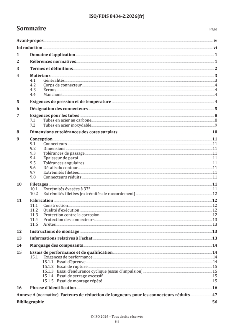
Contents Page
Foreword .iv
Introduction .vi
1 Scope . 1
2 Normative references . 1
3 Terms and definitions . 2
4 Materials . 3
4.1 General .3
4.2 Connector bodies .3
4.3 Nuts . .3
4.4 Sleeves .4
5 Pressure and temperature requirements . 4
6 Designation of connectors . 5
7 Requirements for tubes . 7
8 Across flats dimensions and tolerances . 9
9 Design .10
9.1 Connectors .10
9.2 Dimensions .10
9.3 Passage tolerances .10
9.4 Wall thickness .10
9.5 Angular tolerances .10
9.6 Contour details .10
9.7 Stud ends . .10
9.8 Reducing connectors .10
10 Screw threads .11
10.1 37° flared ends.11
10.2 Stud ends (connection ends) .11
11 Manufacture .11
11.1 Construction .11
11.2 Workmanship .11
11.3 Corrosion protection .11
11.4 Connector protection . . 12
11.5 Corners . 12
12 Assembly instructions .12
13 Procurement information .12
14 Marking of components .13
15 Performance and qualification test .13
15.1 Performance requirements . 13
15.1.1 Proof test . 13
15.1.2 Burst test . 13
15.1.3 Cyclic endurance (impulse) test .14
15.1.4 Overtightening test .14
15.1.5 Repeated assembly test .14
16 Identification statement .15
Annex A (normative) Length reduction factors for reducing connectors .46
Bibliography .54
iii
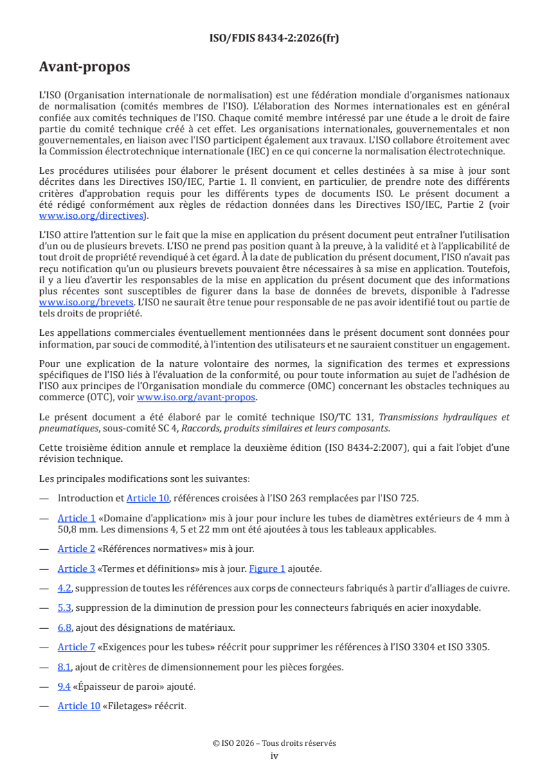
Foreword
ISO (the International Organization for Standardization) is a worldwide federation of national standards
bodies (ISO member bodies). The work of preparing International Standards is normally carried out through
ISO technical committees. Each member body interested in a subject for which a technical committee
has been established has the right to be represented on that committee. International organizations,
governmental and non-governmental, in liaison with ISO, also take part in the work. ISO collaborates closely
with the International Electrotechnical Commission (IEC) on all matters of electrotechnical standardization.
The procedures used to develop this document and those intended for its further maintenance are described
in the ISO/IEC Directives, Part 1. In particular, the different approval criteria needed for the different types
of ISO document should be noted. This document was drafted in accordance with the editorial rules of the
ISO/IEC Directives, Part 2 (see www.iso.org/directives).
ISO draws attention to the possibility that the implementation of this document may involve the use of (a)
patent(s). ISO takes no position concerning the evidence, validity or applicability of any claimed patent
rights in respect thereof. As of the date of publication of this document, ISO had not received notice of (a)
patent(s) which may be required to implement this document. However, implementers are cautioned that
this may not represent the latest information, which may be obtained from the patent database available at
www.iso.org/patents. ISO shall not be held responsible for identifying any or all such patent rights.
Any trade name used in this document is information given for the convenience of users and does not
constitute an endorsement.
For an explanation of the voluntary nature of standards, the meaning of ISO specific terms and expressions
related to conformity assessment, as well as information about ISO's adherence to the World Trade
Organization (WTO) principles in the Technical Barriers to Trade (TBT), see www.iso.org/iso/foreword.html.
This document was prepared by Technical Committee ISO/TC 131, Fluid power systems, Subcommittee SC 4,
Connectors and similar products and components.
This third edition cancels and replaces the second edition (ISO 8434-2:2007), which has been technically
revised.
The main changes are as follows:
— Introduction and Clause 10, ISO 263 cross-references replaced with ISO 725.
— Clause 1 “Scope” updated to include tubes with outside diameters from 4 mm to 50,8 mm. Sizes 4, 5, and
22 mm have been added to all applicable tables.
— Clause 2 “Normative references” updated.
— Clause 3 “Terms and definitions” updated. Figure 1 added.
— 4.2, removed all references to connector bodies made from copper alloys.
— 5.3, removed pressure derating for connectors made from stainless steel.
— 6.7, added material and letter designations.
— Clause 7 “Requirements for tubes” rewritten to remove references to ISO 3304 and ISO 3305.
— 8.1, added forging size criteria.
— 9.4 “Wall Thickness” added.
— Clause 10 “Screw Threads” rewritten.
— 11.3 “Corrosion protection” rewritten.
— Clause 12 “Assembly Instructions” rewritten.
iv
— Clause 13 “Procurement information” seal material added.
— 15.1 “Performance requirements” rewritten.
— 15.1.5 “Repeated assembly test” added, “Re-use of test samples” removed.
— Clause 16 “Identification statement” rewritten.
— All figures have been renumbered and redrawn.
— Figure 5, tolerance added to R0,5 radius.
— Figure 7 and Table 8 were added for the recommended chamfer for single flares.
a
— Table 9, footnote “ ” added.
— Figure 10, R0,26 ± 0,13 changed to R0,25 ± 0,15.
— Figure 11/Table 12, added “L ” dimension and subsequent “L” dimensions were adjusted in following
figures and tables.
— Table 13, removed Tube OD 50.
— Figure 18/Table 19 and Figure 19/Table 20, Optional dual angle seat design added.
— Figure 19/Table 20 added “L ”.
— Table A.3 factor for 9/16-18 and 16 updated to -0,4.
— Bibliography updated.
A list of all parts in the ISO 8434 series can be found on the ISO website.
Any feedback or questions on this document should be directed to the user’s national standards body. A
complete listing of these bodies can be found at www.iso.org/members.html.
v
Introduction
In fluid power systems, power is transmitted and controlled through a fluid (liquid or gas) under pressure
within an enclosed circuit. In general applications, a fluid may be conveyed under pressure.
Components may be connected through their ports by connections (connectors), tubes and hoses. Tubes are
rigid conductors; hoses are flexible conductors.
[1] [2]
This document is based on the US standard SAE J514-1 and SAE J533 . The threads for the 37° flared
connection are unified inch threads in accordance with ISO 725. The inch threads were not changed to
metric threads according to ISO 261 to allow connectors complying with this document to be used in existing
applications without requiring a change to tube or hose assemblies. Also, the thread-to-nut overtightening
and seal performance have been extensively tested; to change to metric threads would require an extensive
test program at considerable cost without providing any functional improvement. The threads are integral to
themselves, connectors of this type match only to themselves and, other than having metric threads, no value
in changing could be found. Major international companies that have used these connectors have adopted
the design without noting any problems. All wrench flats specified in this document are dimensioned to be
used with ISO standard metric wrenches.
vi
FINAL DRAFT International Standard ISO/FDIS 8434-2:2026(en)
Metallic tube connections for fluid power and general use —
Part 2:
37 degree flared connectors
1 Scope
This document specifies the general and dimensional requirements for the design and performance of
37° flared connectors that are suitable for use with ferrous and non-ferrous tubes with outside diameters
from 4 mm to 50,8 mm, inclusive. These connectors provide full-flow connections with metal-to-metal
sealings. These connectors are for use in fluid power and general applications within the limits of pressure
and temperature specified in this document.
They are intended for the connection of tubes and hose fittings to ports in accordance with ISO 6149-1,
ISO 1179-1, ISO 9974-1 and ISO 11926-1. (See ISO 12151-5 for related hose fitting specification.)
NOTE 1 For new designs in hydraulic fluid power applications, see the requirements given in 9.7. Where the
requirements of the application allow for the use of elastomeric seals, connector designs that conform to International
Standards and incorporate elastomeric sealing are preferred.
NOTE 2 For use under conditions outside the limits for pressure or temperature, or both, see 5.4.
Both metric and inch tubing can be accommodated by changing the sleeve (see Figure 9). In the past, these
connectors have been used predominantly with inch tubing. For new and future designs, the use of metric
tubing is preferred.
This document also specifies performance and qualification tests for 37° flared connectors.
2 Normative references
The following documents are referred to in the text in such a way that some or all of their content constitutes
requirements of this document. For dated references, only the edition cited applies. For undated references,
the latest edition of the referenced document (including any amendments) applies.
ISO 725, ISO inch screw threads — Basic dimensions
ISO 1127, Stainless steel tubes — Dimensions, tolerances and conventional masses per unit length
ISO 1179-3, Connections for general use and fluid power — Ports and stud ends with ISO 228-1 threads with
elastomeric or metal-to-metal sealing — Part 3: Light-duty (L series) stud ends with sealing by O-ring with
retaining ring (types G and H)
ISO 4759-1, Tolerances for fasteners — Part 1: Bolts, screws, studs and nuts — Product grades A, B and C
ISO 5598, Fluid power systems and components — Vocabulary
ISO 6149-3, Connections for hydraulic fluid power and general use — Ports and stud ends with ISO 261 metric
threads and O-ring sealing — Part 3: Dimensions, design, test methods and requirements for light-duty (L series)
stud ends
ISO 9227, Corrosion tests in artificial atmospheres — Salt spray tests
ISO 9974-2, Connections for general use and fluid power — Ports and stud ends with ISO 261 threads with
elastomeric or metal-to-metal sealing — Part 2: Stud ends with elastomeric sealing (type E)
ISO 11926-3, Connections for general use and fluid power — Ports and stud ends with ISO 725 threads and
O-ring sealing — Part 3: Light-duty (L series) stud ends
ISO 19879, Metallic tube connections for fluid power and general use — Test methods for hydraulic fluid power
connections
ISO 21920-1, Geometrical product specifications (GPS) — Surface texture: Profile — Part 1: Indication of surface
texture
3 Terms and definitions
For the purposes of this document, the terms and definitions given in ISO 5598 and the following apply.
ISO and IEC maintain terminology databases for use in standardization at the following addresses:
— ISO Online browsing platform: available at https:// www .iso .org/ obp
— IEC Electropedia: available at https:// www .electropedia .org/
3.1
adjustable stud end
stud end connector that allows for connector orientation through final tightening of the locknut to complete
the connection
Note 1 to entry: This type of stud end is typically used on shaped connectors (e.g. tees, crosses and elbows).
3.2
non-adjustable stud end
stud end connector that does not require specific orientation before final tightening of the connection
because it is only used on straight connectors
3.3
run
two principal, axially aligned outlets of a tee connector or cross connector
Key
1 run
2 branch
Figure 1 — Run and branch illustration
3.4
branch
side outlet(s) of a tee connector or cross connector
3.5
chamfer
removal of a conical portion at the entrance of a thread to assist assembly and prevent damage to the start
of the thread
3.6
assembly torque
torque required to achieve a satisfactory final connection
3.7
qualification test torque
torque used to verify conformity of the connector to the requirements of this document
3.8
overtightening
torque that the nut withstands without deformation that renders it unusable
3.9
jump size connector
connector with dis-similar end connections, for example, –6 male flare with a –12 stud end
4 Materials
4.1 General
Figure 2 shows the cross-section and components of a typical 37° flared connector.
Key
1 straight stud connector body
2 tube nut
3 tube
4 sleeve
5 O-ring
a
Stud end in accordance with ISO 1179-3, ISO 6149-3, ISO 9974-2 or ISO 11926-3.
Figure 2 — Cross-section of typical 37° flared connection
4.2 Connector bodies
Bodies shall be manufactured from carbon steel or stainless steel, which will provide the minimum
requirements for the pressure and temperature ratings specified in Clause 5 when tested in accordance
with Clause 15. They shall have characteristics that make them suitable for use with the fluid to be conveyed
and to provide an effective joint.
4.3 Nuts
Nuts to be used with carbon steel bodies shall be made of carbon steel and those for use with stainless steel
bodies shall be made of stainless steel unless otherwise specified.
4.4 Sleeves
Sleeves shall be manufactured from a material similar to the bodies.
5 Pressure and temperature requirements
5.1 The working pressure of the connector shall be the lower of the working pressure of the 37° flared
connector connection given in Table 1 and the working pressure of the respective stud end.
5.2 Flared connectors in accordance with this document made of carbon steel shall meet or exceed without
leakage the requirements to the working pressures given in Table 1 when used at temperatures from −40 °C
to +120 °C with petroleum base hydraulic fluids.
5.3 Connectors made of stainless steel complying with this document shall be suitable for use at the
working pressures given in Table 1 when used at temperatures from −60 °C to +50 °C.
5.4 For applications under conditions outside the limits for pressure or temperature, or both given in
Table 1 and in 5.2 and 5.3, the manufacturer shall be consulted.
5.5 Connectors conforming to this document shall be tested in accordance with Clause 15 to ensure that
they meet or exceed the pressure requirements given in Table 1.
5.6 The pressure and temperature requirements given in Table 1 and in 5.2 and 5.3 are for tube
connections and connector bodies only. For port and stud end pressure and temperature ratings, the values
in the respective port and stud end standards shall apply.
5.7 To achieve these maximum working pressures with a 4:1 design factor, the maximum tube wall
thicknesses shown in Table 1 are sufficient. See ISO 10763 to confirm the necessary tube wall thickness for a
specific working pressure.
Table 1 — Working pressures for 37° flared connections
Maximum wall thickness of
b
Tube outside diameter (OD) Maximum working pressure
a
tube for flaring
Metric Inch Metric tube Inch tube Carbon steel and stainless steel
c
mm in mm mm MPa (bar)
4 1/8 1 0,89 35 (350)
5 3/16 1 0,89 35 (350)
6 1/4 1,5 1,65 35 (350)
8 5/16 1,5 1,65 35 (350)
10 3/8 1,5 1,65 35 (350)
12 1/2 2 2,1 31 (310)
16 5/8 2,5 2,41 24 (240)
20 3/4 3 2,77 24 (240)
22 7/8 3 2,77 21 (210)
25 1 3 3,05 21 (210)
a
Maximum wall thickness that can be flared, due to connector design.
b
For working pressure applications higher than those given in this table, the manufacturer shall be consulted.
c 5 2 5
1 bar = 10 N/m = 10 Pa = 0,1 MPa.
TTabablele 1 1 ((ccoonnttiinnueuedd))
Maximum wall thickness of
b
Tube outside diameter (OD) Maximum working pressure
a
tube for flaring
Metric Inch Metric tube Inch tube Carbon steel and stainless steel
30 and 32 1 1/4 3 3,05 17 (170)
38 1 1/2 3 3,05 14 (140)
50 2 3,5 3,4 10,5 (105)
a
Maximum wall thickness that can be flared, due to connector design.
b
For working pressure applications higher than those given in this table, the manufacturer shall be consulted.
c 5 2 5
1 bar = 10 N/m = 10 Pa = 0,1 MPa.
6 Designation of connectors
6.1 Connectors shall be designated by an alphanumeric code to facilitate ordering. They shall be
designated by the word “Connector”, followed by ISO 8434-2, followed by a space, then the connector style
letter symbols (see 6.2), followed by a hyphen, then, for the ends, the outside diameter of the tube with
which they are to be connected, each separated by a multiplication symbol, ×. There shall be no space on
either side of the multiplication symbol. For stud ends (connector ends), the thread designation of the stud
end shall be added followed by a hyphen, and followed by connector material symbol.
6.2 The letter symbol designation of the connector style shall have three parts: a) the connection end type
immediately followed by b) the shape of the connector and c) by the indication that a complete connector is
being ordered. The letters A and B shall be used to distinguish different styles, where such options exist.
6.3 Tube ends are assumed to be external connections and thus do not need to be included in the
connection type code. However, if another type of connection is involved, it shall be designated.
6.4 Reducing connectors and elbows shall be designated by specifying the larger tube end first.
6.5 Stud connectors shall be designated by specifying the tube end first, then the thread size for the stud
end.
6.6 For tee connectors, the order of designation of the connection ends shall be from the larger to the
smaller tube end on the run, followed by the branch end.
6.7 For cross connectors, the order of designation of the connection ends shall be from left to right,
followed by from top to bottom, with the larger ends on the left and at the top.
6.8 The following letter symbols shall be used:
Connection end type Letter
Bulkhead BH
Swivel SW
Reducer RD
Stud SD
Shape Letter
Straight S
90° elbow E
45° elbow E45
Tee T
Run tee RT
Branch tee BT
Cross K
Long L
Component type Letter
Nut N
Sleeve SL
Locknut LN
Plug PL
Cap CP
Nipple NP
Metric M
Inch I
Completeness indication Letter
Complete connector C
Stud end sealing types Letter
Metal-to-metal sealing B
Elastomeric sealing E
O-ring sealing F
Material Letter
Steel S
Stainless steel SS
6.9 Examples of 37° flared connectors and designations are given in Figures 3 and 4.
EXAMPLE A straight stud connector (SDS), including O-ring without sleeve and nut, for use with 12 mm OD tubing
with an 3/4-16 UNF stud end in accordance with ISO 11926-3, made with steel, is designated for ordering as follows:
ConnectorISO 8434-2SDS-12×3/4-16F-S
Figure 3 — Straight stud connector (SDS) with stud end in accordance with ISO 11926-3
EXAMPLE A complete straight stud connector (SDSC), including O-ring with sleeve and nut, for use with 12 mm
OD tubing with an M16 × 1,5 stud end in accordance with ISO 6149-3, made with stainless steel, is designated for
ordering as follows:
ConnectorISO 8434-2SDSC-12×M16F-SS
Figure 4 — Straight stud connector, complete (SDSC) with stud end in accordance with ISO 6149-3
(sealing type F)
7 Requirements for tubes
7.1 The connectors shall be suitable for use with tubes with dimensions as given in Table 2 and Table 3.
The outside diameter tolerances include ovality. Tubes shall be free of scratches, damage, and imperfections
that would be considered detrimental to the function of the tubing.
7.2 Carbon steel tubes
7.2.1 Carbon steel tubes shall be seamless, cold drawn, and normalized. The steel tubes shall be weldable
and the content of carbon in its chemical composition shall not exceed 0,22 %.
7.2.2 Mechanical properties in normalized condition at room temperature shall be as follows.
Yield strength: R : 225 MPa
eh min.
Tensile strength: R : 340 to 630 MPa
m
Elongation after fracture: A : 25 % for R < 480 MPa
min. m
22 % for R 480 to 630 MPa
m
7.2.3 The following surface protections are recommended.
Tubes for welding purpose: phosphated or unplated.
Tubes for flaring purpose: zinc plated, passivated, phosphated, or unplated.
Plating applied should not exceed the tube outside diameter tolerance specified in Table 2 and Table 3 and
shall be compatible with the flaring process such that flare quality and cleanliness are not impacted.
7.2.4 Inspection and testing documentation shall be provided which contain at least the following
information:
— chemical analysis;
— tensile testing (see ISO 6892-1);
— tube forming drift expanding testing (see ISO 8493);
— dimensional inspection;
— non-destructive testing for the verification of hydraulic leaktightness (see ISO 10893-1);
— non-destructive testing for the detection of longitudinal imperfections (see ISO 10893-10);
— plating information.
7.3 Stainless steel tubes
7.3.1 Stainless steel tubes shall comply with ISO 1127.
7.3.2 Stainless steel tubes shall be cold-drawn, solution annealed, and scale-free. Tubes made of stainless
steel shall be suitable for welding.
7.3.3 Mechanical properties after heat treatment at room temperature shall be as follows:
Yield strength: R : 245 MPa
p0,2 min.
Tensile strength: R : 500 to 730 MPa
m
Elongation after fracture: A : 35 %
min.
Reference hardness: max. 90 HRB in accordance with ISO 6508-1
7.3.4 Inspection and testing documentation shall be provided which contain at least the following
information:
— chemical analysis;
— tensile testing (see ISO 6892-1);
— tube forming drift expanding testing (see ISO 8493) or Ring-expanding test (see ISO 8495);
— resistance to intergranular corrosion (see ISO 3651-2);
— dimensional inspection;
— non-destructive testing for the verification of hydraulic leaktightness (see ISO 10893-1);
— non-destructive testing for the detection of longitudinal imperfections (see ISO 10893-10).
Table 2 — Metric tube sizes
Tube OD Limits of OD
mm mm
min. max.
4 3,9 4,1
5 4,9 5,1
6 5,9 6,1
8 7,9 8,1
10 9,9 10,1
12 11,9 12,1
16 15,9 16,1
20 19,9 20,1
22 21,9 22,1
25 24,9 25,1
30 29,85 30,15
32 31,85 32,15
38 37,85 38,15
50 49,8 50,2
Metric tubing shall be preferred.
Table 3 — Inch tube sizes
Tube OD Limits of OD
mm
a
in mm
min. max.
1/8 3,18 3,08 3,28
3/16 4,76 4,66 4,86
1/4 6,35 6,25 6,45
5/16 7,94 7,84 8,04
3/8 9,52 9,42 9,62
1/2 12,7 12,6 12,8
5/8 15,88 15,78 15,98
3/4 19,05 18,95 19,15
7/8 22,22 22,12 22,32
1 25,4 25,3 25,5
1 1/4 31,75 31,6 31,9
1 1/2 38,1 37,95 38,25
2 50,8 50,6 51
a
Equivalent dimension in millimetres.
8 Across flats dimensions and tolerances
8.1 The dimensions across flats of elbow, tee and cross connectors shall be as shown in the respective
tables with minus tolerance only. For sizes up to and including 24 mm, tolerances for across flats dimensions
0 0
for forgings shall be mm, and for sizes larger than 24 mm, they shall be mm. The basic forging size
−0,8 −1,0
may be increased up to the maximum size shown for barstock, but the size selected shall be a metric
across-flat size with minus tolerance only.
8.2 Hex tolerances shall be in accordance with ISO 4759-1, product grade C. Minimum across corner hex
dimensions are 1,092 times the nominal width across flats. The minimum side flat is 0,43 times the nominal
width across flats, unless otherwise specified or shown, hex corners shall be chamfered 15° to 30° to a
diameter equal to the width across flats, with a tolerance of mm.
−0,4
9 Design
9.1 Connectors
The connectors shall conform to the requirements given in Figures 5 to 19 and Tables 6 to 20. They shall be
designed so that resistance to flow is reduced to a minimum.
9.2 Dimensions
Dimensions specified apply to finished parts, including any plating or other treatments. The tolerance
value for all dimensions not otherwise limited shall be ±0,4 mm. The sealing seats of connectors shall be
concentric, with straight thread pitch diameters within 0,25 mm full indicator reading (FIR).
9.3 Passage tolerances
Where passages in straight connectors are machined from opposite ends, the offset at the meeting point
shall not exceed 0,4 mm. No cross-sectional area at a junction of passages shall be less than that of the
smallest passage.
9.4 Wall thickness
Unless otherwise designated, the wall thickness at any point on the connectors shall not be less than the
thickness established by the specified dimensions, tolerances, and eccentricities for inner and outer surfaces.
9.5 Angular tolerances
Angular tolerance on axes of end on elbows, tees, and crosses shall be ±2,5° for tube sizes up to and including
10 mm and ±1,5° for all larger sizes.
9.6 Contour details
Details of contour shall be chosen by the manufacturer, provided the dimensions given in Tables 6 to 20 are
maintained. Wrench flats on elbows, tees, and crosses shall conform to the dimensions given in the relevant
tables. Abrupt reduction of a section shall be avoided. Junctions of small external sections and adjoining
sections that are relatively heavy shall be blended by means of ample fillets.
9.7 Stud ends
The dimensions for the stud ends shall conform to those given in ISO 6149-3. Stud ends in accordance with
ISO 1179-3, ISO 9974-2 and ISO 11926-3 shall not be used for new designs in fluid power applications.
9.8 Reducing connectors
Dimension of reducing connectors shall be in accordance with Annex A.
10 Screw threads
10.1 37° flared ends
The screw threads on the tube flared ends of the connectors shall be ISO inch screw threads in accordance
with ISO 725. Straight threads shall be class 2A or 2B, except external threads which are plated or coated
may exceed 2A diameters but shall not exceed maximum of 3A diameters. Internal threads of all classes
shall be within specified limits after plating or coating.
When external threads are produced by thread rolling and the body is not undercut, the unthreaded area
adjacent to the shoulder may be reduced to the minimum pitch diameter.
External threads shall be chamfered and internal threads shall be countersunk as specified.
10.2 Stud ends (connection ends)
The screw threads for stud ends of connectors shall be in accordance with the applicable defined stud end
standard. The dimensions of the stud end connectors shall comply with the requirements given in this
document.
11 Manufacture
11.1 Construction
Unless otherwise specified, connectors shall be made from carbon steel.
Stainless steel connectors shall be made from the material specified by the user and shall be passivated.
Carbon steel and stainless steel connectors fabricated from multiple components must be bonded together
with materials having a melting point of not less than 1 000 °C (1 832 °F).
11.2 Workmanship
Workmanship shall conform to the best commercial practice to produce high-quality connectors. Connectors
shall be free from visual contaminants, all hanging burrs, loose scale and slivers which might be dislodged
in use and any other defects that might affect the function of the parts. All machined surfaces shall have
a surface roughness value of MRR Ramax 6,3 specified in accordance with ISO 21920-1, except where
otherwise specified.
11.3 Corrosion protection
The external surfaces and threads of all carbon steel parts shall be plated or coated with a suitable material
that passes a salt spray test in accordance with ISO 9227. The following requirements shall apply:
a) No appearance of corrosion products of the protective coating before 96 h.
b) No appearance of corrosion products of the base metal before 144 h.
The following exceptions shall apply:
a) All internal fluid passages.
b) Edges such as hex points, serrations and crests of threads where there may be mechanical deformation
of the plating or coating typical of mass-produced parts or shipping effects.
c) Areas where there is mechanical deformation of the plating or coating caused by crimping, flaring
bending and other post-plate metal forming operations.
d) Areas where the parts are suspended or affixed in the test chamber where condensate can accumulate.
Parts manufactured to this specification shall not be cadmium plated and shall not use hexavalent chromate
coatings. Internal fluid passages shall be protected from corrosion during storage and shipping. Changes in
plating or coating shall be re-qualified to ensure assembly torque is not affected.
11.4 Connector protection
By a method agreed between manufacturer and user, the face of the connectors and threads (both internal
and external) shall be protected by the manufacturer from nicks and scratches that would be detrimental
to the function of the connector. Passages shall be securely covered to prevent the entrance of dirt or other
contaminants. Nuts and sleeves that are furnished separately from the connector shall be protected from
rust, but do not require capping.
11.5 Corners
Unless otherwise noted, all sharp corners shall be broken to 0,15 mm maximum.
12 Assembly instructions
The assembly of the connectors with the connecting tubes shall be carried out without external loads.
Upon request the manufacturer shall provide assembly instructions for the use of the connectors. These
instructions should include the following information:
— details relating to material and quality of suitable tubes;
— details concerning the preparation of the selected tube;
— instructions regarding the assembly of the connector, such as number of wrenching turns or assembly
torque;
— recommendations regarding the tools to be used for assembly;
— torque values listed in Table 5 are for controlled testing to establish compliance to the performance
requirements set forth in Table 4. Recommended assembly torques by manufacturers may vary from
Table 5;
— smaller sizes (–2 through –8) of 37° flare connectors are less tolerant to overtightening than the larger
sizes. Overtightening in these sizes causes deformation of 37° cone of the male end. Excessive deformation
of the cone results in loss of clamping force and, hence, loss of seal. It can also reduce flow area.
13 Procurement information
The following information should be supplied by the user when making an inquiry or placing an order. Refer
to the designation of connectors in in Clause 6 for additional information:
— description of connector;
— material of connector;
— material and size of tube;
— fluid to be conveyed;
— working pressure;
— fluid working temperature range;
— ambient temperature range;
— seal material.
14 Marking of components
Connector bodies and nuts shall be permanently marked with the manufacturer's name, trademark or code
identifier, unless otherwise agreed upon by the user and manufacturer. Nuts to be used with connectors
used with 30 mm and 32 mm tubes shall be marked with the relevant tube outside diameter.
15 Performance and qualification test
15.1 Performance requirements
The following outlines the performance test requirements for standard 37° flared connectors. Connectors,
swivel nuts, and sleeves shall be tested in accordance with ISO 19879, unless otherwise specified. In addition
to the test requirements and procedures specified, all components must be able to pass the performance
requirements in the as-shipped condition (e.g. annealed components, plating, coatings, rust preventative).
Working pressures for connectors, tube connections, cap nuts, and hose fittings shall be as listed in Table 4
or as specified in respective clause. Proof pressures shall be twice the working pressures and minimum
burst pressures shall be four times the working pressures.
15.1.1 Proof test
For each size, nine test assemblies in accordance with ISO 19879 shall be subjected to the proof test procedure
specified in ISO 19879, prior to burst and cyclic endurance tests. They shall not leak at the respective proof
pressures given in Table 4.
Table 4 — Test pressures for steel and stainless steel 37° flared connections
Maximum work-
Tube OD Test pressures
a
ing pressure
Metric Inch Proof Burst Cyclic endurance
b
Mm in MPa (bar) MPa (bar) MPa (bar) MPa (bar)
4 1/8 35 (350) 70 (700) 140 (1 400) 46,6 (466)
5 3/16 35 (350) 70 (700) 140 (1 400) 46,6 (466)
6 1/4 35 (350) 70 (700) 140 (1 400) 46,6 (466)
8 5/16 35 (350) 70 (700) 140 (1 400) 46,6 (466)
10 3/8 35 (350) 70 (700) 140 (1 400) 46,6 (466)
12 ½ 31 (310) 62 (620) 124 (1 240) 41,2 (412)
16 5/8 24 (240) 48 (480) 96 (960) 31,9 (319)
20 ¾ 24 (240) 48 (480) 96 (960) 31,9 (319)
22 7/8 21 (210) 42 (420) 84 (840) 27,9 (279)
25 1 21
...
ISO/TC 131/SC 04 4
Secretariat: ANSI
Date: 2026-06-30xx
Metallic tube connections for fluid power and general use —
Part 2:
37° Flared degree flared connectors
Raccordements de tubes métalliques pour transmissions hydrauliques et pneumatiques et applications
générales —
Partie 2: Connecteurs évasés à 37 degrés
FDIS stage
All rights reserved. Unless otherwise specified, or required in the context of its implementation, no part of this publication
may be reproduced or utilized otherwise in any form or by any means, electronic or mechanical, including photocopying,
or posting on the internet or an intranet, without prior written permission. Permission can be requested from either ISO
at the address below or ISO’s member body in the country of the requester.
ISO copyright office
CP 401 • Ch. de Blandonnet 8
CH-1214 Vernier, Geneva
Phone: + 41 22 749 01 11
EmailE-mail: copyright@iso.org
Website: www.iso.org
Published in Switzerland
ii
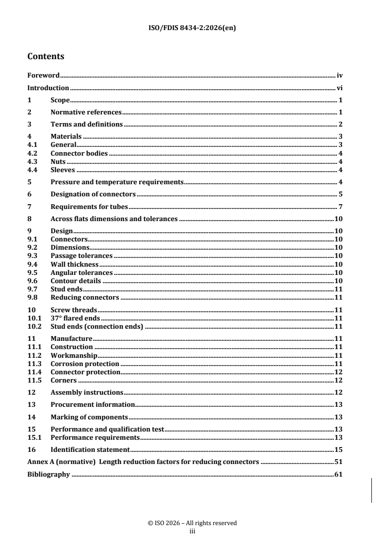
Contents
Foreword . iv
Introduction . vi
1 Scope . 1
2 Normative references . 1
3 Terms and definitions . 2
4 Materials . 3
4.1 General . 3
4.2 Connector bodies . 4
4.3 Nuts . 4
4.4 Sleeves . 4
5 Pressure and temperature requirements . 4
6 Designation of connectors . 5
7 Requirements for tubes . 7
8 Across flats dimensions and tolerances . 10
9 Design . 10
9.1 Connectors . 10
9.2 Dimensions . 10
9.3 Passage tolerances . 10
9.4 Wall thickness . 10
9.5 Angular tolerances . 10
9.6 Contour details . 10
9.7 Stud ends . 11
9.8 Reducing connectors . 11
10 Screw threads . 11
10.1 37° flared ends . 11
10.2 Stud ends (connection ends) . 11
11 Manufacture . 11
11.1 Construction . 11
11.2 Workmanship . 11
11.3 Corrosion protection . 11
11.4 Connector protection. 12
11.5 Corners . 12
12 Assembly instructions . 12
13 Procurement information . 13
14 Marking of components . 13
15 Performance and qualification test . 13
15.1 Performance requirements . 13
16 Identification statement . 15
Annex A (normative) Length reduction factors for reducing connectors . 51
Bibliography . 61
iii
Foreword
ISO (the International Organization for Standardization) is a worldwide federation of national standards
bodies (ISO member bodies). The work of preparing International Standards is normally carried out through
ISO technical committees. Each member body interested in a subject for which a technical committee has been
established has the right to be represented on that committee. International organizations, governmental and
non-governmental, in liaison with ISO, also take part in the work. ISO collaborates closely with the
International Electrotechnical Commission (IEC) on all matters of electrotechnical standardization.
The procedures used to develop this document and those intended for its further maintenance are described
in the ISO/IEC Directives, Part 1. In particular, the different approval criteria needed for the different types of
ISO document should be noted. This document was drafted in accordance with the editorial rules of the
ISO/IEC Directives, Part 2 (see www.iso.org/directives).
ISO draws attention to the possibility that the implementation of this document may involve the use of (a)
patent(s). ISO takes no position concerning the evidence, validity or applicability of any claimed patent rights
in respect thereof. As of the date of publication of this document, ISO had not received notice of (a) patent(s)
which may be required to implement this document. However, implementers are cautioned that this may not
represent the latest information, which may be obtained from the patent database available at
www.iso.org/patents. ISO shall not be held responsible for identifying any or all such patent rights.
Any trade name used in this document is information given for the convenience of users and does not
constitute an endorsement.
For an explanation of the voluntary nature of standards, the meaning of ISO specific terms and expressions
related to conformity assessment, as well as information about ISO's adherence to the World Trade
Organization (WTO) principles in the Technical Barriers to Trade (TBT), see www.iso.org/iso/foreword.html.
This document was prepared by Technical Committee ISO/TC 131, Fluid power systems, Subcommittee SC 4,
Connectors and similar products and components.
This third edition cancels and replaces the second edition (ISO 8434-2:2007), which has been technically
revised.
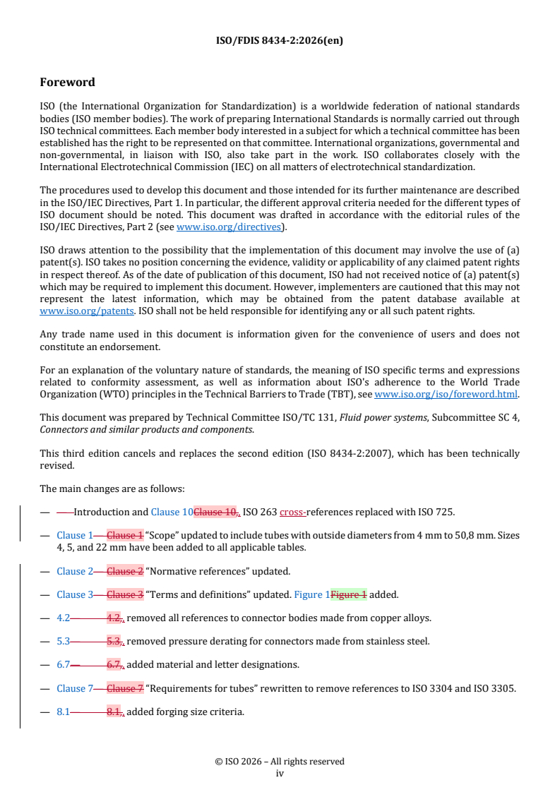
The main changes are as follows:
— — Introduction and Clause 10Clause 10,, ISO 263 cross-references replaced with ISO 725.
— Clause 1— Clause 1 “Scope” updated to include tubes with outside diameters from 4 mm to 50,8 mm. Sizes
4, 5, and 22 mm have been added to all applicable tables.
— Clause 2— Clause 2 “Normative references” updated.
— Clause 3— Clause 3 “Terms and definitions” updated. Figure 1Figure 1 added.
— 4.2— 4.2,, removed all references to connector bodies made from copper alloys.
— 5.3— 5.3,, removed pressure derating for connectors made from stainless steel.
— 6.7— 6.7,, added material and letter designations.
— Clause 7— Clause 7 “Requirements for tubes” rewritten to remove references to ISO 3304 and ISO 3305.
— 8.1— 8.1,, added forging size criteria.
iv
— 9.4— 9.4 “Wall Thickness” added.
— Clause 10— Clause 10 “Screw Threads” rewritten.
— 11.3— 11.3 “Corrosion protection” rewritten.
— Clause 12— Clause 12 “Assembly Instructions” rewritten.
— Clause 13— Clause 13 “Procurement information” seal material added.
— 15.1— 15.1 “Performance requirements” rewritten.
— 15.1.5—
— — Clause 15.1.5 “Repeated assembly test” added, “Re-use of test samples” removed.
— Clause 16— Clause 16 “Identification statement” rewritten.
— — All figures have been renumbered and redrawn.
— Figure 5— Figure 5,, tolerance added to R0,5 radius.
— Figure 7— Figure 7 and Table 8Table 8 were added for the recommended chamfer for single flares.
a
— Table 9— Table 9,, footnote “ ” added.
— Figure 10— Figure 10,, R0,26 ± 0,13 changed to R0,25 ± 0,15.
— Figure 11/Table 12— Figure 11/Table 12,, added “L ” dimension and subsequent “L” dimensions
were adjusted in following figures and tables.
— Table 13— Table 13,, removed Tube OD 50.
— Figure 18— Figure 18/Table 19/Table 19 and Figure 19/Table 20Figure 19/Table 20,,
Optional dual angle seat design added.
— Figure 19— Figure 19/Table 20/Table 20 added “L ”.
— Table A.3— Table A.3 factor for 9/16-18 and 16 updated to -0,4.
— — Bibliography updated.
A list of all parts in the ISO 8434 series can be found on the ISO website.
Any feedback or questions on this document should be directed to the user’s national standards body. A
complete listing of these bodies can be found at www.iso.org/members.html.
v
Introduction
In fluid power systems, power is transmitted and controlled through a fluid (liquid or gas) under pressure
within an enclosed circuit. In general applications, a fluid may be conveyed under pressure.
Components may be connected through their ports by connections (connectors), tubes and hoses. Tubes are
rigid conductors; hoses are flexible conductors.
[1][1] [2] [3]
This document is based on the US standard ANSI/SAE J514-1 and SAE J533 . . The threads for the 37°
flared connection are unified inch threads in accordance with ISO 725. The inch threads were not changed to
metric threads according to ISO 261 to allow connectors complying with this document to be used in existing
applications without requiring a change to tube or hose assemblies. Also, the thread-to-nut overtightening and
seal performance have been extensively tested; to change to metric threads would require an extensive test
program at considerable cost without providing any functional improvement. The threads are integral to
themselves, connectors of this type match only to themselves and, other than having metric threads, no value
in changing could be found. Major international companies that have used these connectors have adopted the
design without noting any problems. All wrench flats specified in this document are dimensioned to be used
with ISO standard metric wrenches.
vi
Metallic tube connections for fluid power and general use — Part 2:
37° flared connectors
Part 2:
37 degree flared connectors
1 Scope
This document specifies the general and dimensional requirements for the design and performance of
37° flared connectors that are suitable for use with ferrous and non-ferrous tubes with outside diameters from
4 mm to 50,8 mm, inclusive. These connectors provide full-flow connections with metal-to-metal sealings.
These connectors are for use in fluid power and general applications within the limits of pressure and
temperature specified in this document.
They are intended for the connection of tubes and hose fittings to ports in accordance with ISO 6149--1,
ISO 1179--1, ISO 9974--1 and ISO 11926--1. (See ISO 12151--5 for related hose fitting specification.)
NOTE 1 For new designs in hydraulic fluid power applications, see the requirements given in 9.79.7. Where the
requirements of the application allow for the use of elastomeric seals, connector designs that conform to International
Standards and incorporate elastomeric sealing are preferred.
NOTE 2 For use under conditions outside the limits for pressure or temperature, or both, see 5.45.4.
Both metric and inch tubing can be accommodated by changing the sleeve (see Figure 9Figure 9).). In the past,
these connectors have been used predominantly with inch tubing. For new and future designs, the use of
metric tubing is preferred.
This document also specifies performance and qualification tests for 37° flared connectors.
2 Normative references
The following documents are referred to in the text in such a way that some or all of their content constitutes
requirements of this document. For dated references, only the edition cited applies. For undated references,
the latest edition of the referenced document (including any amendments) applies.
ISO 725, ISO inch screw threads — Basic dimensions
ISO 1127, Stainless steel tubes — Dimensions, tolerances and conventional masses per unit length
ISO 1179--3, Connections for general use and fluid power — Ports and stud ends with ISO 228-1 threads with
elastomeric or metal-to-metal sealing — Part 3: Light-duty (L series) stud ends with sealing by O-ring with
retaining ring (types G and H))
ISO 4759--1, Tolerances for fasteners — Part 1: Bolts, screws, studs and nuts — Product grades A, B and C
ISO 5598, Fluid power systems and components — Vocabulary
ISO 6149--3, Connections for hydraulic fluid power and general use — Ports and stud ends with ISO 261 metric
threads and O-ring sealing — Part 3: Dimensions, design, test methods and requirements for light-duty (L series)
stud ends
ISO 9227, Corrosion tests in artificial atmospheres — Salt spray tests
ISO 9974--2, Connections for general use and fluid power — Ports and stud ends with ISO 261 threads with
elastomeric or metal-to-metal sealing — Part 2: Stud ends with elastomeric sealing (type E))
ISO 11926--3, Connections for general use and fluid power — Ports and stud ends with ISO 725 threads and O-
ring sealing — Part 3: Light-duty (L series) stud ends
ISO 19879, Metallic tube connections for fluid power and general use — Test methods for hydraulic fluid power
connections
ISO 21920-1, Geometrical product specifications (GPS) — Surface texture: Profile — Part 1: Indication of surface
texture
3 Terms and definitions
For the purposes of this document, the terms and definitions given in ISO 5598 and the following apply.
ISO and IEC maintain terminology databases for use in standardization at the following addresses:
— — ISO Online browsing platform: available at https://www.iso.org/obp
— — IEC Electropedia: available at https://www.electropedia.org/
3.1 3.1
adjustable stud end
stud end connector that allows for connector orientation through final tightening of the locknut to complete
the connection
Note 1 to entry: This type of stud end is typically used on shaped connectors (e.g. tees, crosses and elbows).
3.2 3.2
non-adjustable stud end
stud end connector that does not require specific orientation before final tightening of the connection because
it is only used on straight connectors
3.3 3.3
run
two principal, axially aligned outlets of a tee connector or cross connector
8434-2_ed3fig1.EPS
Key
1 run
2 branch
Figure 1 — Run and branch illustration
3.4 3.4
branch
side outlet(s) of a tee connector or cross connector
3.5 3.5
chamfer
removal of a conical portion at the entrance of a thread to assist assembly and prevent damage to the start of
the thread
3.6 3.6
assembly torque
torque required to achieve a satisfactory final connection
3.7 3.7
qualification test torque
torque used to verify conformity of the connector to the requirements of this document
3.8 3.8
overtightening
torque that the nut withstands without deformation that renders it unusable
3.9 3.9
jump size connector
connectorsconnector with dis-similar end connections, for example, -–6 male flare with a -–12 stud end
4 Materials
4.1 General
Figure 2Figure 2 shows the cross-section and components of a typical 37° flared connector.
8434-2_ed3fig2.EPS
Key
1 straight stud connector body
2 tube nut
3 tube
4 sleeve
5 O-ring
a
Stud end in accordance with ISO 1179-3, ISO 6149-3, ISO 9974-2 or ISO 11926-3.
Figure 2 — Cross-section of typical 37° flared connection
4.2 Connector bodies
Bodies shall be manufactured from carbon steel or stainless steel, which will provide the minimum
requirements for the pressure and temperature ratings specified in Clause 5Clause 5 when tested in
accordance with Clause 15Clause 15. They shall have characteristics that make them suitable for use with the
fluid to be conveyed and to provide an effective joint.
4.3 Nuts
Nuts to be used with carbon steel bodies shall be made of carbon steel and those for use with stainless steel
bodies shall be made of stainless steel unless otherwise specified.
4.4 Sleeves
Sleeves shall be manufactured from a material similar to the bodies.
5 Pressure and temperature requirements
5.1 5.1 The working pressure of the connector shall be the lower of the working pressure of the
37° flared connector connection given in Table 1Table 1 and the working pressure of the respective stud
end.
5.2 5.2 Flared connectors in accordance with this document made of carbon steel shall meet or exceed
without leakage the requirements to the working pressures given in Table 1Table 1 when used at
temperatures from −40 °C to +120 °C with petroleum base hydraulic fluids.
5.3 5.3 Connectors made of stainless steel complying with this document shall be suitable for use at
the working pressures given in Table 1Table 1 when used at temperatures from −60 °C to +50 °C.
5.4 5.4 For applications under conditions outside the limits for pressure or temperature, or both given
in Table 1Table 1 and in 5.25.2 and 5.35.3,, the manufacturer shall be consulted.
5.5 5.5 Connectors conforming to this document shall be tested in accordance with
Clause 15Clause 15 to ensure that they meet or exceed the pressure requirements given in
Table 1Table 1.
5.6 5.6 The pressure and temperature requirements given in Table 1Table 1 and in 5.25.2 and
5.35.3 are for tube connections and connector bodies only. For port and stud end pressure and temperature
ratings, the values in the respective port and stud end standards shall apply.
5.7 5.7 To achieve these maximum working pressures with a 4:1 design factor, the maximum tube wall
thicknesses shown in Table 1Table 1 are sufficient. See ISO 10763 to confirm the necessary tube wall
thickness for a specific working pressure.
Table 1 — Working pressures for 37° flared connections
Tube outside diameter Maximum wall thickness of Maximum working
a b
(OD) tube for flaring pressure
Carbon steel and stainless
Metric Inch Metric tube Inch tube
steel
c
mm in mm mm MPa (bar)
4 1/8 1 0,89 35 (350)
5 3/16 1 0,89 35 (350)
6 1/4 1,5 1,65 35 (350)
Tube outside diameter Maximum wall thickness of Maximum working
a b
(OD) tube for flaring pressure
Carbon steel and stainless
Metric Inch Metric tube Inch tube
steel
8 5/16 1,5 1,65 35 (350)
10 3/8 1,5 1,65 35 (350)
12 1/2 2 2,1 31 (310)
16 5/8 2,5 2,41 24 (240)
20 3/4 3 2,77 24 (240)
22 7/8 3 2,77 21 (210)
25 1 3 3,05 21 (210)
30 and 32 1 1/4 3 3,05 17 (170)
38 1 1/2 3 3,05 14 (140)
50 2 3,5 3,4 10,5 (105)
a Maximum wall thickness that can be flared, due to connector design.
b For working pressure applications higher than those given in this table, the manufacturer shall be consulted.
5 2 5
c 1 bar = 10 N/m = 10 Pa = 0,1 MPa.
6 Designation of connectors
6.1 6.1 Connectors shall be designated by an alphanumeric code to facilitate ordering. They shall be
designated by the word “Connector”, followed by ISO 8434-2, followed by a space, then the connector style
letter symbols (see 6.26.2),), followed by a hyphen, then, for the ends, the outside diameter of the tube with
which they are to be connected, each separated by a multiplication symbol, ×. There shall be no space on either
side of the multiplication symbol. For stud ends (connector ends), the thread designation of the stud end shall
be added followed by a hyphen, and followed by connector material symbol.
6.2 6.2 The letter symbol designation of the connector style shall have three parts: a) the connection
end type immediately followed by b) the shape of the connector and c) by the indication that a complete
connector is being ordered. The letters A and B shall be used to distinguish different styles, where such options
exist.
6.3 6.3 Tube ends are assumed to be external connections and thus do not need to be included in the
connection type code. However, if another type of connection is involved, it shall be designated.
6.4 6.4 Reducing connectors and elbows shall be designated by specifying the larger tube end first.
6.5 6.5 Stud connectors shall be designated by specifying the tube end first, then the thread size for
the stud end.
6.6 6.6 For tee connectors, the order of designation of the connection ends shall be from the larger to
the smaller tube end on the run, followed by the branch end.
6.7 6.7 For cross connectors, the order of designation of the connection ends shall be from left to right,
followed by from top to bottom, with the larger ends on the left and at the top.
6.8 6.8 The following letter symbols shall be used:
Connection end type Letter
Bulkhead BH
Swivel SW
Reducer RD
Stud SD
Shape Letter
Straight S
90° elbow E
45° elbow E45
Tee T
Run tee RT
Branch tee BT
Cross K
Long L
Component type Letter
Nut N
Sleeve SL
Locknut LN
Plug PL
Cap CP
Nipple NP
Metric M
Inch I
Completeness indication Letter
Complete connector C
Stud end sealing types Letter
Metal-to-metal sealing B
Elastomeric sealing E
O-ring sealing F
Material Letter
Steel S
Stainless steel SS
6.9 6.9 Examples of 37° flared connectors and designations are given in Figures 3Figures 3 and 44.
EXAMPLE A straight stud connector (SDS), including O-ring without sleeve and nut, for use with 12 mm OD tubing
with an 3/4-16 UNF stud end in accordance with ISO 11926-3, made with steel, is designated for ordering as follows:
Connector ISOConnectorISO 8434-2 SDS2SDS-12×3/4-16F-S
8434-2_ed3fig3.EPS
Figure 3 — Straight stud connector (SDS) with stud end in accordance with ISO 11926-3
EXAMPLE A complete straight stud connector (SDSC), including O-ring with sleeve and nut, for use with 12 mm OD
tubing with an M16 × 1,5 stud end in accordance with ISO 6149-3, made with stainless steel, is designated for ordering
as follows:
Connector ISOConnectorISO 8434-2 SDSC2SDSC-12×M16F-SS
8434-2_ed3fig4.EPS
Figure 4 — Straight stud connector, complete (SDSC) with stud end in accordance with ISO 6149-3
(sealing type F)
7 Requirements for tubes
7.1 7.1 The connectors shall be suitable for use with tubes with dimensions as given in
Table 2Table 2 and Table 3Table 3. The outside diameter tolerances include ovality. Tubes shall be free
of scratches, damage, and imperfections that would be considered detrimental to the function of the tubing.
7.2 7.2 Carbon steel tubes
7.2.1 7.2.1 Carbon steel tubes shall be seamless, cold drawn, and normalized. The steel tubes shall be
weldable and the content of carbon in its chemical composition shall not exceed 0,22 %.
7.2.2 7.2.2 Mechanical properties in normalized condition at room temperature shall be as follows.
Yield strength: R : 225 MPa
eh min.
Tensile strength: R : 340 to 630 MPa
m
Elongation after fracture: A : 25 % for R < 480 MPa
min. m
22 % for R 480 to 630 MPa
m
7.2.3 7.2.3 The following surface protections are recommended.
Tubes for welding purpose: phosphated or unplated.
Tubes for flaring purpose: zinc plated, passivated, phosphated, or unplated.
PlatingsPlating applied should not exceed the tube outside diameter tolerance specified in Table 2Table 2 and
Table 3Table 3 and shall be compatible with the flaring process such that flare quality and cleanliness are not
impacted.
7.2.4 7.2.4 Inspection and testing documentation shall be provided which contain at least the following
information:
— — chemical analysis;
— — tensile testing (see ISO 6892-1);
— — tube forming drift expanding testing (see ISO 8493);
— — dimensional inspection;
— — non-destructive testing for the verification of hydraulic leaktightness (see ISO 10893-1);
— — non-destructive testing for the detection of longitudinal imperfections (see ISO 10893-10);
— — plating information.
7.3 7.3 Stainless steel tubes
7.3.1 7.3.1 Stainless steel tubes shall comply with ISO 1127.
7.3.2 7.3.2 Stainless steel tubes shall be cold-drawn, solution annealed, and scale-free. Tubes made of
stainless steel shall be suitable for welding.
7.3.3 7.3.3 Mechanical properties after heat treatment at room temperature shall be as follows:
Yield strength: R : 245 MPa
p0,2 min.
Tensile strength: R : 500 to 730 MPa
m
Elongation after fracture: A : 35 %
min.
Reference hardness: max. 90 HRB in accordance with ISO 6508-1
7.3.4 7.3.4 Inspection and testing documentation shall be provided which contain at least the following
information:
— — chemical analysis;
— — tensile testing (see ISO 6892-1);
— — tube forming drift expanding testing (see ISO 8493) or Ring-expanding test (see ISO 8495);
— — resistance to intergranular corrosion (see ISO 3651-2);
— — dimensional inspection;
— — non-destructive testing for the verification of hydraulic leaktightness (see ISO 10893-1);
— — non-destructive testing for the detection of longitudinal imperfections (see ISO 10893-10).
Table 2 — Metric tube sizes
Tube OD Limits of OD
mm mm
min. max.
4 3,9 4,1
5 4,9 5,1
6 5,9 6,1
8 7,9 8,1
10 9,9 10,1
12 11,9 12,1
16 15,9 16,1
20 19,9 20,1
22 21,9 22,1
25 24,9 25,1
30 29,85 30,15
32 31,85 32,15
38 37,85 38,15
50 49,8 50,2
Metric tubing shall be preferred.
Table 3 — Inch tube sizes
Tube OD Limits of OD
mm
a
in mm
min. max.
1/8 3,18 3,08 3,28
3/16 4,76 4,66 4,86
1/4 6,35 6,25 6,45
5/16 7,94 7,84 8,04
3/8 9,52 9,42 9,62
1/2 12,7 12,6 12,8
5/8 15,88 15,78 15,98
3/4 19,05 18,95 19,15
7/8 22,22 22,12 22,32
1 25,4 25,3 25,5
1 1/4 31,75 31,6 31,9
1 1/2 38,1 37,95 38,25
2 50,8 50,6 51
Tube OD Limits of OD
mm
a
in mm
min. max.
a Equivalent dimension in millimetres.
8 Across flats dimensions and tolerances
8.1 8.1 The dimensions across flats of elbow, tee and cross connectors shall be as shown in the
respective tables with minus tolerance only. For sizes up to and including 24 mm, tolerances for across flats
𝟎𝟎 𝟎𝟎
dimensions for forgings shall be mm, and for sizes larger than 24 mm, they shall be mm. The basic
−𝟎𝟎,𝟖𝟖 −𝟏𝟏,𝟎𝟎
forging size may be increased up to the maximum size shown for barstock, but the size selected shall be a
metric across--flat size with minus tolerance only.
8.2 8.2 Hex tolerances shall be in accordance with ISO 4759-1, product grade C. Minimum across
corner hex dimensions are 1,092 times the nominal width across flats. The minimum side flat is 0,43 times the
nominal width across flats, unless otherwise specified or shown, hex corners shall be chamfered 15° to 30° to
𝟎𝟎
a diameter equal to the width across flats, with a tolerance of mm.
−𝟎𝟎,𝟒𝟒
9 Design
9.1 Connectors
The connectors shall conform to the requirements given in Figures 5Figures 5 to 1919 and Tables 6Tables 6
to 2020. They shall be designed so that resistance to flow is reduced to a minimum.
9.2 Dimensions
Dimensions specified apply to finished parts, including any plating or other treatments. The tolerance value
for all dimensions not otherwise limited shall be ±0,4 mm. The sealing seats of connectors shall be concentric,
with straight thread pitch diameters within 0,25 mm full indicator reading (FIR).
9.3 Passage tolerances
Where passages in straight connectors are machined from opposite ends, the offset at the meeting point shall
not exceed 0,4 mm. No cross-sectional area at a junction of passages shall be less than that of the smallest
passage.
9.4 Wall thickness
Unless otherwise designated, the wall thickness at any point on the connectors shall not be less than the
thickness established by the specified dimensions, tolerances, and eccentricities for inner and outer surfaces.
9.5 Angular tolerances
Angular tolerance on axes of end on elbows, tees, and crosses shall be ±2,5° for tube sizes up to and including
10 mm and ±1,5° for all larger sizes.
9.6 Contour details
Details of contour shall be chosen by the manufacturer, provided the dimensions given in Tables 6Tables 6 to
2020 are maintained. Wrench flats on elbows, tees, and crosses shall conform to the dimensions given in the
relevant tables. Abrupt reduction of a section shall be avoided. Junctions of small external sections and
adjoining sections that are relatively heavy shall be blended by means of ample fillets.
9.7 Stud ends
The dimensions for the stud ends shall conform to those given in ISO 6149-3. Stud ends in accordance with
ISO 1179--3, ISO 9974--2 and ISO 11926--3 shall not be used for new designs in fluid power applications.
9.8 Reducing connectors
Dimension of reducing connectors shall be in accordance with Annex AAnnex A.
10 Screw threads
10.1 37° flared ends
The screw threads on the tube flared ends of the connectors shall be ISO inch screw threads in accordance
with ISO 725. Straight threads shall be class 2A or 2B, except external threads which are plated or coated may
exceed 2A diameters but shall not exceed maximum of 3A diameters. Internal threads of all classes shall be
within specified limits after plating or coating.
When external threads are produced by thread rolling and the body is not undercut, the unthreaded area
adjacent to the shoulder may be reduced to the minimum pitch diameter.
External threads shall be chamfered and internal threads shall be countersunk as specified.
10.2 Stud ends (connection ends)
The screw threads for stud ends of connectors shall be in accordance with the applicable defined stud end
standard. The dimensions of the stud end connectors shall comply with the requirements given in this
document.
11 Manufacture
11.1 Construction
Unless otherwise specified, connectors shall be made from carbon steel.
Stainless steel connectors shall be made from the material specified by the user and shall be passivated.
Carbon steel and stainless steel connectors fabricated from multiple components must be bonded together
with materials having a melting point of not less than 1 000 °C (1 832 °F).
11.2 Workmanship
Workmanship shall conform to the best commercial practice to produce high-quality connectors. Connectors
shall be free from visual contaminants, all hanging burrs, loose scale and slivers which might be dislodged in
use and any other defects that might affect the function of the parts. All machined surfaces shall have a surface
roughness value of MRR Ramax 6,3 specified in accordance with ISO 1302 21920-1, except where otherwise
specified.
11.3 Corrosion protection
The external surfaces and threads of all carbon steel parts shall be plated or coated with a suitable material
that passes a salt spray test in accordance with ISO 9227. The following requirements shall apply:
a) a) No appearance of corrosion products of the protective coating before 96 h.
b) b) No appearance of corrosion products of the base metal before 144 h.
The following exceptions shall apply:
a) a) All internal fluid passages.
b) b) Edges such as hex points, serrations and crests of threads where there may be mechanical
deformation of the plating or coating typical of mass-produced parts or shipping effects.
c) c) Areas where there is mechanical deformation of the plating or coating caused by crimping,
flaring bending and other post-plate metal forming operations.
d) d) Areas where the parts are suspended or affixed in the test chamber where condensate can
accumulate.
Parts manufactured to this specification shall not be cadmium plated and shall not use hexavalent chromate
coatings. Internal fluid passages shall be protected from corrosion during storage and shipping. Changes in
plating or coating shall be re-qualified to ensure assembly torque is not affected.
11.4 Connector protection
By a method agreed between manufacturer and user, the face of the connectors and threads (both internal
and external) shall be protected by the manufacturer from nicks and scratches that would be detrimental to
the function of the connector. Passages shall be securely covered to prevent the entrance of dirt or other
contaminants. Nuts and sleeves that are furnished separately from the connector shall be protected from rust,
but do not require capping.
11.5 Corners
Unless otherwise noted, all sharp corners shall be broken to 0,15 mm maximum.
12 Assembly instructions
The assembly of the connectors with the connecting tubes shall be carried out without external loads. Upon
request the manufacturer shall provide assembly instructions for the use of the connectors. These instructions
should include the following information:
— — details relating to material and quality of suitable tubes;
— — details concerning the preparation of the selected tube;
— — instructions regarding the assembly of the connector, such as number of wrenching turns or assembly
torque;
— — recommendations regarding the tools to be used for assembly;
— — torque values listed in Table 5Table 5 are for controlled testing to establish compliance to the
performance requirements set forth in Table 4Table 4. Recommended assembly torques by
manufacturers may vary from Table 5Table 5;;
— — smaller sizes (–2 through –8) of 37° flare connectors are less tolerant to overtightening than the larger
sizes. Overtightening in these sizes causes deformation of 37° cone of the male end. Excessive deformation
of the cone results in loss of clamping force and, hence, loss of seal. It can also reduce flow area.
13 Procurement information
The following information should be supplied by the user when making an inquiry or placing an order. Refer
to the designation of connectors in in Clause 6Clause 6 for additional information:
— — description of connector;
— — material of connector;
— — material and size of tube;
— — fluid to be conveyed;
— — working pressure;
— — fluid working temperature range;
— — ambient temperature range;
— — seal material.
14 Marking of components
Connector bodies and nuts shall be permanently marked with the manufacturer's name, trademark or code
identifier, unless otherwise agreed upon by the user and manufacturer. Nuts to be used with connectors used
with 30 mm and 32 mm tubes shall be marked with the relevant tube outside diameter.
15 Performance and qualification test
15.1 Performance requirements
The following outlines the performance test requirements for standard 37° flared connectors. Connectors,
swivel nuts, and sleeves shall be tested in accordance with ISO 19879, unless otherwise specified. In addition
to the test requirements and procedures specified, all components must be able to pass the performance
requirements in the as-shipped condition (e.g. annealed components, plating, coatings, rust preventative).
Working pressures for connectors, tube connections, cap nuts, and hose fittings shall be as listed in
Table 4Table 4 or as specified in respective clause. Proof pressures shall be twice the working pressures and
minimum burst pressures shall be four times the working pressures.
15.1.1 Proof test
For each size, nine test assemblies in accordance with ISO 19879 shall be subjected to the proof test procedure
specified in ISO 19879, prior to burst and cyclic endurance tests. They shall not leak at the respective proof
pressures given in Table 4Table 4.
Table 4 — Test pressures for steel and stainless steel 37° flared connections
Maximum
Tube OD working Test pressures
a
pressure
Metric Inch Proof Burst Cyclic endurance
b
Mm in MPa (bar) MPa (bar) MPa (bar) MPa (bar)
4 1/8 35 (350) 70 (700) 140 (1 400) 46,6 (466)
Maximum
Tube OD working Test pressures
a
pressure
Metric Inch Proof Burst Cyclic endurance
b
Mm in MPa (bar) MPa (bar) MPa (bar) MPa (bar)
5 3/16 35 (350) 70 (700) 140 (1 400) 46,6 (466)
6 1/4 35 (350) 70 (700) 140 (1 400) 46,6 (466)
8 5/16 35 (350) 70 (700) 140 (1 400) 46,6 (466)
10 3/8 35 (350) 70 (700) 140 (1 400) 46,6 (466)
12 ½ 31 (310) 62 (620) 124 (1 240) 41,2 (412)
16 5/8 24 (240) 48 (480) 96 (960) 31,9 (319)
20 ¾ 24 (240) 48 (480) 96 (960) 31,9 (319)
22 7/8 21 (210) 42 (420) 84 (840) 27,9 (279)
25 1 21 (210) 42 (420) 84 (840) 27,9 (279)
30/32 1 1/4 17 (170) 34 (340) 68 (680) 22,6 (226)
38 1 1/2 14 (140) 28 (280) 56 (560) 18,6 (186)
50 2 10,5 (105) 21 (210) 42 (420) 14 (140)
a For working pressure applications higher than those given in Table 1Table 1,, the manufacturer shall be
consulted.
5 2 5
b 1 bar = 10 N/m = 10 Pa = 0,1 MPa.
15.1.2 Burst test
Three of the test assemblies that had been subjected to the proof test in 15.1.115.1.1 shall be used for the burst
test. The test shall be conducted in accordance with the burst test procedure specified in ISO 19879 and at the
minimum torque values given in Table 5Table 5. The test assemblies shall meet or exceed the minimum
required burst pressures given in Table 4Table 4.
Table 5 — Qualification test torque requirements
Overtighteni
a
Torque ng
Tube OD Thread
Torque
N⋅m
N⋅m
Metric Inch
N⋅m N⋅m
Mm in
4 1/8 5/16-24 UNF 8- to 9 15
5 3/16 3/8-24 UNF 11- to 12 19
6 1/4 7/16-20 UNF 15- to 16 24
8 5/16 1/2-20 UNF 19- to 21 31
10 3/8 9/16-18 UNF 24- to 28 42
12 1/2 3/4-16 UNF 49- to 53 80
16 5/8 7/8-14 UNF 77- to 85 114
Overtighteni
a
ng
Torque
Tube OD Thread
Torque
N⋅m
N⋅m
Metric Inch
N⋅m N⋅m
Mm in
20 3/4 1 1/16-12 UN 107- to 119 160
22 7/8 1 3/16-12 UN 127- to 140 186
25 1 1 5/16-12 UN 147- to 154 214
30/32 1-1/4 1 5/8-12 UN 172- to 181 271
38 1-1/2 1 7/8-12 UN 215- to 226 339
50 2 2 1/2-12 UN 332- to 350 497
a These torque values are for qualification testing only and may differ from the assembly
torques supplied by the manufacturer.
15.1.3 Cyclic endurance (impulse) test
The remaining six test assemblies that were subjected to the proof test in 15.1.115.1.1 shall be subjected to
the cyclic endurance test procedure as specified in ISO 19879. The test shall be conducted at the minimum
torque values given in Table 5Table 5. The test assemblies shall pass a cyclic endurance test for
1 000 000 cycles at the respective impulse pressures given in Table 4Table 4.
15.1.4 Overtightening test
For each connector size, three samples each of the tube nut (N) and sleeve (SL) and the 90° swivel elbow
(SWE) nut shall be subjected to the overtightening test as specified in ISO 19879. Connector swivel nuts and
sleeves shall be capable of withstanding the overtightening qualification test with no indication of failure when
torqued to the overtightening values given in Table 5Table 5.
15.1.5 Repeated assembly test
Repeated assembly test shall be conducted at the maximum torque shown in Table 5Table 5 and pressures
shown in Table 4Table 4. Samples shall be assembled and disassembled ten times. Proof test per 15.1.115.1.1
shall be conducted following the first and tenth assembly. The test shall be conducted as specified in ISO
19879. The leakage test per ISO 19879 test procedure is not required unless requested by the customer.
Definition of failure after repeated assembly testing:
a) a) Nut cannot be removed by hand after breakaway.
b) b) Nut cannot swivel freely
...
PROJET FINAL
Norme
internationale
ISO/TC 131/SC 4
Raccordements de tubes
Secrétariat: ANSI
métalliques pour transmissions
Début de vote:
hydrauliques et pneumatiques et
2026-09-10
applications générales —
Vote clos le:
2026-11-05
Partie 2:
Connecteurs évasés à 37 degrés
Metallic tube connections for fluid power and general use —
Part 2: 37 degree flared connectors
LES DESTINATAIRES DU PRÉSENT PROJET SONT
INVITÉS À PRÉSENTER, AVEC LEURS OBSERVATIONS,
NOTIFICATION DES DROITS DE PROPRIÉTÉ DONT ILS
AURAIENT ÉVENTUELLEMENT CONNAISSANCE ET À
FOURNIR UNE DOCUMENTATION EXPLICATIVE.
OUTRE LE FAIT D’ÊTRE EXAMINÉS POUR
ÉTABLIR S’ILS SONT ACCEPTABLES À DES FINS
INDUSTRIELLES, TECHNOLOGIQUES ET COM-MERCIALES,
AINSI QUE DU POINT DE VUE DES UTILISATEURS, LES
PROJETS DE NORMES
INTERNATIONALES DOIVENT PARFOIS ÊTRE CONSIDÉRÉS
DU POINT DE VUE DE LEUR POSSI BILITÉ DE DEVENIR DES
NORMES POUVANT
SERVIR DE RÉFÉRENCE DANS LA RÉGLEMENTATION
NATIONALE.
Numéro de référence
PROJET FINAL
Norme
internationale
ISO/TC 131/SC 4
Raccordements de tubes
Secrétariat: ANSI
métalliques pour transmissions
Début de vote:
hydrauliques et pneumatiques et
2026-09-10
applications générales —
Vote clos le:
2026-11-05
Partie 2:
Connecteurs évasés à 37 degrés
Metallic tube connections for fluid power and general use —
Part 2: 37 degree flared connectors
DOCUMENT PROTÉGÉ PAR COPYRIGHT
© ISO 2026
LES DESTINATAIRES DU PRÉSENT PROJET SONT
Tous droits réservés.
INVITÉS À PRÉSENTER, AVEC LEURS OBSERVATIONS,
NOTIFICATION DES DROITS DE PROPRIÉTÉ DONT ILS
La présente publication de l’ISO est protégée par le droit d’auteur et demeure la propriété de l’ISO et/ou de ses concédants de
AURAIENT ÉVENTUELLEMENT CONNAISSANCE ET À
licence.
FOURNIR UNE DOCUMENTATION EXPLICATIVE.
Le contenu de la présente publication de l’ISO est fourni sous licence, et n’est pas vendu. Son utilisation est soumise aux conditions
OUTRE LE FAIT D’ÊTRE EXAMINÉS POUR
ÉTABLIR S’ILS SONT ACCEPTABLES À DES FINS
de licence applicables définies par l’ISO, un organisme membre de l’ISO, ou un distributeur tiers agréé.
INDUSTRIELLES, TECHNOLOGIQUES ET COM-MERCIALES,
Sous réserve des besoins liés à sa mise en œuvre ou d’une autorisation expresse prévue aux termes d’une licence distincte, aucune
AINSI QUE DU POINT DE VUE DES UTILISATEURS, LES
partie de la présente publication de l’ISO ne peut être reproduite, distribuée, modifiée, utilisée ou mise à disposition sous quelque PROJETS DE NORMES
INTERNATIONALES DOIVENT PARFOIS ÊTRE CONSIDÉRÉS
forme ou par quelque moyen que ce soit – électronique ou mécanique, y compris la photocopie, la numérisation, l’enregistrement
DU POINT DE VUE DE LEUR POSSI BILITÉ DE DEVENIR DES
ou la publication sur des plateformes numériques internes ou externes.
NORMES POUVANT
SERVIR DE RÉFÉRENCE DANS LA RÉGLEMENTATION
Toute utilisation hors du champ d’application des droits accordés est interdite et peut donner lieu à des poursuites judiciaires.
NATIONALE.
ISO copyright office
Case postale 401 • CH-1214 Vernier, Genève
Tél.: +41 22 749 01 11
E-mail: copyright@iso.org
Web: www.iso.org
Publié en Suisse
Numéro de référence
ii
Sommaire Page
Avant-propos .iv
Introduction .vi
1 Domaine d'application . 1
2 Références normatives . 1
3 Termes et définitions . 2
4 Matériaux . 3
4.1 Généralités .3
4.2 Corps de connecteur .4
4.3 Écrous .4
4.4 Manchons.4
5 Exigences de pression et de température . 4
6 Désignation des connecteurs. 5
7 Exigences pour les tubes . 8
7.1 Tubes en acier au carbone .8
7.2 Tubes en acier inoxydable .9
8 Dimensions et tolérances des cotes surplats . 10
9 Conception .11
9.1 Connecteurs .11
9.2 Dimensions .11
9.3 Tolérances de passage .11
9.4 Épaisseur de paroi .11
9.5 Tolérances angulaires .11
9.6 Détails du contour .11
9.7 Extrémités filetées .11
9.8 Connecteurs réduits .11
10 Filetages .11
10.1 Extrémités évasées à 37° .11
10.2 Extrémités filetées (extrémités de raccordement) . 12
11 Fabrication .12
11.1 Construction . 12
11.2 Qualité d'exécution . 12
11.3 Protection contre la corrosion . 12
11.4 Protection des connecteurs . 13
11.5 Arêtes . 13
12 Instructions de montage .13
13 Informations relatives à l'achat .13
14 Marquage des composants . 14
15 Essais de performance et de qualification . 14
15.1 Exigences de performance .14
15.1.1 Essai d’épreuve .14
15.1.2 Essai de rupture . 15
15.1.3 Essai d'endurance cyclique (essai d'impulsion) . 15
15.1.4 Essai de serrage excessif . 15
15.1.5 Essai de montage répété . 15
16 Phrase d'identification .16
Annexe A (normative) Facteurs de réduction de longueurs pour les connecteurs réduits .47
Bibliographie .56
iii
Avant-propos
L'ISO (Organisation internationale de normalisation) est une fédération mondiale d'organismes nationaux
de normalisation (comités membres de l'ISO). L'élaboration des Normes internationales est en général
confiée aux comités techniques de l'ISO. Chaque comité membre intéressé par une étude a le droit de faire
partie du comité technique créé à cet effet. Les organisations internationales, gouvernementales et non
gouvernementales, en liaison avec l'ISO participent également aux travaux. L'ISO collabore étroitement avec
la Commission électrotechnique internationale (IEC) en ce qui concerne la normalisation électrotechnique.
Les procédures utilisées pour élaborer le présent document et celles destinées à sa mise à jour sont
décrites dans les Directives ISO/IEC, Partie 1. Il convient, en particulier, de prendre note des différents
critères d'approbation requis pour les différents types de documents ISO. Le présent document a
été rédigé conformément aux règles de rédaction données dans les Directives ISO/IEC, Partie 2 (voir
www.iso.org/directives).
L’ISO attire l’attention sur le fait que la mise en application du présent document peut entraîner l’utilisation
d’un ou de plusieurs brevets. L’ISO ne prend pas position quant à la preuve, à la validité et à l’applicabilité de
tout droit de propriété revendiqué à cet égard. À la date de publication du présent document, l’ISO n'avait pas
reçu notification qu’un ou plusieurs brevets pouvaient être nécessaires à sa mise en application. Toutefois,
il y a lieu d’avertir les responsables de la mise en application du présent document que des informations
plus récentes sont susceptibles de figurer dans la base de données de brevets, disponible à l'adresse
www.iso.org/brevets. L’ISO ne saurait être tenue pour responsable de ne pas avoir identifié tout ou partie de
tels droits de propriété.
Les appellations commerciales éventuellement mentionnées dans le présent document sont données pour
information, par souci de commodité, à l’intention des utilisateurs et ne sauraient constituer un engagement.
Pour une explication de la nature volontaire des normes, la signification des termes et expressions
spécifiques de l'ISO liés à l'évaluation de la conformité, ou pour toute information au sujet de l'adhésion de
l'ISO aux principes de l’Organisation mondiale du commerce (OMC) concernant les obstacles techniques au
commerce (OTC), voir www.iso.org/avant-propos.
Le présent document a été élaboré par le comité technique ISO/TC 131, Transmissions hydrauliques et
pneumatiques, sous-comité SC 4, Raccords, produits similaires et leurs composants.
Cette troisième édition annule et remplace la deuxième édition (ISO 8434-2:2007), qui a fait l’objet d’une
révision technique.
Les principales modifications sont les suivantes:
— Introduction et Article 10, références croisées à l’ISO 263 remplacées par l'ISO 725.
— Article 1 «Domaine d'application» mis à jour pour inclure les tubes de diamètres extérieurs de 4 mm à
50,8 mm. Les dimensions 4, 5 et 22 mm ont été ajoutées à tous les tableaux applicables.
— Article 2 «Références normatives» mis à jour.
— Article 3 «Termes et définitions» mis à jour. Figure 1 ajoutée.
— 4.2, suppression de toutes les références aux corps de connecteurs fabriqués à partir d'alliages de cuivre.
— 5.3, suppression de la diminution de pression pour les connecteurs fabriqués en acier inoxydable.
— 6.8, ajout des désignations de matériaux.
— Article 7 «Exigences pour les tubes» réécrit pour supprimer les références à l’ISO 3304 et ISO 3305.
— 8.1, ajout de critères de dimensionnement pour les pièces forgées.
— 9.4 «Épaisseur de paroi» ajouté.
— Article 10 «Filetages» réécrit.
iv
— 11.3 «Protection contre la corrosion» réécrit.
— Article 12 «Instructions de montage» réécrit.
— Article 13 «Informations relatives à l'achat» ajout du matériau d’étanchéité.
— 15.1 «Exigences de performance» réécrit.
— 15.1.5 «Essai d'assemblage répété» ajouté, «Réutilisation des échantillons d'essai» supprimé.
— Article 16 «Phrase d'identification» réécrit.
— Toutes les figures ont été renumérotées et redessinées.
— Figure 5, tolérance ajoutée au rayon R0,5.
— Figure 7 et Tableau 8 ont été ajoutés pour le chanfrein recommandé pour les évasements simples.
— Tableau 9, note «a» ajoutée.
— Figure 10, R0,26 ± 0,13 remplacé par R0,25 ± 0,15.
— Figure 11/Tableau 12, ajout de la dimension «L » et ajustement des dimensions «L» dans les figures et
tableaux suivants.
— Tableau 13, suppression de diamètre extérieur du tube 50.
— Figure 18/Tableau 19 et Figure 19/Tableau 20, ajout d'une portée à angle double en option.
— Figure 19/Tableau 20 «L » ajouté.
— Tableau A.3 facteur pour 9/16-18 et 16 mis à jour à −0,4.
— Bibliographie mise à jour.
Une liste de toutes les parties de la série ISO 8434 se trouve sur le site Web de l’ISO.
Il convient que l’utilisateur adresse tout retour d’information ou toute question concernant le présent
document à l’organisme national de normalisation de son pays. Une liste exhaustive desdits organismes se
trouve à l’adresse www.iso.org/fr/members.html.
v
Introduction
Dans les systèmes de transmissions hydrauliques et pneumatiques, l'énergie est transmise et commandée
par l'intermédiaire d'un fluide (liquide ou gaz) sous pression circulant dans un circuit fermé. Dans les
applications générales, le fluide peut être véhiculé sous pression.
Les composants peuvent être connectés à travers leurs orifices par des connexions (connecteurs) et des
conducteurs (tubes et tuyaux). Les tubes sont des conducteurs rigides; les tuyaux sont des conducteurs
flexibles.
[1] [2]
Le présent document est basé sur les normes américaines SAE J514-1 et ANSI J533. Les filetages du
connecteur évasé à 37° sont des filetages en inches conformes à l'ISO 725. Les filetages en inches n'ont
pas été convertis en filetages métriques conformes à l'ISO 261 pour permettre d'utiliser des connecteurs
conformes au présent document dans des applications existantes sans avoir à modifier les assemblages
tubes ou tuyaux. En outre, le rapport de serrage excessif et les performances du joint ont fait l'objet d'essais
extensifs; passer aux filetages métriques exigerait un programme d'essais extensifs à un coût très élevé
sans apporter d'amélioration fonctionnelle. Les filetages sont incorporés, les connecteurs de ce type ne
s'adaptent qu'à eux-mêmes et, si ce n'est le fait d'avoir des filetages métriques, aucun avantage n'a été trouvé
à les changer. Les grandes sociétés internationales qui ont utilisé ces connecteurs ont adopté la conception
sans noter de problème. Tous les surplats de serrage spécifiés dans le présent document sont dimensionnés
pour être utilisés avec des clés métriques normalisées ISO.
vi
PROJET FINAL Norme internationale ISO/FDIS 8434-2:2026(fr)
Raccordements de tubes métalliques pour transmissions
hydrauliques et pneumatiques et applications générales —
Partie 2:
Connecteurs évasés à 37 degrés
1 Domaine d'application
Le présent document spécifie les exigences générales et dimensionnelles pour la conception et la performance
des connecteurs évasés à 37° qui sont adaptés à une utilisation avec des tubes ferreux et non ferreux ayant
des diamètres extérieurs de 4 mm à 50,8 mm inclus. Ces connecteurs offrent des raccordements plein débit
avec étanchéité métal sur métal. Ces connecteurs sont utilisés dans les transmissions hydrauliques et
pneumatiques et les applications générales dans les limites de pression et de température spécifiées dans le
présent document.
Ils sont prévus pour le raccordement de tubes et de tuyaux à des orifices conformes à l'ISO 6149-1, ISO 1179-1,
ISO 9974-1 et ISO 11926-1. (Voir l'ISO 12151-5 pour les spécifications relatives aux raccordements flexibles.)
NOTE 1 Pour les nouvelles conceptions pour des applications de transmissions hydrauliques, voir les exigences
données en 9.7. Dans les cas où les exigences de l'application permettent l'utilisation de joints en élastomères, la
conception des connecteurs nécessite de se conformer aux Normes internationales et incorporer de préférence des
joints élastomères.
NOTE 2 Pour des utilisations en dehors des limites de températures ou de pressions, ou les deux, voir 5.4.
Les tubes métriques et les tubes en inches peuvent être adaptés en changeant le manchon (voir Figure 9).
Dans le passé, ces connecteurs ont surtout été utilisés avec des tubes en inches. Pour les nouvelles et futures
conceptions, l'utilisation de tubes métriques est préférable.
Le présent document spécifie également des essais de performance et de qualification relatifs à ces
connecteurs évasés à 37°.
2 Références normatives
Les documents suivants sont cités dans le texte de sorte qu’ils constituent, pour tout ou partie de leur
contenu, des exigences du présent document. Pour les références datées, seule l’édition citée s’applique. Pour
les références non datées, la dernière édition du document de référence s'applique (y compris les éventuels
amendements).
ISO 725, Filetages ISO en inches — Dimensions de base
ISO 1127, Tubes en acier inoxydable — Dimensions, tolérances et masses linéiques conventionnelles
ISO 1179-3, Raccordements pour applications générales et transmissions hydrauliques et pneumatiques —
Orifices et éléments mâles à filetage ISO 228-1 et joint en élastomère ou étanchéité métal sur métal — Partie 3:
Éléments mâles série légère (série L) avec étanchéité par joint torique et bague de retenue (types G et H)
ISO 4759-1, Tolérances des éléments de fixation — Partie 1: Vis, goujons et écrous — Grades A, B et C
ISO 5598, Transmissions hydrauliques et pneumatiques — Vocabulaire
ISO 6149-3, Raccordements pour transmissions hydrauliques et applications générales — Orifices et éléments
mâles à filetage métrique ISO 261 et joint torique — Partie 3: Dimensions, conception, méthodes d'essai et
exigences des éléments mâles de série légère (série L)
ISO 9227, Essais de corrosion en atmosphères artificielles — Essais aux brouillards salins
ISO 9974-2, Raccordements pour applications générales et transmissions hydrauliques et pneumatiques —
Orifices et éléments mâles à filetage ISO 261 et joint en élastomère ou étanchéité métal sur métal — Partie 2:
Éléments mâles avec joint en élastomère (type E)
ISO 11926-3, Raccordements pour applications générales et transmissions hydrauliques et pneumatiques —
Orifices et éléments mâles à filetage ISO 725 et joint torique — Partie 3: Éléments mâles de série légère (série L)
ISO 19879, Raccords de tubes métalliques pour transmissions hydrauliques et pneumatiques et applications
générales — Méthodes d'essai pour raccords pour transmissions hydrauliques
ISO 21920-1, Spécification géométrique des produits (GPS) — État de surface: Méthode du profil — Partie 1:
Indication des états de surface
3 Termes et définitions
Pour les besoins du présent document, les termes et définitions donnés dans l'ISO 5598 ainsi que les suivants
s'appliquent.
L'ISO et l'IEC tiennent à jour des bases de données terminologiques destinées à être utilisées en normalisation,
consultables aux adresses suivantes:
— ISO Online browsing platform: disponible à l'adresse https:// www .iso .org/ obp
— IEC Electropedia: disponible à l'adresse https:// www .electropedia .org/
3.1
extrémité filetée orientable
embout fileté permettant d'orienter le connecteur avant le dernier serrage du contre-écrou assurant le
raccordement
Note 1 à l'article: Ce type d'extrémité filetée est généralement utilisé sur les connecteurs façonnés (par exemple tés,
croix et coudes).
3.2
extrémité filetée non orientable
embout fileté n'exigeant pas une orientation particulière avant le dernier serrage de raccordement parce
qu'il n'est utilisé que sur des connecteurs droits
3.3
passage
alignement des deux orifices de sortie d'un connecteur en té ou en croix
Légende
1 passage
2 branche
Figure 1 — Illustration d'un passage et d'une branche
3.4
branche
sortie(s) latérale(s) d'un connecteur en té ou d'un connecteur en croix
3.5
chanfrein
suppression d'une portion conique à l'entrée d'un filetage pour aider à l'assemblage et éviter de détériorer le
début du filetage
3.6
couple de montage
couple nécessaire pour assurer un assemblage final satisfaisant
3.7
couple d'essai de qualification
couple utilisé pour vérifier la conformité du connecteur aux exigences du présent document
3.8
serrage excessif
couple que l'écrou supporte sans déformation le rendant inutilisable
3.9
connecteur transition
connecteur dont les extrémités des raccordements sont différentes, par exemple, un embout mâle −6 avec
une extrémité filetée −12
4 Matériaux
4.1 Généralités
La Figure 2 présente la coupe transversale et les éléments d'un connecteur évasé à 37° type.
Légende
1 corps de connecteur droit
2 écrou de tube
3 tube
4 manchon
5 joint torique
a
Extrémité filetée conforme à l'ISO 1179-3, ISO 6149-3, ISO 9974-2 ou ISO 11926-3.
Figure 2 — Coupe transversale d'un connecteur évasé à 37° type
4.2 Corps de connecteur
Les corps doivent être fabriqués en acier au carbone ou en acier inoxydable satisfaisant au minimum aux
exigences de pression et température applicables spécifiées à l'Article 5 lorsqu'ils sont soumis à essai
conformément à l'Article 15. Leurs caractéristiques doivent les rendre aptes à l'usage avec le fluide à
transporter et à assurer une étanchéité effective.
4.3 Écrous
Sauf indication contraire, les écrous utilisés avec les corps en acier au carbone doivent être en acier au
carbone et ceux utilisés avec les corps en acier inoxydable doivent être en acier inoxydable.
4.4 Manchons
Les manchons doivent être réalisés dans un matériau similaire à celui des corps.
5 Exigences de pression et de température
5.1 La pression de service du connecteur doit être la plus faible des pressions suivantes: la pression de
service du raccordement à connecteur évasé à 37° donnée au Tableau 1 et la pression de service de l'extrémité
filetée respective.
5.2 Les connecteurs évasés conformes au présent document, fabriqués en acier au carbone doivent
atteindre ou dépasser sans fuite les exigences relatives aux pressions de service données au Tableau 1
lorsqu'ils sont utilisés à des températures comprises entre −40 °C et +120 °C avec des fluides hydrauliques à
base de pétrole.
5.3 Les connecteurs évasés conformes au présent document, fabriqués en acier inoxydable doivent être
adaptés à une utilisation avec les pressions de service données au Tableau 1 lorsqu'ils sont utilisés à des
températures comprises entre −60 °C et +50 °C.
5.4 Pour des applications se situant en dehors des limites de pression ou de température, ou les deux,
données au Tableau 1 et en 5.2 et 5.3, le fabricant doit être consulté.
5.5 Les connecteurs conformes au présent document doivent être soumis à essai conformément à
l'Article 15 pour s'assurer qu'ils atteignent ou dépassent les exigences relatives aux pressions données au
Tableau 1.
5.6 Les exigences de pression et de température données au Tableau 1 et en 5.2 et 5.3 ne valent que pour
les raccordements de tubes et pour les corps de connecteurs. Les valeurs de pressions et de températures
applicables aux orifices et aux extrémités filetées doivent être reprises des normes correspondantes.
5.7 Pour obtenir ces pressions maximales de service avec un coefficient de sécurité de 4:1, les épaisseurs
maximales de tube présentées au Tableau 1 sont suffisantes. L'épaisseur de tube nécessaire pour une
pression de service spécifique est à confirmer selon l'ISO 10763.
Tableau 1 — Pressions de service pour les raccordements évasés à 37°
Diamètre extérieur du tube Épaisseur de paroi maximale Pression maximale
a b
(OD) du tube à évaser de service
Tube Acier au carbone et
Métrique Inches Tube métrique
en inches acier inoxydable
c
mm in mm mm MPa (bar)
4 1/8 1 0,89 35 (350)
5 3/16 1 0,89 35 (350)
6 1/4 1,5 1,65 35 (350)
8 5/16 1,5 1,65 35 (350)
10 3/8 1,5 1,65 35 (350)
12 1/2 2 2,1 31 (310)
16 5/8 2,5 2,41 24 (240)
20 3/4 3 2,77 24 (240)
22 7/8 3 2,77 21 (210)
25 1 3 3,05 21 (210)
30 et 32 1 1/4 3 3,05 17 (170)
38 1 1/2 3 3,05 14 (140)
50 2 3,5 3,4 10,5 (105)
a
Épaisseur de paroi maximale pouvant être évasée, compte tenu de la conception du connecteur.
b
Pour des applications de pressions de service supérieures à celles données dans le présent tableau, le fabricant
doit être consulté.
c 5 2 5
1 bar = 10 N/m = 10 Pa = 0,1 MPa
6 Désignation des connecteurs
6.1 Les connecteurs doivent être désignés par un code alphanumérique pour en faciliter la commande.
Ils doivent être désignés par le terme «Connecteur» suivi par ISO 8434-2, suivi par un espace, puis des
symboles littéraux du type de connecteur (voir 6.2), suivi d'un trait d'union, puis, pour les extrémités, des
diamètres extérieurs des tubes auxquels elles sont connectées, chacun des diamètres étant séparé par un
signe de multiplication, × . Il ne doit pas y avoir d'espace de part et d'autre du symbole de multiplication.
Pour les extrémités filetées (extrémités du connecteur), la désignation du filetage de l'extrémité filetée doit
être ajoutée, suivie d'un trait d'union, puis du symbole du matériau du connecteur.
6.2 La désignation par symboles littéraux du type de connecteur doit comporter trois parties: a) le type
d'extrémité de raccordement immédiatement suivi par b) la forme du connecteur et par c) l'indication qu'un
connecteur complet est commandé. Les lettres A et B doivent être utilisées pour les différents styles, lorsque
de telles options existent.
6.3 Les extrémités des tubes sont considérées comme des raccordements externes et n'ont donc pas besoin
d'être incluses dans le code de type de connecteur. Toutefois, si un autre type de raccordement est concerné,
celui-ci doit être désigné.
6.4 Les connecteurs et les coudes à passage réduit doivent être désignés en spécifiant en premier le
diamètre de l'extrémité du tube la plus grande.
6.5 Les connecteurs goujonnés doivent être désignés en spécifiant l'extrémité du tube en premier, puis le
diamètre de filetage de l'extrémité filetée.
6.6 Pour les connecteurs en té, l'ordre de désignation des extrémités de raccordement doit aller de la plus
grande à la plus petite sur le passage, suivi de la branche.
6.7 Pour les connecteurs en croix, l'ordre de désignation des extrémités de raccordement doit se faire de
gauche à droite, puis de haut en bas, avec les extrémités les plus grandes à gauche et en haut.
6.8 Les symboles littéraux suivants doivent être utilisés:
Type d'extrémité de raccordement Symbole
Traversée de cloison BH
Pivotant SW
Réducteur RD
Élément mâle SD
Forme Symbole
Droit S
Coude à 90° E
Coude à 45° E45
Té T
Té renversé RT
Branche BT
Croix K
Long L
Type de composant Symbole
Écrou N
Manchon SL
Écrou de blocage LN
Bouchon PL
Chapeau CP
Mamelon NP
Métrique M
Inches l
Indication sur l'état complet Symbole
Connecteur complet C
Types d'étanchéité de l'extrémité filetée Symbole
Étanchéité métal sur métal B
Étanchéité élastomère E
Étanchéité par joint torique F
Matériau Symbole
Acier S
Acier inoxydable SS
6.9 Des exemples de connecteurs évasés à 37° et de désignations sont donnés aux Figures 3 et 4.
EXEMPLE Un connecteur avec extrémité filetée droite (SDS), comprenant un joint torique sans manchon et écrou,
pour utilisation avec des tubes de diamètre extérieur 12 mm et une extrémité filetée 3/4-16 UNF, fabriqué en acier,
conforme à l'ISO 11926-3 est désigné comme suit pour la commande:
ConnecteurISO 8434-2SDS-12 × 3/4-16F-S
Figure 3 — Connecteur avec extrémité filetée droite (SDS),
avec extrémité filetée conforme à l'ISO 11926-3
EXEMPLE Un connecteur goujonné droit complet (SDSC), comprenant un joint torique avec manchon et écrou,
pour utilisation avec des tubes de diamètre extérieur 12 mm et une extrémité filetée M16 × 1,5 conforme à l'ISO 6149-3,
en acier inoxydable est désigné comme suit pour la commande:
ConnecteurISO 8434-2SDSC-12 × M16F-SS
Figure 4 — Connecteur avec extrémité filetée droite, complet (SDSC),
avec extrémité filetée conforme à l'ISO 6149-3 (type d'étanchéité F)
7 Exigences pour les tubes
7.1 Les connecteurs doivent être utilisables avec des tubes dont les dimensions respectent celles données
au Tableau 2 et au Tableau 3. Les tolérances sur le diamètre extérieur incluent l'ovalisation. Les tubes doivent
être exempts de rayures, de dommages et d'imperfections qui pourraient être considérés comme nuisibles à
la fonction du tube.
7.1 Tubes en acier au carbone
7.2.1 Les tubes en acier au carbone doivent être sans soudure, étirés à froid et normalisés. Les tubes en
acier doivent être soudables et la teneur en carbone de leur composition chimique ne doit pas dépasser
0,22 %.
7.2.2 Les caractéristiques mécaniques à l'état normalisé à température ambiante doivent être les
suivantes.
Limite d'élasticité: R : 225 MPa
eh min.
Résistance à la traction R : 340 à 630 MPa
m
Allongement après rupture: A : 25 % pour R < 480 MPa
min. m
22 % pour R 480 à 630 MPa
m
7.2.3 Les protections de surface suivantes sont recommandées.
Tubes pour le soudage: phosphatés ou sans revêtements.
Tubes pour évasement: zingués, passivés, phosphatés ou sans revêtements.
Il convient que les placages appliqués ne dépassent pas la tolérance du diamètre extérieur du tube spécifiée
dans le Tableau 2 et le Tableau 3 et doivent être compatibles avec le procédé d’évasement de manière à ce que
la qualité et la propreté de l’évasement ne soient pas affectées.
7.2.4 Les documents de contrôle et d'essai doivent être fournis et contenir au moins les informations
suivantes.
— analyse chimique;
— essai de traction (voir ISO 6892-1);
— essai d'évasement de formage des tubes (voir ISO 8493);
— contrôle dimensionnel;
— essais non destructifs pour la vérification de l'étanchéité hydraulique (voir ISO 10893-1);
— essais non destructifs pour la détection des imperfections longitudinales (voir ISO 10893-10);
— informations sur le placage.
7.2 Tubes en acier inoxydable
7.3.1 Les tubes en acier inoxydable doivent être conformes à l’ISO 1127.
7.3.2 Les tubes en acier inoxydable doivent être étirés à froid, recuits de mise en solution et exempts de
calamine. Les tubes en acier inoxydable doivent pouvoir être soudés.
7.3.3 Les caractéristiques mécaniques après traitement thermique à température ambiante doivent être
les suivantes:
Limite d'élasticité: R : 245 MPa
p0,2 min.
Résistance à la traction R : 500 à 730 MPa
m
Allongement après rupture: A : 35 %
min.
Dureté de référence: max. 90 HRB, conformément à l'ISO 6508-1
7.3.4 Les documents de contrôle et d'essai doivent être fournis et contenir au moins les informations
suivantes:
— analyse chimique;
— essai de traction (voir ISO 6892-1);
— essai d'évasement de formage des tubes (voir ISO 8493) ou Essai de dilatation d'anneaux (voir ISO 8495);
— résistance à la corrosion intergranulaire (voir ISO 3651-2);
— contrôle dimensionnel;
— essais non destructifs pour la vérification de l'étanchéité hydraulique (voir ISO 10893-1);
— essais non destructifs pour la détection des imperfections longitudinales (voir ISO 10893-10).
Tableau 2 — Dimensions des tubes métriques
Diamètre extérieur du tube Limites de diamètre extérieur
mm mm
min. max.
4 3,9 4,1
5 4,9 5,1
6 5,9 6,1
8 7,9 8,1
10 9,9 10,1
12 11,9 12,1
16 15,9 16,1
20 19,9 20,1
22 21,9 22,1
25 24,9 25,1
30 29,85 30,15
Les tubes métriques doivent être choisis de préférence.
TTabableleaauu 2 2 ((ssuuiitte)e)
Diamètre extérieur du tube Limites de diamètre extérieur
mm mm
min. max.
32 31,85 32,15
38 37,85 38,15
50 49,8 50,2
Les tubes métriques doivent être choisis de préférence.
Tableau 3 — Dimensions des tubes en inches
Diamètre extérieur Limites de diamètre exté-
du tube rieur
mm
a
in mm
min. max.
1/8 3,18 3,08 3,28
3/16 4,76 4,66 4,86
1/4 6,35 6,25 6,45
5/16 7,94 7,84 8,04
3/8 9,52 9,42 9,62
1/2 12,7 12,6 12,8
5/8 15,88 15,78 15,98
3/4 19,05 18,95 19,15
7/8 22,22 22,12 22,32
1 25,4 25,3 25,5
1 1/4 31,75 31,6 31,9
1 1/2 38,1 37,95 38,25
2 50,8 50,6 51
a
Dimension équivalente en millimètres.
8 Dimensions et tolérances des cotes surplats
8.1 Les dimensions des cotes surplats des connecteurs coudés, en té et en croix doivent être telles que
présentées dans les tableaux correspondants avec une tolérance minimale uniquement. Pour les dimensions
inférieures ou égales à 24 mm, les tolérances pour les dimensions surplats de pièces forgées doivent être
0 0
égales à mm et, pour les dimensions supérieures à 24 mm, elles doivent être égales à mm. La
−−0,8 −1,0
dimension de base de la pièce forgée peut être augmentée jusqu'à la dimension maximale indiquée pour les
barres, mais la dimension choisie doit être une dimension métrique transversale avec une tolérance
minimale seulement.
8.2 Les tolérances des éléments hexagonaux doivent être conformes à l'ISO 4759-1, grade C. Les cotes
surangles minimales des éléments hexagonaux sont de 1,092 fois la largeur nominale des surplats. La largeur
minimale d'un plat est de 0,43 fois la largeur nominale des surplats. Sauf indication contraire spécifiée ou
indiquée, les angles doivent être chanfreinés entre 15° et 30° jusqu'à un diamètre égal à la largeur entre les
surplats, avec une tolérance de mm.
−0,4
9 Conception
9.1 Connecteurs
Les connecteurs doivent satisfaire aux exigences données aux Figures 5 à 19 et aux Tableaux 6 à 20. Ils
doivent être conçus de manière à réduire au minimum la résistance à l'écoulement.
9.2 Dimensions
Les dimensions spécifiées s'appliquent aux parties finies, y compris tout placage ou autres traitements. La
valeur de tolérance pour toutes les dimensions non tolérancées doit être égale à ±0,4 mm. Les portées de
joint des connecteurs doivent être concentriques au diamètre sur flancs des filetages à 0,25 mm près en
lecture à pleine échelle.
9.3 Tolérances de passage
Lorsque les passages dans les connecteurs droits sont usinés en sens contraire, le décalage au point
de rencontre ne doit pas dépasser 0,4 mm. La section transversale au point de jonction ne doit pas être
inférieure à celle du plus petit passage.
9.4 Épaisseur de paroi
Sauf indication contraire, l'épaisseur de paroi en tout point des connecteurs ne doit pas être inférieure à
l'épaisseur établie par les dimensions, tolérances et excentricités spécifiées pour les surfaces intérieures et
extérieures.
9.5 Tolérances angulaires
La tolérance angulaire sur l'axe des extrémités des coudes, tés et croix doit être égale à ±2,5° pour les
dimensions de tube inférieures ou égales à 10 mm et à ±1,5° pour toutes les dimensions supérieures.
9.6 Détails du contour
Les détails du contour doivent être laissés au choix du fabricant dans la mesure où les dimensions données
aux Tableaux 6 à 20 sont respectées. Les surplats sur les coudes, les tés et les croix doivent être conformes
aux dimensions données dans les tableaux pertinents. Toute réduction brutale d'une section doit être évitée.
Les raccordements extérieurs entre de petites sections et des sections adjacentes relativement plus grandes
doivent se faire par de larges congés.
9.7 Extrémités filetées
Les dimensions des extrémités filetées doivent être conformes à celles données dans l'ISO 6149-3. Les
extrémités filetées conformes à l'ISO 1179-3, l'ISO 9974-2 et l'ISO 11926-3 ne doivent pas être utilisées pour
de nouvelles conceptions d'applications de transmissions hydrauliques.
9.8 Connecteurs réduits
Les dimensions des connecteurs réduits doivent être conformes à l'Annexe A.
10 Filetages
10.1 Extrémités évasées à 37°
Les filetages des extrémités évasées de tube des connecteurs doivent être des filetages ISO en inches
conformes à l'ISO 725. Les filetages droits doivent être de classe 2A ou 2B, sauf les filetages extérieurs
qui sont plaqués ou revêtus et qui peuvent dépasser les diamètres 2A, mais ne doivent pas dépasser les
diamètres 3A. Les filetages intérieurs de toutes les classes doivent se situer dans les limites spécifiées après
placage ou revêtement.
Lorsque les filetages extérieurs sont produits par roulage et que le corps est sans gorge, la zone non filetée
adjacente à l'épaulement peut être réduite au diamètre minimal sur flanc.
Les filetages extérieurs doivent être chanfreinés et les filetages intérieurs doivent être fraisés comme
spécifié.
10.2 Extrémités filetées (extrémités de raccordement)
Les filetages des extrémités filetées des connecteurs doivent être conformes à la norme applicable définie
pour les extrémités filetées. Les dimensions des connecteurs avec extrémités filetées doivent être conformes
aux exigences énoncées dans le présent document.
11 Fabrication
11.1 Construction
Sauf spécification contraire, les connecteurs doivent être fabriqués en acier au carbone.
Les connecteurs en acier inoxydable doivent être fabriqués dans le matériau spécifié par l'utilisateur et
doivent être passivés. Les connecteurs en acier au carbone fabriqués à partir d'éléments multiples doivent
être liés ensemble avec des matériaux ayant un point de fusion d'au moins 1 000 °C (1 832 °F).
11.2 Qualité d'exécution
La qualité d'exécution doit être conforme aux meilleures pratiques commerciales pour donner des
connecteurs de haute qualité. Les connecteurs doivent être exempts de contaminant visuel, de toute bavure,
écaille et éclat qui pourrait se détacher en cours d'emploi, et de tout autre défaut qui pourrait affecter la
fonction des pièces. Toutes les surfaces usinées doivent, sauf indication contraire, avoir une rugosité de
surface MRR Ramax 6,3, spécifiée conformément à l'ISO 21920-1, sauf indication contraire.
11.3 Protection contre la corrosion
Les surfaces extérieures et les filetages de toutes les parties en acier au carbone doivent être plaquées ou
revêtues par un matériau capable de résister à un essai au brouillard salin conformément à l'ISO 9227. Les
exigences suivantes doivent s’appliquer:
a) Pas d'apparition de produits de corrosion du revêtement protecteur avant 96
...