


ISO/FDIS 844
(Main)Rigid cellular plastics — Determination of compressive properties
Rigid cellular plastics — Determination of compressive properties
This document specifies methods for determining the compressive strength and corresponding relative deformation, the compressive stress at 10 % relative deformation, and the compressive modulus of rigid cellular plastics.
Plastiques alvéolaires rigides — Détermination des caractéristiques de compression
Le présent document spécifie des méthodes permettant de déterminer la résistance à la compression et la déformation relative correspondante, la contrainte en compression correspondant à 10 % de déformation relative et le module en compression des plastiques alvéolaires rigides.
General Information
- Status
- Not Published
- Technical Committee
- ISO/TC 61/SC 10 - Cellular plastics
- Drafting Committee
- ISO/TC 61/SC 10 - Cellular plastics
- Current Stage
- 5020 - FDIS ballot initiated: 2 months. Proof sent to secretariat
- Start Date
- 27-Mar-2026
- Completion Date
- 27-Mar-2026
Relations
- Consolidates
FprEN ISO 844 - Rigid cellular plastics - Determination of compressive properties (ISO/FDIS 844:2026) - Effective Date
- 12-Feb-2026
- Effective Date
- 17-Dec-2022
- Effective Date
- 03-Dec-2022
Overview
ISO/FDIS 844:2026 – Rigid cellular plastics - Determination of compressive properties is an international standard developed by ISO Technical Committee 61, Subcommittee 10. This standard specifies reliable and reproducible test methods to determine the compressive properties of rigid cellular plastics, including compressive strength, compressive strain, compressive stress at 10% nominal compressive strain, and compressive modulus. It is designed to support quality control, research, and product development by providing standardized procedures for testing these essential material properties.
With two complementary procedures (A and B), ISO/FDIS 844 covers both nominal and conventional compressive property measurements, ensuring wide applicability across different testing needs.
Key Topics
Scope and Purpose
- Covers the determination of compressive properties for rigid cellular plastics, such as compressive strength, strain, and modulus.
- Defines two procedures for measurement:
- Procedure A: Uses compression plate displacement for nominal properties.
- Procedure B: Employs an extensometer for conventional properties.
Test Methods
- Specifies requirements for testing machines, specimen preparation, measurement devices, and calibration procedures.
- Outlines preferred specimen dimensions and preparation to ensure consistency and comparability.
- Details step-by-step instructions for conducting tests, from specimen placement to data recording.
Critical Definitions
- Establishes terms like compressive strength, compressive strain, nominal compressive modulus, and related measurement parameters to promote uniform understanding.
Reporting and Results
- Provides guidelines for recording and reporting results, including averages, individual data if variations exceed 10%, testing environment, and any deviations from the standard method.
- Includes reporting of compressive strength, modulus, stress at 10% strain, and associated strains.
Applications
- Quality Control: Manufacturers regularly use ISO/FDIS 844 to ensure that rigid cellular plastic products meet specified compressive strength and deformation criteria during production.
- Product Development: Material scientists and product engineers utilize the standard’s testing procedures to compare new formulas or manufacturing techniques in terms of mechanical performance.
- Comparative Evaluation: The standardized methodology allows different organizations, laboratories, and product lines to objectively compare the compressive properties of rigid foams, insulation products, and structural plastics.
- Compliance and Certification: Third-party certification bodies often require compliance with ISO/FDIS 844 as part of product performance validation for markets that demand quality assurance and regulatory adherence.
Industries commonly applying ISO/FDIS 844 include:
- Building and construction (insulation panels, structural foams)
- Automotive and aerospace (lightweight, impact-absorbing materials)
- Packaging (protective foam materials)
- Appliance manufacturing (thermal insulation components)
Related Standards
Utilizing ISO/FDIS 844 effectively often involves reference to additional standards, including:
- ISO 291: Plastics - Standard atmospheres for conditioning and testing (for specimen conditioning requirements)
- ISO 1923: Cellular plastics and rubbers - Determination of linear dimensions (for dimensional measurement instruments)
- ISO 7500-1: Metallic materials - Calibration and verification of static uniaxial testing machines (relevant to force measurements)
- ISO 9513: Metallic materials - Calibration of extensometer systems used in uniaxial testing (pertinent for displacement measurement, particularly for Procedure B)
- ISO 5725-2: Accuracy (trueness and precision) of measurement methods and results (cited for repeatability and reproducibility analyses)
ISO/FDIS 844:2026 is essential for anyone involved in the specification, production, or use of rigid cellular plastics, ensuring test results are accurate, comparable, and fit for purpose. For further detail and implementation, always reference the current official ISO document.
Buy Documents


ISO/FDIS 844 - Rigid cellular plastics — Determination of compressive properties
REDLINE ISO/FDIS 844 - Rigid cellular plastics — Determination of compressive properties

ISO/FDIS 844 - Plastiques alvéolaires rigides — Détermination des caractéristiques de compression
Get Certified
Connect with accredited certification bodies for this standard

DIN CERTCO
DIN Group product certification.

Smithers Quality Assessments
US management systems and product certification.
Sponsored listings
Frequently Asked Questions
ISO/FDIS 844 is a draft published by the International Organization for Standardization (ISO). Its full title is "Rigid cellular plastics — Determination of compressive properties". This standard covers: This document specifies methods for determining the compressive strength and corresponding relative deformation, the compressive stress at 10 % relative deformation, and the compressive modulus of rigid cellular plastics.
This document specifies methods for determining the compressive strength and corresponding relative deformation, the compressive stress at 10 % relative deformation, and the compressive modulus of rigid cellular plastics.
ISO/FDIS 844 is classified under the following ICS (International Classification for Standards) categories: 83.100 - Cellular materials. The ICS classification helps identify the subject area and facilitates finding related standards.
ISO/FDIS 844 has the following relationships with other standards: It is inter standard links to FprEN ISO 844, ISO 18675:2022, ISO 844:2021. Understanding these relationships helps ensure you are using the most current and applicable version of the standard.
ISO/FDIS 844 is available in PDF format for immediate download after purchase. The document can be added to your cart and obtained through the secure checkout process. Digital delivery ensures instant access to the complete standard document.
Standards Content (Sample)
FINAL DRAFT
International
Standard
ISO/TC 61/SC 10
Rigid cellular plastics —
Secretariat: SCC
Determination of compressive
Voting begins on:
properties
2026-03-27
Plastiques alvéolaires rigides — Détermination des
Voting terminates on:
caractéristiques de compression
2026-05-22
RECIPIENTS OF THIS DRAFT ARE INVITED TO SUBMIT,
WITH THEIR COMMENTS, NOTIFICATION OF ANY
RELEVANT PATENT RIGHTS OF WHICH THEY ARE AWARE
AND TO PROVIDE SUPPOR TING DOCUMENTATION.
IN ADDITION TO THEIR EVALUATION AS
BEING ACCEPTABLE FOR INDUSTRIAL, TECHNO
ISO/CEN PARALLEL PROCESSING LOGICAL, COMMERCIAL AND USER PURPOSES, DRAFT
INTERNATIONAL STANDARDS MAY ON OCCASION HAVE
TO BE CONSIDERED IN THE LIGHT OF THEIR POTENTIAL
TO BECOME STAN DARDS TO WHICH REFERENCE MAY BE
MADE IN NATIONAL REGULATIONS.
Reference number
FINAL DRAFT
International
Standard
ISO/TC 61/SC 10
Rigid cellular plastics —
Secretariat: SCC
Determination of compressive
Voting begins on:
properties
Plastiques alvéolaires rigides — Détermination des
Voting terminates on:
caractéristiques de compression
RECIPIENTS OF THIS DRAFT ARE INVITED TO SUBMIT,
WITH THEIR COMMENTS, NOTIFICATION OF ANY
RELEVANT PATENT RIGHTS OF WHICH THEY ARE AWARE
AND TO PROVIDE SUPPOR TING DOCUMENTATION.
© ISO 2026
IN ADDITION TO THEIR EVALUATION AS
All rights reserved. Unless otherwise specified, or required in the context of its implementation, no part of this publication may
BEING ACCEPTABLE FOR INDUSTRIAL, TECHNO
ISO/CEN PARALLEL PROCESSING
LOGICAL, COMMERCIAL AND USER PURPOSES, DRAFT
be reproduced or utilized otherwise in any form or by any means, electronic or mechanical, including photocopying, or posting on
INTERNATIONAL STANDARDS MAY ON OCCASION HAVE
the internet or an intranet, without prior written permission. Permission can be requested from either ISO at the address below
TO BE CONSIDERED IN THE LIGHT OF THEIR POTENTIAL
or ISO’s member body in the country of the requester.
TO BECOME STAN DARDS TO WHICH REFERENCE MAY BE
MADE IN NATIONAL REGULATIONS.
ISO copyright office
CP 401 • Ch. de Blandonnet 8
CH-1214 Vernier, Geneva
Phone: +41 22 749 01 11
Email: copyright@iso.org
Website: www.iso.org
Published in Switzerland Reference number
ii
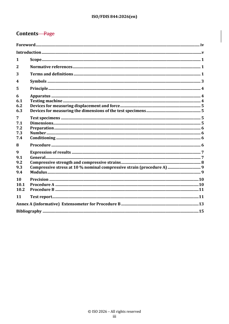
Contents Page
Foreword .iv
Introduction .v
1 Scope . 1
2 Normative references . 1
3 Terms and definitions . 1
4 Symbols . 3
5 Principle . 3
6 Apparatus . 4
6.1 Testing machine .4
6.2 Devices for measuring displacement and force .4
6.2.1 Displacement .4
6.2.2 Force .4
6.2.3 Calibration . . .5
6.3 Devices for measuring the dimensions of the test specimens .5
7 Test specimens . 5
7.1 Dimensions .5
7.2 Preparation .5
7.3 Number .5
7.4 Conditioning.5
8 Procedure . 6
9 Expression of results . 6
9.1 General .6
9.2 Compressive strength and compressive strains .8
9.2.1 Compressive strength .8
9.2.2 Nominal compressive strain (procedure A) .8
9.2.3 Compressive strain (procedure B) .8
9.3 Compressive stress at 10 % nominal compressive strain (procedure A) .8
9.4 Modulus.8
9.4.1 General .8
9.4.2 Nominal compressive modulus (procedure A) .9
9.4.3 Compressive modulus (procedure B) .9
10 Precision . 9
10.1 Procedure A .9
10.2 Procedure B .10
11 Test report . 10
Annex A (informative) Extensometer for Procedure B .12
Bibliography .13
iii
Foreword
ISO (the International Organization for Standardization) is a worldwide federation of national standards
bodies (ISO member bodies). The work of preparing International Standards is normally carried out through
ISO technical committees. Each member body interested in a subject for which a technical committee
has been established has the right to be represented on that committee. International organizations,
governmental and non-governmental, in liaison with ISO, also take part in the work. ISO collaborates closely
with the International Electrotechnical Commission (IEC) on all matters of electrotechnical standardization.
The procedures used to develop this document and those intended for its further maintenance are described
in the ISO/IEC Directives, Part 1. In particular, the different approval criteria needed for the different types
of ISO document should be noted. This document was drafted in accordance with the editorial rules of the
ISO/IEC Directives, Part 2 (see www.iso.org/directives).
ISO draws attention to the possibility that the implementation of this document may involve the use of (a)
patent(s). ISO takes no position concerning the evidence, validity or applicability of any claimed patent
rights in respect thereof. As of the date of publication of this document, ISO had not received notice of (a)
patent(s) which may be required to implement this document. However, implementers are cautioned that
this may not represent the latest information, which may be obtained from the patent database available at
www.iso.org/patents. ISO shall not be held responsible for identifying any or all such patent rights.
Any trade name used in this document is information given for the convenience of users and does not
constitute an endorsement.
For an explanation of the voluntary nature of standards, the meaning of ISO specific terms and expressions
related to conformity assessment, as well as information about ISO's adherence to the World Trade
Organization (WTO) principles in the Technical Barriers to Trade (TBT), see www.iso.org/iso/foreword.html.
This document was prepared by Technical Committee ISO/TC 61, Plastics, Subcommittee SC 10, Cellular
plastics, in collaboration with the European Committee for Standardization (CEN) Technical Committee
CEN/TC 249, Plastics, in accordance with the Agreement on technical cooperation between ISO and CEN
(Vienna Agreement).
This eighth edition cancels and replaces the seventh edition (ISO 844:2021), which has been technically
revised.
The main changes are as follows:
— the term “compression” changed to “compressive” throughout the document, including the title;
— the scope has been modified to include details of Procedure A and Procedure B;
— “relative deformation” has been changed to “compressive strain”;
— “nominal relative deformation” has been changed to “nominal compressive strain”;
— “necking” has been changed to the more descriptive “force-drop”.
Any feedback or questions on this document should be directed to the user’s national standards body. A
complete listing of these bodies can be found at www.iso.org/members.html.
iv
Introduction
For the determination of compressive properties, it is common practice to apply a uniform compressive
deformation to a standard test specimen, especially for quality assurance. However, the test specimen has
a complex and inhomogeneous deformation state, under compression, which is not subjected to further
analysis in such an evaluation. Measurement results are, therefore, not easily transferable to other test
specimens or products. This document describes Procedure A, which determines the nominal compressive
properties. Procedure B determines conventional compressive properties.
Procedure A employs relative plate displacement for the determination of compressive properties.
Procedure B employs displacement measuring devices directly positioned on the specimen (contact or
optical extensometer) or similar devices that measure the specimen displacement.
v
FINAL DRAFT International Standard ISO/FDIS 844:2026(en)
Rigid cellular plastics — Determination of compressive
properties
1 Scope
This document specifies methods for determining the compressive strength, the corresponding compressive
strain, the compressive stress at 10 % nominal compressive strain, and the compressive modulus of rigid
cellular plastics.
Two procedures are specified. Procedure A and Procedure B.
Procedure A utilizes the compression plate displacement for the nominal property determination. It is used
to determine:
— compressive strength and the corresponding nominal compressive strain;
— compressive stress at 10 % nominal compressive strain;
— nominal compressive modulus.
Procedure B uses an extensometer and determines the conventional properties. It is used to determine:
— compressive strength and the corresponding compressive strain;
— compressive modulus.
2 Normative references
The following documents are referred to in the text in such a way that some or all of their content constitutes
requirements of this document. For dated references, only the edition cited applies. For undated references,
the latest edition of the referenced document (including any amendments) applies.
ISO 291, Plastics — Standard atmospheres for conditioning and testing
ISO 1923, Cellular plastics and rubbers — Determination of linear dimensions
ISO 7500-1, Metallic materials — Calibration and verification of static uniaxial testing machines — Part 1:
Tension/compression testing machines — Calibration and verification of the force-measuring system
ISO 9513, Metallic materials — Calibration of extensometer systems used in uniaxial testing
3 Terms and definitions
For the purposes of this document, the following terms and definitions apply.
ISO and IEC maintain terminology databases for use in standardization at the following addresses:
— ISO Online browsing platform: available at https:// www .iso .org/ obp
— IEC Electropedia: available at https:// www .electropedia .org/
3.1
nominal compressive strain
ε
C
decrease in thickness per unit original thickness h of the test specimen
Note 1 to entry: It is expressed as a percentage.
Note 2 to entry: ε is the nominal compressive strain at σ (see 3.3).
Cm m
Note 3 to entry: Procedure A applies.
3.2
compressive strain
ε
decrease in length per unit original gage length l
o
Note 1 to entry: It is expressed as a percentage.
Note 2 to entry: ε is the compressive strain at σ (see 3.3).
m m
Note 3 to entry: Procedure B applies.
3.3
compressive strength
σ
m
maximum compressive force F divided by the initial cross-sectional area A of the test specimen when the
m 0
ε and the ε , respectively, < 10 %
C
Note 1 to entry: It is expressed in megapascals (MPa).
3.4
compressive stress at 10 % nominal compressive strain
σ
...
ISO/TC 61/SC 10/WG 12
Secretariat: SCC
Date: 2026-xx-xx03-13
Rigid cellular plastics — Determination of compressive properties
Plastiques alvéolaires rigides — Détermination des caractéristiques de compression
FDIS stage
TThhiis drs draafftt i is s susubbmmiitttteed d ttoo aa ppaarraallellel l vvoottee i inn IISSOO,, CCEEN.N.
All rights reserved. Unless otherwise specified, or required in the context of its implementation, no part of this publication
may be reproduced or utilized otherwise in any form or by any means, electronic or mechanical, including photocopying,
or posting on the internet or an intranet, without prior written permission. Permission can be requested from either ISO
at the address below or ISO'sISO’s member body in the country of the requester.
ISO Copyright Officecopyright office
CP 401 • Ch. de Blandonnet 8
CH-1214 Vernier, Geneva
Phone: + 41 22 749 01 11
Email: E-mail: copyright@iso.org
Website: www.iso.org
Published in Switzerland.
ii
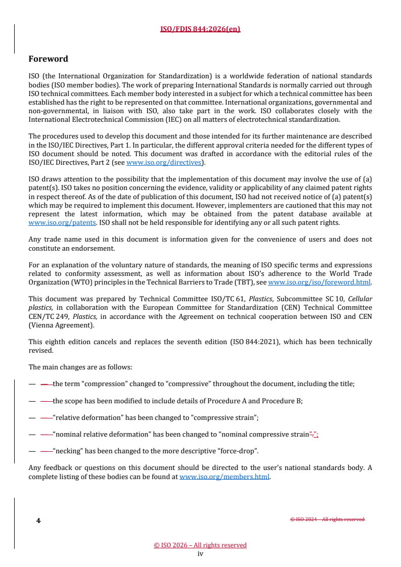
Contents Page
Foreword . iv
Introduction . v
1 Scope . 1
2 Normative references . 1
3 Terms and definitions . 1
4 Symbols . 3
5 Principle . 4
6 Apparatus . 4
6.1 Testing machine . 4
6.2 Devices for measuring displacement and force . 5
6.3 Devices for measuring the dimensions of the test specimens . 5
7 Test specimens . 5
7.1 Dimensions . 5
7.2 Preparation . 6
7.3 Number . 6
7.4 Conditioning . 6
8 Procedure . 6
9 Expression of results . 7
9.1 General . 7
9.2 Compressive strength and compressive strains . 8
9.3 Compressive stress at 10 % nominal compressive strain (procedure A) . 9
9.4 Modulus . 9
10 Precision . 10
10.1 Procedure A . 10
10.2 Procedure B . 11
11 Test report . 11
Annex A (informative) Extensometer for Procedure B . 13
Bibliography . 15
iii
Foreword
ISO (the International Organization for Standardization) is a worldwide federation of national standards
bodies (ISO member bodies). The work of preparing International Standards is normally carried out through
ISO technical committees. Each member body interested in a subject for which a technical committee has been
established has the right to be represented on that committee. International organizations, governmental and
non-governmental, in liaison with ISO, also take part in the work. ISO collaborates closely with the
International Electrotechnical Commission (IEC) on all matters of electrotechnical standardization.
The procedures used to develop this document and those intended for its further maintenance are described
in the ISO/IEC Directives, Part 1. In particular, the different approval criteria needed for the different types of
ISO document should be noted. This document was drafted in accordance with the editorial rules of the
ISO/IEC Directives, Part 2 (see www.iso.org/directives).
ISO draws attention to the possibility that the implementation of this document may involve the use of (a)
patent(s). ISO takes no position concerning the evidence, validity or applicability of any claimed patent rights
in respect thereof. As of the date of publication of this document, ISO had not received notice of (a) patent(s)
which may be required to implement this document. However, implementers are cautioned that this may not
represent the latest information, which may be obtained from the patent database available at
www.iso.org/patents. ISO shall not be held responsible for identifying any or all such patent rights.
Any trade name used in this document is information given for the convenience of users and does not
constitute an endorsement.
For an explanation of the voluntary nature of standards, the meaning of ISO specific terms and expressions
related to conformity assessment, as well as information about ISO's adherence to the World Trade
Organization (WTO) principles in the Technical Barriers to Trade (TBT), see www.iso.org/iso/foreword.html.
This document was prepared by Technical Committee ISO/TC 61, Plastics, Subcommittee SC 10, Cellular
plastics, in collaboration with the European Committee for Standardization (CEN) Technical Committee
CEN/TC 249, Plastics, in accordance with the Agreement on technical cooperation between ISO and CEN
(Vienna Agreement).
This eighth edition cancels and replaces the seventh edition (ISO 844:2021), which has been technically
revised.
The main changes are as follows:
— — the term “compression” changed to “compressive” throughout the document, including the title;
— — the scope has been modified to include details of Procedure A and Procedure B;
— — “relative deformation” has been changed to “compressive strain”;
— — “nominal relative deformation” has been changed to “nominal compressive strain”.”;
— — “necking” has been changed to the more descriptive “force-drop”.
Any feedback or questions on this document should be directed to the user’s national standards body. A
complete listing of these bodies can be found at www.iso.org/members.html.
iv
Introduction
For the determination of compressive properties, it is common practice to apply ana uniform compressive
deformation to a standard test specimen, especially for quality assurance. However, the test specimen has a
complex and inhomogeneous deformation state, under compression, which is not subjected to further analysis
in such an evaluation. Measurement results are, therefore, not easily transferable to other test specimens or
products. This document describes Procedure A, which determines the nominal compressive properties.
Procedure B determines conventional compressive properties.
Procedure A employs relative plate displacement for the determination of compressive properties.
Procedure B employs displacement measuring devices directly positioned on the specimen (contact or optical
extensometer) or similar devices that measure the specimen displacement.
v
FINAL DRAFT International Standard ISO/FDIS 844:2026(en)
Rigid cellular plastics — Determination of compressive properties
1 Scope
This document specifies methods for determining the compressive strength, the corresponding compressive
strain, the compressive stress at 10 % nominal compressive strain, and the compressive modulus of rigid
cellular plastics.
Two procedures are specified. Procedure A and Procedure B.
Procedure A utilizes the compression plate displacement for the nominal property determination. It is used to
determine:
— — compressive strength and the corresponding nominal compressive strain;
— — compressive stress at 10 % nominal compressive strain;
— — nominal compressive modulus.
Procedure B uses an extensometer and determines the conventional properties. It is used to determine:
— — compressive strength and the corresponding compressive strain;
— — compressive modulus.
2 Normative references
The following documents are referred to in the text in such a way that some or all of their content constitutes
requirements of this document. For dated references, only the edition cited applies. For undated references,
the latest edition of the referenced document (including any amendments) applies.
ISO 291, Plastics — Standard atmospheres for conditioning and testing
ISO 1923, Cellular plastics and rubbers — Determination of linear dimensions
ISO 7500--1, Metallic materials — Calibration and verification of static uniaxial testing machines — Part 1:
Tension/compression testing machines — Calibration and verification of the force-measuring system
ISO 9513, Metallic materials — Calibration of extensometer systems used in uniaxial testing
3 Terms and definitions
For the purposes of this document, the following terms and definitions apply.
ISO and IEC maintain terminologicalterminology databases for use in standardization at the following
addresses:
— — ISO Online browsing platform: available at https://www.iso.org/obp
— — IEC Electropedia: available at https://www.electropedia.org/
3.1 3.1
nominal compressive strain
εC
decrease in thickness per unit original thickness h of the test specimen
Note 1 to entry: It is expressed as a percentage.
Note 2 to entry: εCm is the nominal compressive strain at σm (see 3.33.3).).
Note 3 to entry: Procedure A applies.
3.2 3.2
compressive strain
ε
decrease in length per unit original gage length l
o
Note 1 to entry: It is expressed as a percentage.
Note 2 to entry: ε is the compressive strain at σ (see 3.33.3).).
m m
Note 3 to entry: Procedure B applies.
3.3 3.3
compressive strength
σ
m
maximum compressive force F divided by the initial cross-sectional area A of the test specimen when the ε
m 0
and the ε , respectively, < 10 %
C
Note 1 to entry: It is expressed in megapascals (MPa).
3.4 3.4
compressive stress at 10 % nominal compressive strain
σ
ratio of the compressive force F at 10 % nominal compressive strain ε to the initial cross-sectional area
10 C10
A of the test specimen
Note 1 to entry: It is expressed in megapascals (MPa).
Note 2 to entry: Procedure A applies
3.5 3.5
nominal compressive modulus
EC
difference in compressive stress divided by the difference in corresponding nominal compressive strain below
the nominal proportional limit
Note 1 to entry: It is expressed in megapascals (MPa).
Note 2 to entry: Procedure A applies.
3.6 3.6
compressive modulus
E
difference in compressive stress divided by the difference in corresponding compressive strain below the
proportional limit
Note 1 to entry: It is expressed in megapascals (MPa).
Note 2 to entry: Procedure B applies.
3.7 3.7
nominal proportional limit
X
Ce
upper displacement limit of the linear part of the force -nominal displacement curve
Note 1 to entry: It is expressed in millimetres (mm).
Note 2 to entry: Procedure A applies.
3.8 3.8
proportional limit
X
e
upper displacement limit of the linear part of the force–displacement curve
Note 1 to entry: It is expressed in millimetres (mm).
Note 2 to entry: Procedure B applies.
4 Symbols
Symb Definition Unit
ol
A initial cross-sectional area square millimetres
E compressive modulus megapascals
E nominal compressive modulus megapascals
C
Fe force at proportional limit newtons
F force at nominal proportional limit newtons
Ce
Fm maximum force newtons
F force at 10 % nominal compressive strain newtons
h0 initial thickness of test specimen millimetres
l initial gage length of the extensometer millimetres
o
Ra compression plate surface roughness micrometres
t compression plate thickness millimetres
X proportional limit millimetres
e
XCe nominal proportional limit millimetres
X displacement at maximum force millimetres
m
XCm nominal displacement at maximum force millimetres
X displacement at 10 % nominal compressive strain millimetres
C10
Symb Definition Unit
ol
εm compressive strain at compressive strength percent
ε nominal compressive strain at compressive strength percent
Cm
εC10 10 % nominal compressive strain percent
σ compressive stress at proportional limit megapascals
e
σm compressive strength megapascals
σ compressive stress at 10 % nominal compressive strain megapascals
5 Principle
A compressive force is applied perpendicular to the faces of the test specimen positioned between two rigid
plates using a constant displacement loading. Nominal compressive properties are determined from the
stress-strain data produced using the relative plate displacement as the displacement indicator. In contrast,
compressive properties are determined with an extensometer that provides a direct measurement of the test
specimen deformation.
6 Apparatus
6.1 Testing
...
PROJET FINAL
Norme
internationale
ISO/TC 61/SC 10
Plastiques alvéolaires rigides —
Secrétariat: SCC
Détermination des caractéristiques
Début de vote:
de compression
2026-03-27
Rigid cellular plastics — Determination of compressive properties
Vote clos le:
2026-05-22
LES DESTINATAIRES DU PRÉSENT PROJET SONT
INVITÉS À PRÉSENTER, AVEC LEURS OBSERVATIONS,
NOTIFICATION DES DROITS DE PROPRIÉTÉ DONT ILS
AURAIENT ÉVENTUELLEMENT CONNAISSANCE ET À
FOURNIR UNE DOCUMENTATION EXPLICATIVE.
OUTRE LE FAIT D’ÊTRE EXAMINÉS POUR
ÉTABLIR S’ILS SONT ACCEPTABLES À DES FINS
INDUSTRIELLES, TECHNOLOGIQUES ET COM-MERCIALES,
AINSI QUE DU POINT DE VUE DES UTILISATEURS, LES
PROJETS DE NORMES
TRAITEMENT PARALLÈLE ISO/CEN
INTERNATIONALES DOIVENT PARFOIS ÊTRE CONSIDÉRÉS
DU POINT DE VUE DE LEUR POSSI BILITÉ DE DEVENIR DES
NORMES POUVANT
SERVIR DE RÉFÉRENCE DANS LA RÉGLEMENTATION
NATIONALE.
Numéro de référence
PROJET FINAL
Norme
internationale
ISO/TC 61/SC 10
Plastiques alvéolaires rigides —
Secrétariat: SCC
Détermination des caractéristiques
Début de vote:
de compression
2026-03-27
Rigid cellular plastics — Determination of compressive properties
Vote clos le:
2026-05-22
LES DESTINATAIRES DU PRÉSENT PROJET SONT
INVITÉS À PRÉSENTER, AVEC LEURS OBSERVATIONS,
NOTIFICATION DES DROITS DE PROPRIÉTÉ DONT ILS
AURAIENT ÉVENTUELLEMENT CONNAISSANCE ET À
FOURNIR UNE DOCUMENTATION EXPLICATIVE.
DOCUMENT PROTÉGÉ PAR COPYRIGHT
OUTRE LE FAIT D’ÊTRE EXAMINÉS POUR
ÉTABLIR S’ILS SONT ACCEPTABLES À DES FINS
© ISO 2026 INDUSTRIELLES, TECHNOLOGIQUES ET COM-MERCIALES,
AINSI QUE DU POINT DE VUE DES UTILISATEURS, LES
Tous droits réservés. Sauf prescription différente ou nécessité dans le contexte de sa mise en œuvre, aucune partie de cette
PROJETS DE NORMES
TRAITEMENT PARALLÈLE ISO/CEN
INTERNATIONALES DOIVENT PARFOIS ÊTRE CONSIDÉRÉS
publication ne peut être reproduite ni utilisée sous quelque forme que ce soit et par aucun procédé, électronique ou mécanique,
DU POINT DE VUE DE LEUR POSSI BILITÉ DE DEVENIR DES
y compris la photocopie, ou la diffusion sur l’internet ou sur un intranet, sans autorisation écrite préalable. Une autorisation peut
NORMES POUVANT
être demandée à l’ISO à l’adresse ci-après ou au comité membre de l’ISO dans le pays du demandeur.
SERVIR DE RÉFÉRENCE DANS LA RÉGLEMENTATION
NATIONALE.
ISO copyright office
Case postale 401 • Ch. de Blandonnet 8
CH-1214 Vernier, Genève
Tél.: +41 22 749 01 11
E-mail: copyright@iso.org
Web: www.iso.org
Publié en Suisse Numéro de référence
ii
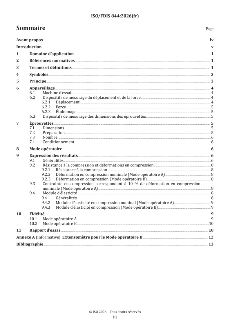
Sommaire Page
Avant-propos .iv
Introduction .v
1 Domaine d’application . 1
2 Références normatives . 1
3 Termes et définitions . 1
4 Symboles . 3
5 Principe. 3
6 Appareillage . 4
6.1 Machine d’essai .4
6.2 Dispositifs de mesurage du déplacement et de la force .4
6.2.1 Déplacement .4
6.2.2 Force .5
6.2.3 Étalonnage .5
6.3 Dispositifs de mesurage des dimensions des éprouvettes .5
7 Éprouvettes. 5
7.1 Dimensions .5
7.2 Préparation .5
7.3 Nombre .6
7.4 Conditionnement .6
8 Mode opératoire . 6
9 Expression des résultats . 6
9.1 Généralités .6
9.2 Résistance à la compression et déformations en compression .8
9.2.1 Résistance à la compression .8
9.2.2 Déformation en compression nominale (Mode opératoire A) .8
9.2.3 Déformation en compression (Mode opératoire B) .8
9.3 Contrainte en compression correspondant à 10 % de déformation en compression
nominale (Mode opératoire A) .8
9.4 Module d’élasticité . .8
9.4.1 Généralités .8
9.4.2 Module d’élasticité en compression nominal (Mode opératoire A) .9
9.4.3 Module d’élasticité en compression (Mode opératoire B) .9
10 Fidélité . 9
10.1 Mode opératoire A .9
10.2 Mode opératoire B .10
11 Rapport d’essai .10
Annexe A (informative) Extensomètre pour le Mode opératoire B .12
Bibliographie .13
iii
Avant-propos
L’ISO (Organisation internationale de normalisation) est une fédération mondiale d’organismes nationaux
de normalisation (comités membres de l’ISO). L’élaboration des Normes internationales est en général
confiée aux comités techniques de l’ISO. Chaque comité membre intéressé par une étude a le droit de faire
partie du comité technique créé à cet effet. Les organisations internationales, gouvernementales et non
gouvernementales, en liaison avec l’ISO participent également aux travaux. L’ISO collabore étroitement avec
la Commission électrotechnique internationale (IEC) en ce qui concerne la normalisation électrotechnique.
Les procédures utilisées pour élaborer le présent document et celles destinées à sa mise à jour sont
décrites dans les Directives ISO/IEC, Partie 1. Il convient, en particulier, de prendre note des différents
critères d’approbation requis pour les différents types de documents ISO. Le présent document a
été rédigé conformément aux règles de rédaction données dans les Directives ISO/IEC, Partie 2 (voir
www.iso.org/directives).
L’ISO attire l’attention sur le fait que la mise en application du présent document peut entraîner l’utilisation
d’un ou de plusieurs brevets. L’ISO ne prend pas position quant à la preuve, à la validité et à l’applicabilité de
tout droit de brevet revendiqué à cet égard. À la date de publication du présent document, l’ISO n’avait pas
reçu notification qu’un ou plusieurs brevets pouvaient être nécessaires à sa mise en application. Toutefois,
il y a lieu d’avertir les responsables de la mise en application du présent document que des informations
plus récentes sont susceptibles de figurer dans la base de données de brevets, disponible à l’adresse
www.iso.org/brevets. L’ISO ne saurait être tenue pour responsable de ne pas avoir identifié tout ou partie de
tels droits de brevet.
Les appellations commerciales éventuellement mentionnées dans le présent document sont données pour
information, par souci de commodité, à l’intention des utilisateurs et ne sauraient constituer un engagement.
Pour une explication de la nature volontaire des normes, la signification des termes et expressions
spécifiques de l’ISO liés à l’évaluation de la conformité, ou pour toute information au sujet de l’adhésion de
l’ISO aux principes de l’Organisation mondiale du commerce (OMC) concernant les obstacles techniques au
commerce (OTC), voir www.iso.org/avant-propos.
Le présent document a été élaboré par le comité technique ISO/TC 61, Plastiques, sous-comité SC 10,
Plastiques alvéolaires, en collaboration avec le comité technique CEN/TC 249, Plastiques, du Comité européen
de normalisation (CEN), conformément à l’Accord de coopération technique entre l’ISO et le CEN (Accord de
Vienne).
Cette huitième édition annule et remplace la septième édition (ISO 844:2021), qui a fait l’objet d’une révision
technique.
Les principales modifications sont les suivantes:
— le mot «compression» a été remplacé par «compressive» dans l’ensemble du document anglais, y compris
dans le titre;
— le domaine d’application a été modifié pour inclure des détails sur le Mode opératoire A et le Mode
opératoire B;
— «déformation relative» a été remplacé par «déformation en compression»;
— «déformation relative nominale» a été remplacé par «déformation en compression nominale»;
— «rétrécissement» a été remplacé par «diminution de la force».
Il convient que l’utilisateur adresse tout retour d’information ou toute question concernant le présent
document à l’organisme national de normalisation de son pays. Une liste exhaustive desdits organismes se
trouve à l’adresse www.iso.org/fr/members.html.
iv
Introduction
Pour la détermination des caractéristiques de compression, il est d’usage d’appliquer une déformation en
compression uniforme à une éprouvette normalisée, en particulier pour l’assurance qualité. Cependant,
l’éprouvette présente un état de déformation complexe et non homogène quand elle est comprimée, qui ne
fait pas l’objet d’une analyse supplémentaire lors d’une telle évaluation. Les résultats de mesure ne peuvent
donc pas être facilement transférés à d’autres éprouvettes ou produits. Le présent document décrit le Mode
opératoire A, qui détermine les caractéristiques nominales en compression. Le Mode opératoire B détermine
les caractéristiques conventionnelles en compression.
Le Mode opératoire A utilise le mouvement relatif du plateau pour la détermination des caractéristiques de
compression.
Le Mode opératoire B utilise des dispositifs de mesure du déplacement positionnés directement sur
l’éprouvette (extensomètre par contact ou optique) ou des dispositifs similaires qui mesurent le déplacement
de l’éprouvette.
v
PROJET FINAL Norme internationale ISO/FDIS 844:2026(fr)
Plastiques alvéolaires rigides — Détermination des
caractéristiques de compression
1 Domaine d’application
Le présent document spécifie des méthodes permettant de déterminer la résistance à la compression, la
déformation en compression correspondante, la contrainte en compression correspondant à 10 % de
déformation en compression nominale et le module d’élasticité en compression des plastiques alvéolaires
rigides.
Deux modes opératoires sont spécifiés: le Mode opératoire A et le Mode opératoire B.
Le Mode opératoire A utilise le déplacement du plateau de compression pour la détermination de la
caractéristique nominale. Il doit être utilisé pour déterminer:
— la résistance à la compression et la déformation en compression nominale correspondante;
— la contrainte en compression correspondant à 10 % de déformation en compression nominale;
— le module d’élasticité en compression nominal.
Le Mode opératoire B utilise un extensomètre et détermine les caractéristiques conventionnelles. Il doit être
utilisé pour déterminer:
— la résistance à la compression et la déformation en compression correspondante;
— le module d’élasticité en compression.
2 Références normatives
Les documents suivants sont cités dans le texte de sorte qu’ils constituent, pour tout ou partie de leur
contenu, des exigences du présent document. Pour les références datées, seule l’édition citée s’applique. Pour
les références non datées, la dernière édition du document de référence s’applique (y compris les éventuels
amendements).
ISO 291, Plastiques — Atmosphères normales de conditionnement et d'essai
ISO 1923, Plastiques et caoutchoucs alvéolaires — Détermination des dimensions linéaires
ISO 7500-1, Matériaux métalliques — Étalonnage et vérification des machines pour essais statiques uniaxiaux
— Partie 1: Machines d'essai de traction/compression — Étalonnage et vérification du système de mesure de
force
ISO 9513, Matériaux métalliques — Étalonnage des chaînes extensométriques utilisées lors d'essais uniaxiaux
3 Termes et définitions
Pour les besoins du présent document, les termes et définitions suivants s’appliquent.
L’ISO et l’IEC tiennent à jour des bases de données terminologiques destinées à être utilisées en normalisation,
consultables aux adresses suivantes:
— ISO Online browsing platform: disponible à l’adresse https:// www .iso .org/ obp
— IEC Electropedia: disponible à l’adresse https:// www .electropedia .org/
3.1
déformation en compression nominale
ε
C
diminution de l'épaisseur par unité d'épaisseur initiale h de l'éprouvette
Note 1 à l'article: Elle est exprimée en pourcentage.
Note 2 à l'article: ε est la déformation en compression nominale correspondant à σ (voir 3.3).
Cm m
Note 3 à l'article: Le Mode opératoire A s’applique.
3.2
déformation en compression
ε
diminution de la longueur par unité de longueur de référence initiale l
o
Note 1 à l'article: Elle est exprimée en pourcentage.
Note 2 à l'article: ε est la déformation en compression correspondant à σ (voir 3.3).
m m
Note 3 à l'article: Le Mode opératoire B s’applique.
3.3
résistance à la compression
σ
m
rapport de la force maximale de compression F à l’aire initiale de la section transversale de l’éprouvette A
m 0
lorsque ε ou ε , respectivement, est < 10 %
C
Note 1 à l'article: Elle est exprimée en mégapascals (MPa).
3.4
contrainte en compression correspondant à 10 % de déformation en compression nominale
σ
rapport de la force de compression F correspondant à 10 % de déformation en compression nominale ε ,
10 C10
à l’aire initiale de la section transversale de l’éprouvette
Note 1 à l'article: Elle est exprimée en mégapascals (MPa).
Note 2 à l'article: Le Mode opératoire A s’applique.
3.5
module d’élasticité en compression nominal
E
C
rapport de la différence de contrainte en compression à la différence de déformation en compression
nominale correspondante en deçà de la limite proportionnelle nominale
Note 1 à l'article: Il est exprimé en mégapascals (MPa).
Note 2 à l'article: Le Mode opératoire A s’applique.
3.6
module d’élasticité en compression
E
rapport de la différence de contrainte en compression à la dif
...