

ISO/FDIS 1456
(Main)Metallic and other inorganic coatings — Electrodeposited coatings of nickel, nickel plus chromium, copper plus nickel and of copper plus nickel plus chromium
- Abstract
ISO 1456:2009 specifies requirements for decorative nickel, nickel plus chromium, copper plus nickel and copper plus nickel plus chromium coatings that are applied to iron, steel, zinc alloys, copper and copper alloys, and to aluminium and aluminium alloys, to provide an attractive appearance and enhanced corrosion resistance. Coating designations are specified that differ in thickness and type, and guidance is given on selecting the coating designation appropriate for the service conditions to which the coated product will be exposed. ISO 1456:2009 does not specify the surface condition required by the basis metal prior to the coating process, and is not applicable to coatings on sheet, strip or wire in the non-fabricated form nor to threaded fasteners or coil springs.
- Status
- Not Published
- Technical Committee
- ISO/TC 107/SC 3 - Electrodeposited coatings and related finishes
- Drafting Committee
- ISO/TC 107/SC 3 - Electrodeposited coatings and related finishes
- Current Stage
- 5020 - FDIS ballot initiated: 2 months. Proof sent to secretariat
- Start Date
- 27-Aug-2026
- Completion Date
- 27-Aug-2026
Buy Documents

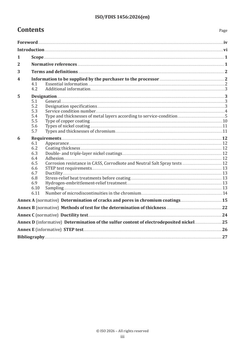

ISO/FDIS 1456 - Metallic and other inorganic coatings — Electrodeposited coatings of nickel, nickel plus chromium, copper plus nickel and of copper plus nickel plus chromium
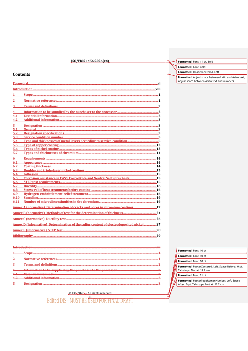
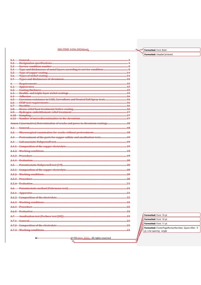
REDLINE ISO/FDIS 1456 - Metallic and other inorganic coatings — Electrodeposited coatings of nickel, nickel plus chromium, copper plus nickel and of copper plus nickel plus chromium

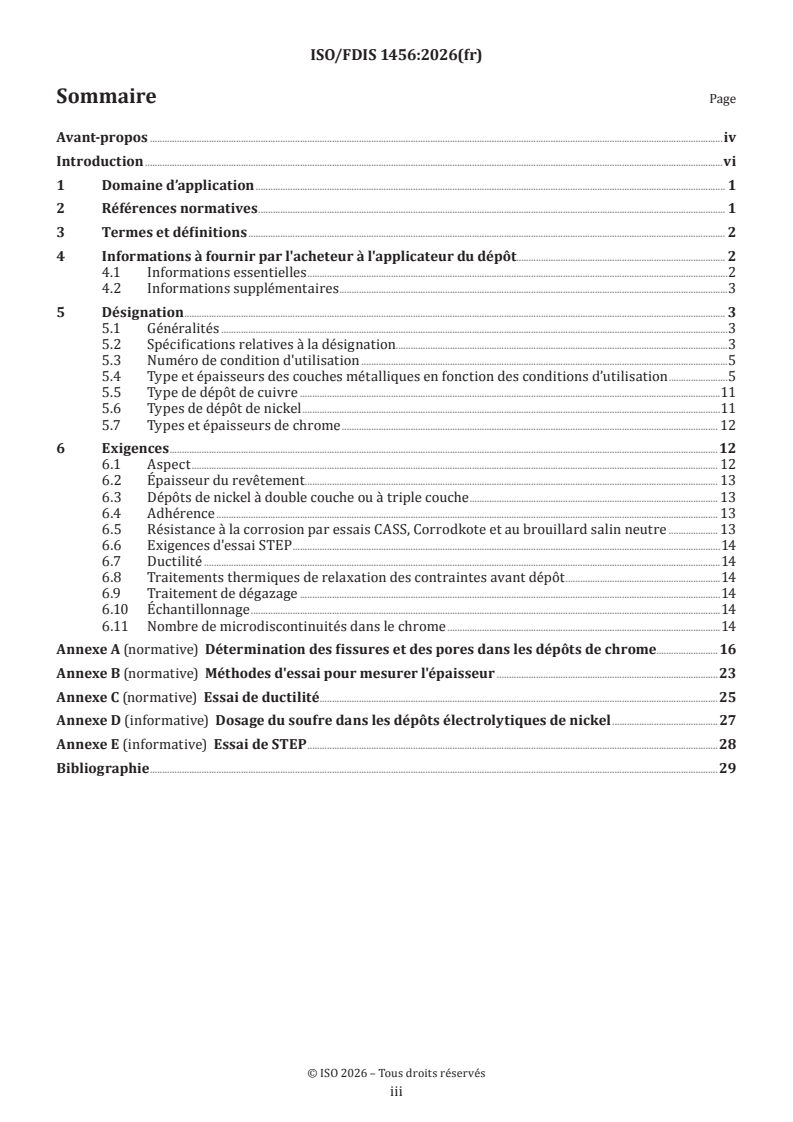
ISO/FDIS 1456 - Revêtements métalliques et autres revêtements inorganiques — Dépôts électrolytiques de nickel, de nickel plus chrome, de cuivre plus nickel et de cuivre plus nickel plus chrome
ISO/FDIS 1456 sets out a designation and test framework for decorative electrodeposited coatings of nickel, nickel plus chromium, copper plus nickel, and copper plus nickel plus chromium. ISO publishes it for manufacturers, platers, purchasers, and test laboratories that need to specify these finishes on iron, steel, zinc alloys, copper and copper alloys, and aluminium and aluminium alloys.
What does ISO/FDIS 1456 specify?
ISO/FDIS 1456 specifies the coating systems, designation rules, purchaser information, and acceptance requirements for decorative nickel-based coatings intended to improve appearance and corrosion resistance. The document also tells users how to choose a coating designation for the expected service conditions and how to verify the result by thickness, adhesion, corrosion, ductility, and related tests.
ISO/FDIS 1456 is organized into six clauses: scope, normative references, terms and definitions, information to be supplied by the purchaser, designation, and requirements. It also has five annexes that cover crack and pore measurement, coating thickness methods, ductility testing, sulfur determination in nickel, and the STEP test.
| Annex | What it covers |
|---|---|
| Annex A | Determination of cracks and pores in chromium coatings |
| Annex B | Methods of test for the determination of thickness |
| Annex C | Ductility test |
| Annex D | Determination of the sulfur content of electrodeposited nickel |
| Annex E | STEP test |
What are the key requirements of ISO/FDIS 1456?
ISO/FDIS 1456 requires the purchaser to define the coating clearly before work starts, and it uses a structured designation to tie the finish to the substrate, layer build-up, and service conditions. In practice, this is the part that prevents ambiguity in orders, drawings, and inspection plans.
1. Purchaser information fixes the technical target
ISO/FDIS 1456 asks the purchaser to state the reference to the document, the designation, the significant surfaces, the service condition and/or required corrosion resistance, the required appearance, the nickel and chromium types, the corrosion and adhesion tests to be used, tolerated defects on non-significant surfaces, rack-mark locations, stress-relief and hydrogen-embrittlement requirements, and sampling and acceptance levels. This matters because the coating cannot be judged correctly unless the part, the finish, and the test basis are all defined up front.
2. The designation encodes the whole coating build-up
ISO/FDIS 1456 specifies a designation order that includes the basis metal, optional alloy identification, optional copper undercoat, nickel layer thickness and type, any further coating such as chromium, and any stress-relief or embrittlement-relief heat treatment. The designation uses symbols such as Fe, Zn, Cu and Al for the basis metal, Ni for nickel, and Cr for chromium, so one line can identify the complete coating stack for ordering and inspection.
The document also defines the service-condition number from 1 to 5, where 1 is mild indoor service and 5 is exceptionally severe outdoor service requiring long-term protection. In practice, this number is the main way the purchaser matches coating thickness and coating type to the expected environment.
3. Substrate-specific layer sequences are part of the selection
ISO/FDIS 1456 links the coating build-up to the substrate family, and it gives separate designation tables for ferrous materials, zinc alloys, copper and copper alloys, and aluminium and aluminium alloys. It also requires an initial metal layer on ferrous materials before copper from acid solutions, and on stainless steel and zinc before copper from acid solutions and before nickel plating; aluminium and aluminium alloys need a specific initial treatment.
This matters because adhesion and corrosion resistance depend on the starting surface, not only on the final decorative finish. For steel and zinc, the document also explains when a copper strike is used and how ductile acid copper is applied.
4. Nickel and chromium types are classified by performance-relevant symbols
ISO/FDIS 1456 distinguishes nickel types b, i, p, s and d. The symbols cover bright or semi-bright nickel, high-sulfur nickel, mechanically polished nickel, sulfur-free nickel, and double- or triple-layer nickel. The document also defines chromium types b, r, mc and mp for black, regular, micro-cracked, and micro-porous chromium.
This is important in practice because appearance, ductility, and corrosion behaviour change with the nickel structure and with the chromium discontinuity pattern. For micro-porous chromium, the document requires the pores to be invisible to normal vision and to be present in sufficient number for corrosion protection.
5. Appearance and thickness are basic acceptance checks
ISO/FDIS 1456 requires the significant surface to be free from clearly visible defects such as blisters, pits, roughness, non-plated areas, stains, and discoloration, and it calls for a uniform agreed colour. It also states that the coating thickness in the designation is the minimum local thickness, measured on the significant surface at points that can be touched by a 20 mm ball unless the purchaser specifies otherwise.
For a buyer or quality manager, this means visible finish and local thickness both matter. A part can meet average thickness and still fail if the significant surface shows defects or if local thickness is too low at accessible points.
6. Adhesion, corrosion resistance, ductility, and special tests are controlled
ISO/FDIS 1456 requires the coating and the individual layers of multilayer nickel to be adherent enough to pass either the file test or the thermal shock test in ISO 2819. It requires one of the listed corrosion tests - CASS, Corrodkote, or Neutral Salt Spray - for the time linked to the service-condition number, and the resulting specimens are rated in accordance with ISO 10289.
The document also ties multilayer nickel performance to the STEP test when the purchaser asks for it, and it requires the ductility of the semi-bright nickel layer in multilayer systems to meet Table 5 when tested by Annex C. For high-strength steels, it calls for stress-relief heat treatment before coating and hydrogen-embrittlement-relief heat treatment after coating, with effectiveness checked by the referenced hydrogen-related test methods when specified.
7. Sampling and chromium discontinuities are part of conformity
ISO/FDIS 1456 states that sampling should be selected from ISO 4519 and that the acceptance levels are to be agreed by the purchaser. It also adds requirements for the number of microdiscontinuities in chromium, especially for micro-porous chromium, where the pore count is a key part of corrosion performance.
That means inspection is not limited to one finished part. The production lot, the sampling plan, and the chromium pore structure all affect whether the coating can be accepted.
What terms does ISO/FDIS 1456 define?
- Service-condition number - A 1 to 5 scale that links the coating build-up and thickness to the severity of the intended environment.
- Significant surface - The surface area that matters for appearance and service performance, and on which the coating is judged.
- Minimum local thickness - The smallest coating thickness allowed at a specified point on the significant surface.
- Micro-cracked chromium (Crmc) - Chromium with a closed network of fine cracks over the significant surface, used to improve corrosion performance.
- Micro-porous chromium (Crmp) - Chromium with a very high pore density over a special nickel layer, used to support corrosion resistance.
- STEP test - A method for measuring electrochemical potential differences between individual nickel layers in multilayer nickel deposits.
- SR - Stress-relief heat treatment applied before electroplating.
- ER - Hydrogen-embrittlement-relief heat treatment applied after electroplating.
Who uses ISO/FDIS 1456?
ISO/FDIS 1456 is used by electroplaters, coating suppliers, design engineers, buyers, and quality managers who specify decorative nickel-based finishes on manufactured articles. It is also used by inspection and laboratory personnel who measure coating thickness, check adhesion, rate corrosion tests, and evaluate chromium cracks, pores, and nickel layer structure.
The document is especially relevant in sectors that use decorative corrosion-resistant finishes on metal parts such as consumer hardware, transport components, fittings, and other manufactured articles where both appearance and durability matter.
What changed in ISO/FDIS 1456 from the previous edition?
ISO/FDIS 1456 is the fifth edition and cancels and replaces ISO 1456:2009. The foreword states that it has been technically revised.
The main changes listed are:
- a new subclause 5.4 with a better explanation of Tables 1 to 4
- a technical correction in Tables 1 and 2 removing the option to plate Cu10a from a cyanide electrolyte
- improved consistency between Table 5 and Annex E
- updated requirements for Crmp, including minimum and maximum local thickness
- new requirements for the number of microdiscontinuities in Crmp, with Annex A updated accordingly
- a new reference to ISO 16866 for the STEP test and a shorter Annex E
- ISO 9227 added as a normative reference
- further explanation added to the x-ray spectrometry thickness method in B.3.3
Which standards are used with ISO/FDIS 1456?
ISO/FDIS 1456 refers to several standards that supply test methods, definitions, and related requirements:
| Standard | Contribution |
|---|---|
| ISO 1463 | Microscopical thickness measurement and polished-section work |
| ISO 2064 | Definitions and conventions for thickness measurement |
| ISO 2080 | Surface treatment vocabulary |
| ISO 2177 | Coulometric thickness measurement by anodic dissolution |
| ISO 2361 | Magnetic thickness method for nickel coatings |
| ISO 2819 | Adhesion test methods |
| ISO 3497 | X-ray spectrometric thickness measurement |
| ISO 3543 | Beta backscatter thickness measurement |
| ISO 4541 | Corrodkote corrosion test |
| ISO 9227 | Salt spray tests |
| ISO 10289 | Corrosion test rating of coated specimens |
| ISO 10587 | Residual embrittlement test for threaded articles and rods |
| ISO 15724 | Diffusible hydrogen measurement in steels |
| ISO 16348 | Appearance terminology |
| ISO 16866 | STEP test for multilayer nickel deposits |
| ISO 24251-1 | Fundamentals and measures for hydrogen-assisted brittle fracture |
The document also names related standards and parts such as ISO 27830, ISO 4519, ISO 27831-2, ISO 9220, ISO 4525, ISO 4526, and ISO 6158 for designation, sampling, preparation, SEM thickness measurement, and related decorative or engineering coatings.
What does the ISO/FDIS 1456 document contain?
ISO/FDIS 1456 contains designation tables for coating systems on different substrates, service-condition guidance, and summaries of the required nickel and chromium layer types. It also includes a corrosion-test table that links service conditions to test type and duration.
Annex A contains several ways to reveal and count cracks or pores in chromium coatings, including microscopical examination, copper sulfate-based methods, the Fuhrmann test, and an anodization test. Annex B collects destructive and non-destructive thickness methods, including microscopical, coulometric, SEM, magnetic, beta backscatter, and x-ray spectrometry methods.
Annex C gives the bend test for ductility, using a mandrel and a 180° bend. Annex D gives two chemical routes for measuring sulfur in electrodeposited nickel. Annex E explains the STEP test and the kind of potential differences expected in double- and triple-layer nickel coatings.
Relations
- Effective Date
- 12-Feb-2026
- Effective Date
- 18-Nov-2023
- Effective Date
- 04-Nov-2023
Buy Documents
ISO/FDIS 1456 - Metallic and other inorganic coatings — Electrodeposited coatings of nickel, nickel plus chromium, copper plus nickel and of copper plus nickel plus chromium
REDLINE ISO/FDIS 1456 - Metallic and other inorganic coatings — Electrodeposited coatings of nickel, nickel plus chromium, copper plus nickel and of copper plus nickel plus chromium
ISO/FDIS 1456 - Revêtements métalliques et autres revêtements inorganiques — Dépôts électrolytiques de nickel, de nickel plus chrome, de cuivre plus nickel et de cuivre plus nickel plus chrome
Get Certified
Connect with accredited certification bodies for this standard

DVS-ZERT GmbH
German welding certification society.
CARES (UK Certification Authority for Reinforcing Steels)
UK certification for reinforcing steels and construction.
EWF/IIW (European/International Welding Federation)
International welding personnel certification.
Sponsored listings
Frequently Asked Questions
ISO/FDIS 1456 is a draft published by the International Organization for Standardization (ISO). Its full title is "Metallic and other inorganic coatings — Electrodeposited coatings of nickel, nickel plus chromium, copper plus nickel and of copper plus nickel plus chromium". This standard covers: ISO 1456:2009 specifies requirements for decorative nickel, nickel plus chromium, copper plus nickel and copper plus nickel plus chromium coatings that are applied to iron, steel, zinc alloys, copper and copper alloys, and to aluminium and aluminium alloys, to provide an attractive appearance and enhanced corrosion resistance. Coating designations are specified that differ in thickness and type, and guidance is given on selecting the coating designation appropriate for the service conditions to which the coated product will be exposed. ISO 1456:2009 does not specify the surface condition required by the basis metal prior to the coating process, and is not applicable to coatings on sheet, strip or wire in the non-fabricated form nor to threaded fasteners or coil springs.
ISO 1456:2009 specifies requirements for decorative nickel, nickel plus chromium, copper plus nickel and copper plus nickel plus chromium coatings that are applied to iron, steel, zinc alloys, copper and copper alloys, and to aluminium and aluminium alloys, to provide an attractive appearance and enhanced corrosion resistance. Coating designations are specified that differ in thickness and type, and guidance is given on selecting the coating designation appropriate for the service conditions to which the coated product will be exposed. ISO 1456:2009 does not specify the surface condition required by the basis metal prior to the coating process, and is not applicable to coatings on sheet, strip or wire in the non-fabricated form nor to threaded fasteners or coil springs.
ISO/FDIS 1456 is classified under the following ICS (International Classification for Standards) categories: 25.220.40 - Metallic coatings. The ICS classification helps identify the subject area and facilitates finding related standards.
ISO/FDIS 1456 has the following relationships with other standards: It is inter standard links to FprEN ISO 1456, ISO/IEC/IEEE 24774:2021, ISO 1456:2009. Understanding these relationships helps ensure you are using the most current and applicable version of the standard.
ISO/FDIS 1456 is available in PDF format for immediate download after purchase. The document can be added to your cart and obtained through the secure checkout process. Digital delivery ensures instant access to the complete standard document.
Standards Content (Sample)
FINAL DRAFT
International
Standard
ISO/TC 107/SC 3
Metallic and other inorganic
Secretariat: KATS
coatings — Electrodeposited
Voting begins on:
coatings of nickel, nickel plus
2026-08-27
chromium, copper plus nickel
Voting terminates on:
and of copper plus nickel plus
2026-10-22
chromium
Revêtements métalliques et autres revêtements inorganiques —
Dépôts électrolytiques de nickel, de nickel plus chrome, de cuivre
plus nickel et de cuivre plus nickel plus chrome
RECIPIENTS OF THIS DRAFT ARE INVITED TO SUBMIT,
WITH THEIR COMMENTS, NOTIFICATION OF ANY
RELEVANT PATENT RIGHTS OF WHICH THEY ARE AWARE
AND TO PROVIDE SUPPOR TING DOCUMENTATION.
IN ADDITION TO THEIR EVALUATION AS
BEING ACCEPTABLE FOR INDUSTRIAL, TECHNO
ISO/CEN PARALLEL PROCESSING LOGICAL, COMMERCIAL AND USER PURPOSES, DRAFT
INTERNATIONAL STANDARDS MAY ON OCCASION HAVE
TO BE CONSIDERED IN THE LIGHT OF THEIR POTENTIAL
TO BECOME STAN DARDS TO WHICH REFERENCE MAY BE
MADE IN NATIONAL REGULATIONS.
Reference number
FINAL DRAFT
International
Standard
ISO/TC 107/SC 3
Metallic and other inorganic
Secretariat: KATS
coatings — Electrodeposited
Voting begins on:
coatings of nickel, nickel plus
chromium, copper plus nickel
Voting terminates on:
and of copper plus nickel plus
chromium
Revêtements métalliques et autres revêtements inorganiques —
Dépôts électrolytiques de nickel, de nickel plus chrome, de cuivre
plus nickel et de cuivre plus nickel plus chrome
RECIPIENTS OF THIS DRAFT ARE INVITED TO SUBMIT,
WITH THEIR COMMENTS, NOTIFICATION OF ANY
RELEVANT PATENT RIGHTS OF WHICH THEY ARE AWARE
AND TO PROVIDE SUPPOR TING DOCUMENTATION.
© ISO 2026
IN ADDITION TO THEIR EVALUATION AS
All rights reserved. Unless otherwise specified, or required in the context of its implementation, no part of this publication may
BEING ACCEPTABLE FOR INDUSTRIAL, TECHNO
ISO/CEN PARALLEL PROCESSING
LOGICAL, COMMERCIAL AND USER PURPOSES, DRAFT
be reproduced or utilized otherwise in any form or by any means, electronic or mechanical, including photocopying, or posting on
INTERNATIONAL STANDARDS MAY ON OCCASION HAVE
the internet or an intranet, without prior written permission. Permission can be requested from either ISO at the address below
TO BE CONSIDERED IN THE LIGHT OF THEIR POTENTIAL
or ISO’s member body in the country of the requester.
TO BECOME STAN DARDS TO WHICH REFERENCE MAY BE
MADE IN NATIONAL REGULATIONS.
ISO copyright office
CP 401 • Ch. de Blandonnet 8
CH-1214 Vernier, Geneva
Phone: +41 22 749 01 11
Email: copyright@iso.org
Website: www.iso.org
Published in Switzerland Reference number
ii
Contents Page
Foreword .iv
Introduction .vi
1 Scope . 1
2 Normative references . 1
3 Terms and definitions . 2
4 Information to be supplied by the purchaser to the processor . 2
4.1 Essential information .2
4.2 Additional information.3
5 Designation . 3
5.1 General .3
5.2 Designation specifications .3
5.3 Service condition number.4
5.4 Type and thicknesses of metal layers according to service-condition .5
5.5 Type of copper coating.10
5.6 Types of nickel coating .11
5.7 Types and thicknesses of chromium .11
6 Requirements .12
6.1 Appearance . 12
6.2 Coating thickness . 12
6.3 Double- and triple-layer nickel coatings . 12
6.4 Adhesion . 12
6.5 Corrosion resistance in CASS, Corrodkote and Neutral Salt Spray tests . 12
6.6 STEP test requirements . 13
6.7 Ductility . 13
6.8 Stress-relief heat treatments before coating . 13
6.9 Hydrogen-embrittlement-relief treatment . 13
6.10 Sampling . 13
6.11 Number of microdiscontinuities in the chromium .14
Annex A (normative) Determination of cracks and pores in chromium coatings .15
Annex B (normative) Methods of test for the determination of thickness .22
Annex C (normative) Ductility test .24
Annex D (informative) Determination of the sulfur content of electrodeposited nickel.25
Annex E (informative) STEP test .26
Bibliography .27
iii
Foreword
ISO (the International Organization for Standardization) is a worldwide federation of national standards
bodies (ISO member bodies). The work of preparing International Standards is normally carried out through
ISO technical committees. Each member body interested in a subject for which a technical committee
has been established has the right to be represented on that committee. International organizations,
governmental and non-governmental, in liaison with ISO, also take part in the work. ISO collaborates closely
with the International Electrotechnical Commission (IEC) on all matters of electrotechnical standardization.
The procedures used to develop this document and those intended for its further maintenance are described
in the ISO/IEC Directives, Part 1. In particular, the different approval criteria needed for the different types
of ISO document should be noted. This document was drafted in accordance with the editorial rules of the
ISO/IEC Directives, Part 2 (see www.iso.org/directives).
ISO draws attention to the possibility that the implementation of this document may involve the use of (a)
patent(s). ISO takes no position concerning the evidence, validity or applicability of any claimed patent
rights in respect thereof. As of the date of publication of this document, ISO had not received notice of (a)
patent(s) which may be required to implement this document. However, implementers are cautioned that
this may not represent the latest information, which may be obtained from the patent database available at
www.iso.org/patents. ISO shall not be held responsible for identifying any or all such patent rights.
Any trade name used in this document is information given for the convenience of users and does not
constitute an endorsement.
For an explanation of the voluntary nature of standards, the meaning of ISO specific terms and expressions
related to conformity assessment, as well as information about ISO's adherence to the World Trade
Organization (WTO) principles in the Technical Barriers to Trade (TBT), see www.iso.org/iso/foreword.html.
This document was prepared by Technical Committee ISO/TC 107, Metallic and other inorganic coatings,
Subcommittee SC 3, Electrodeposited coatings and related finishes, in collaboration with the European
Committee for Standardization (CEN) Technical Committee CEN/TC 262, Metallic and other inorganic
coatings, including for corrosion protection and corrosion testing of metals and alloys, in accordance with the
Agreement on technical cooperation between ISO and CEN (Vienna Agreement).
This fifth edition cancels and replaces the fourth edition (ISO 1456:2009), which has been technically
revised.
The main changes are as follows:
— 5.4 has been introduced, containing an improved explanation of Tables 1 to 4;
— a technical correction has been made in Tables 1 and 2 (removal of the possibility to plate Cu10a from a
cyanide electrolyte);
— consistency between Table 5 and Annex E has been improved;
— the requirements for Crmp (micro-porous chromium; minimum and maximum local thickness) have
been updated;
— requirements have been introduced concerning the number of microdiscontinuities in Crmp, and
Annex A has been updated with an overview of methods to determine microdiscontinuities in Crmp in
[28] [29]
accordance with DIN 53100 and DIN 53099 ;
— a reference to ISO 16866 has been introduced for the STEP test, and Annex E has been shortened
accordingly;
— ISO 9227 has been included as a normative reference;
— further explanations have been added to the x-ray spectrometry method in B.3.3 for coating thickness
measurement.
iv
Any feedback or questions on this document should be directed to the user’s national standards body. A
complete listing of these bodies can be found at www.iso.org/members.html.
v
Introduction
Decorative, electrodeposited nickel coatings, with and without copper undercoats and without chromium
as further coating on top of the nickel, are suitable for applications in which tarnishing can be prevented by
avoiding rubbing or handling in service or by the use of further coatings other than chromium. They are also
suitable for applications where tarnishing is of no importance. Corrosion resistance depends on the type
and thickness of the coatings.
Decorative, electrodeposited nickel plus chromium and copper plus nickel plus chromium coatings
are applied to manufactured articles to enhance their appearance and corrosion resistance. Corrosion
resistance depends on the type and thickness of the coatings. In general, multilayer nickel coatings provide
better corrosion resistance than single-layer nickel coatings of equal thickness and micro-discontinuous
chromium coatings provide better protection than conventional chromium.
Requirements for decorative, electroplated copper plus nickel plus chromium coatings on plastic materials
[4] [5] [6]
are specified in ISO 4525. ISO 4526 and ISO 6158 specify requirements for coatings of nickel and
chromium, respectively, for engineering purposes.
vi
FINAL DRAFT International Standard ISO/FDIS 1456:2026(en)
Metallic and other inorganic coatings — Electrodeposited
coatings of nickel, nickel plus chromium, copper plus nickel
and of copper plus nickel plus chromium
WARNING — The use of this document can involve hazardous materials, operations and equipment.
It does not purport to address all of the safety or environmental problems associated with its use.
1 Scope
This document specifies requirements for decorative nickel, nickel plus chromium, copper plus nickel and
copper plus nickel plus chromium coatings that are applied to iron, steel, zinc alloys, copper and copper
alloys, and to aluminium and aluminium alloys, to provide an attractive appearance and enhanced corrosion
resistance. Coating designations are specified that differ in thickness and type, and guidance is given on
selecting the coating designation appropriate for the service conditions to which the coated product will be
exposed.
This document does not specify the surface condition required by the basis metal prior to the coating
process (see 5.4), and is not applicable to coatings on sheet, strip or wire in the non-fabricated form nor to
threaded fasteners or coil springs.
2 Normative references
The following documents are referred to in the text in such a way that some or all of their content constitutes
requirements of this document. For dated references, only the edition cited applies. For undated references,
the latest edition of the referenced document (including any amendments) applies.
ISO 1463, Metallic and oxide coatings — Measurement of coating thickness — Microscopical method
ISO 2064, Metallic and other inorganic coatings — Definitions and conventions concerning the measurement of
thickness
ISO 2080, Metallic and other inorganic coatings — Surface treatment, metallic and other inorganic coatings —
Vocabulary
ISO 2177, Metallic coatings — Measurement of coating thickness — Coulometric method by anodic dissolution
ISO 2361, Electrodeposited nickel coatings on magnetic and non-magnetic substrates — Measurement of coating
thickness — Magnetic method
ISO 2819, Metallic coatings on metallic substrates — Electrodeposited and chemically deposited coatings —
Review of methods available for testing adhesion
ISO 3497, Metallic coatings — Measurement of coating thickness — X-ray spectrometric methods
ISO 3543, Metallic and non-metallic coatings — Measurement of thickness — Beta backscatter method
ISO 4541, Metallic and other non-organic coatings — Corrodkote corrosion test (CORR test)
ISO 9227, Corrosion tests in artificial atmospheres — Salt spray tests
ISO 24251-1, Prevention of hydrogen assisted brittle fracture of high-strength steel components — Part 1:
Fundamentals and measures
ISO 10289, Methods for corrosion testing of metallic and other inorganic coatings on metallic substrates —
Rating of test specimens and manufactured articles subjected to corrosion tests
ISO 10587, Metallic and other inorganic coatings — Test for residual embrittlement in both metallic-coated and
uncoated externally-threaded articles and rods — Inclined wedge method
ISO 15724, Metallic and other inorganic coatings — Electrochemical measurement of diffusible hydrogen in
steels — Barnacle electrode method
ISO 16348, Metallic and other inorganic coatings — Definitions and conventions concerning appearance
ISO 16866, Metallic and other inorganic coatings — Simultaneous thickness and electrode potential
determination of individual layers in multilayer nickel deposits (STEP test)
3 Terms and definitions
For the purposes of this document, the terms and definitions given in ISO 2064, ISO 2080, ISO 24251-1, and
ISO 16348 apply.
ISO and IEC maintain terminology databases for use in standardization at the following addresses:
— ISO Online browsing platform: available at https:// www .iso .org/ obp
— IEC Electropedia: available at https:// www .electropedia .org/
4 Information to be supplied by the purchaser to the processor
4.1 Essential information
When ordering articles to be electroplated in accordance with this document, the purchaser shall provide
the following information in writing, in, for example, the contract or purchase order, or on engineering
drawings:
a) a reference to this document, ISO 1456, and the designation (see Clause 5);
b) the significant surfaces, to be indicated on drawings of the parts or by providing suitably marked
specimens;
c) the service-condition (see 5.3) and/or the required corrosion resistance (see 6.5), the latter especially
when a different duration than specified in Table 6 is agreed upon;
d) the appearance required, e.g. bright, dull or satin, (see 5.6 and 6.1); alternatively, samples showing the
required finish or range of finishes may also be supplied and approved by the purchaser, and used for
comparison purposes (see 6.1);
e) the type of nickel coating, e.g. decorative, sulfur-containing bright, semi-bright, or satin containing a
lamellar structure; or high-sulfur-containing bright, semi-bright or dull containing a lamellar structure
without mechanical polishing; or dull or semi-bright with mechanical polishing; or sulfur-free dull or
semi-bright with a columnar structure without mechanical polishing; or double- or triple-layer coating
(see 5.6 and 6.3);
f) the type of chromium coating, e.g. regular, black, micro-cracked or micro-porous (see 5.7);
g) the type of corrosion test to be used (see 6.5 and Table 6);
h) the type of adhesion test and minimum local thicknesses to be used (see 6.4 and 6.2);
i) the extent to which defects shall be tolerated on non-significant surfaces (see 6.1);
j) positions on the significant surface for rack or contact marks, where such marks are unavoidable
(see 6.1);
k) the tensile strength of the steel and any requirement for stress relief for pre- or post-coating
embrittlement-relief treatments of iron or steel to reduce the risk of hydrogen embrittlement, as well as
hydrogen-embrittlement test methods (see 6.8 and 6.9);
l) sampling methods and acceptance levels (see 6.10).
4.2 Additional information
The following additional information should also be provided by the purchaser, when appropriate:
a) any requirements for STEP testing (see 5.6 and 6.6) and for the number of microdiscontinuities in the
chromium coating (see 5.7 and 6.11);
b) thickness requirements on those areas that cannot be touched by a ball 20 mm in diameter (see 6.2);
c) whether or not a copper undercoat is required (see 5.2 and 5.5).
5 Designation
5.1 General
The designation shall appear on engineering drawings, in the purchase order, in the contract or in the
detailed product specification.
The designation specifies, in the following order:
— the basis metal, the specific alloy (optional);
— stress-relief requirements;
— the type and thickness of undercoats (when present);
— the thickness and composition of the nickel or nickel-alloy coating or coatings (when double or multilayer
coatings are specified);
— the thickness and type of a chromium coating on top of the nickel (when present);
— and supplementary treatments, such as heat treatment to reduce susceptibility to hydrogen embrittlement
(for designation, see 5.2, 6.8 and 6.9).
5.2 Designation specifications
The coating designation specifies the basis metal and the types and thickness of coatings appropriate for
each service-condition number (see Tables 1 to 4 for various substrates and coatings) and comprises the
following:
a) the term, “Electroplated coating”, the number of this document, ISO 1456, followed by a hyphen;
b) the chemical symbol for the basis metal (or for the principal metal if an alloy) followed by a solidus (/)
as follows:
1) Fe/ for iron or steel;
2) Zn/ for zinc or zinc alloys;
3) Cu/ for copper or copper alloys;
4) Al/ for aluminium or aluminium alloys;
c) the chemical symbol for copper (Cu), if copper, or brass containing greater than 50 % copper, is used as
an undercoat;
d) a number indicating the minimum local thickness, in micrometres, of the copper coating, where
applicable;
e) a letter indicating the type of copper coating (see 5.5), where applicable;
f) the chemical symbol for nickel (Ni);
g) a number indicating the minimum local thickness, in micrometres, of the nickel coating;
h) a letter designating the type of nickel coating (see 5.6);
i) if a further coating is to be applied on top of the nickel, its chemical symbol and a number indicating
its minimum local thickness; for example, the chemical symbol for chromium (Cr) if chromium is the
further coating; if the further coating is an electrodeposited alloy, the chemical symbols of the principal
alloy constituents; for example, the chemical symbols for copper (Cu) and zinc (Zn) if brass is the alloy of
the further coating;
j) for a further coating by chromium, a letter or letters designating the type of chromium and its minimum
local thickness (see 5.7);
k) the heat treatment requirements in brackets and designated as follows: the letters SR for stress-relief
heat treatment prior to electroplating, and/or the letters ER for hydrogen-embrittlement-relief heat
treatment after electroplating; in parentheses, the minimum temperature, in degrees Celsius (°C); the
duration of the heat treatment in hours (h).
Solidi (/) shall be used to separate data fields in the designation corresponding to the different sequential
processing steps. Double separators or solidi indicate that a step in the process is either not required or has
[9]
been omitted (see ISO 27830 ).
The specific alloy should be identified by its standard designation following the chemical symbol of the basis
metal; e.g. its UNS number or the national or regional equivalent may be placed between the symbols < >. For
[15]
example, Fe is the UNS designation for one high-strength steel (see ASTM E527 ).
EXAMPLE 1 A coating on steel comprising 20 µm (minimum) ductile, levelling copper plus 30 µm (minimum) bright
nickel plus 0,5 µm micro-cracked chromium is designated as follows:
Electroplated coating ISO 1456 – Fe/Cu20a/Ni30b/Crmc
EXAMPLE 2 A coating on steel comprising 30 µm (minimum) bright nickel plus 0,5 µm micro-cracked chromium,
when stress-relief heat treatment prior to application of any coating is applied at 200 °C for 3 h and a heat treatment
after coating to minimize the risk of internal hydrogen embrittlement (embrittlement relief) is applied at 210 °C for
8 h, is designated as follows:
Electrodeposited coating ISO 1456 – Fe/SR(200)3/Ni30b/Crmc/ER(210)8
For ordering purposes, the detailed product specification shall include not only the designation, but also
clear written statements of other requirements that are essential for the serviceability of a particular
product (see Clause 4).
5.3 Service condition number
The service condition number (1 to 5) is used by the purchaser to specify the degree of protection required,
as related to the severity of the conditions to which a product is to be subjected, in accordance with the
[9]
following scale (see ISO 27830 ):
1 Mild Service indoors in warm dry atmospheres, e.g. offices.
2 Moderate Service indoors where condensation potentially occurs, e.g. bathroom,
kitchens.
3 Severe Service outdoors where occasional or frequent wetting by rain or dew po-
tentially occurs, e.g. outdoor furniture, bicycles, hospital goods.
4 Very severe Service outdoors in very severe conditions, e.g. components of automobiles,
boat fittings.
5 Extended very severe Service outdoors in exceptionally severe conditions where long-term pro-
tection, such as longer than about 10 years, of the substrate is required, e.g.
vehicle components: bumpers, wheels.
5.4 Type and thicknesses of metal layers according to service-condition
The required thicknesses of the metal layers as well as the type of the applied metal layers are related to the
service-condition for which the parts are designed and listed in Tables 1 to 4.
An initial metal layer shall be applied:
— on ferrous materials before the copper plating from acid solutions;
— on stainless steel and zinc before the copper plating from acid solutions and before nickel plating.
For coatings on aluminium and aluminium alloys a specific initial treatment shall be specified.
Table 1 — Coatings on ferrous materials
Ni Cu + Ni Ni + Cr Cu + Ni + Cr
Partial designation in service condition 1
Fe/Ni10p Fe/Cu10a/Ni5p Fe/Ni10p/Crr Fe/Cu10a/Ni5p/Crr
Fe/Ni10p/Crmc Fe/Cu10a/Ni5p/Crmc
Fe/Ni10p/Crmp Fe/Cu10a/Ni5p/Crmp
Fe/Ni10p/Crb Fe/Cu10a/Ni5p/Crb
Fe/Ni10s Fe/Cu10a/Ni5s Fe/Ni10s/Crr Fe/Cu10a/Ni5s/Crr
Fe/Ni10s/Crmc Fe/Cu10a/Ni5s/Crmc
Fe/Ni10s/Crmp Fe/Cu10a/Ni5s/Crmp
Fe/Ni10s/Crb Fe/Cu10a/Ni5s/Crb
Fe/Ni10b Fe/Cu10a/Ni5b Fe/Ni10b/Crr Fe/Cu10a/Ni5b/Crr
Fe/Ni10b/Crmc Fe/Cu10a/Ni5b/Crmc
Fe/Ni10b/Crmp Fe/Cu10a/Ni5b/Crmp
Fe/Ni10b/Crb Fe/Cu10a/Ni5b/Crb
Partial designation in service condition 2
Fe/Ni20p Fe/Cu15a/Ni15p Fe/Ni20p/Crr Fe/Cu15a/Ni15p/Crr
Fe/Ni15p/Crmc Fe/Cu15a/Ni10p/Crmc
Fe/Ni15p/Crmp Fe/Cu15a/Ni10p/Crmp
Fe/Ni15p/Crb Fe/Cu15a/Ni10p/Crb
Fe/Ni20s Fe/Cu15a/Ni15s Fe/Ni20s/Crr Fe/Cu15a/Ni15s/Crr
Fe/Ni15s/Crmc Fe/Cu15a/Ni10s/Crmc
Fe/Ni15s/Crmp Fe/Cu15a/Ni10s/Crmp
Fe/Ni15s/Crb Fe/Cu15a/Ni10s/Crb
Fe/Ni20b Fe/Cu15a/Ni15b Fe/Ni20b/Crr Fe/Cu15a/Ni15b/Crr
Fe/Ni15b/Crmc Fe/Cu15a/Ni10b/Crmc
Fe/Ni15b/Crmp Fe/Cu15a/Ni10b/Crmp
Fe/Ni15b/Crb Fe/Cu15a/Ni10b/Crb
Fe/Ni20d Fe/Cu15a/Ni15d Fe/Ni20d/Crr Fe/Cu15a/Ni15d/Crr
Fe/Ni15d/Crmc Fe/Cu15a/Ni10d/Crmc
Fe/Ni15d/Crmp Fe/Cu15a/Ni10d/Crmp
Fe/Ni15d/Crb Fe/Cu15a/Ni10d/Crb
TTabablele 1 1 ((ccoonnttiinnueuedd))
Ni Cu + Ni Ni + Cr Cu + Ni + Cr
Partial designation in service condition 3
Fe/Ni35p Fe/Cu15a/Ni25p Fe/Ni35p/Crr Fe/Cu15a/Ni30p/Crr
Fe/Ni30p/Crmc Fe/Cu15a/Ni25p/Crmc
Fe/Ni30p/Crmp Fe/Cu15a/Ni25p/Crmp
Fe/Ni30p/Crb Fe/Cu15a/Ni25p/Crb
Fe/Ni35s Fe/Cu15a/Ni25s Fe/Ni35s/Crr Fe/Cu15a/Ni30s/Crr
Fe/Ni30s/Crmc Fe/Cu15a/Ni25s/Crmp
Fe/Ni30s/Crmp Fe/Cu15a/Ni25s/Crmp
Fe/Ni30s/Crb Fe/Cu15a/Ni25s/Crb
Fe/Ni35b Fe/Cu15a/Ni25b Fe/Ni35b/Crr Fe/Cu15a/Ni30b/Crr
Fe/Ni30b/Crmc Fe/Cu15a/Ni25b/Crmc
Fe/Ni30b/Crmp Fe/Cu15a/Ni25b/Crmp
Fe/Ni30b/Crb FeCu15a/Ni25b/Crb
Fe/Ni30d Fe/Cu15a/Ni20d Fe/Ni30d/Crr Fe/Cu15a/Ni25d/Crr
Fe/Ni25d/Crmc Fe/Cu15a/Ni20d/Crmc
Fe/Ni25d/Crmp Fe/Cu15a/Ni20d/Crmp
Fe/Ni25d/Crb Fe/Cu15a/Ni20d/Crb
Partial designation in service condition 4
Fe/Ni40p/Crr Fe/Cu20a/Ni35p/Crr
Fe/Ni30p/Crmc Fe/Cu20a/Ni25p/Crmc
Fe/Ni30p/Crmp Fe/Cu20a/Ni25p/Crmp
Fe/Ni30p/Crb Fe/Cu20a/Ni25p/Crb
Fe/Ni40s/Crr Fe/Cu20a/Ni35s/Crr
Fe/Ni30s/Crmc Fe/Cu20a/Ni25s/Crmc
Fe/Ni30s/Crmp Fe/Cu20a/Ni25s/Crmp
Fe/Ni30s/Crb Fe/Cu20a/Ni25s/Crb
Fe/Ni40b/Crr Fe/Cu20a/Ni35b/Crr
Fe/Ni30b/Crmc Fe/Cu20a/Ni25b/Crmc
Fe/Ni30b/Crmp Fe/Cu20a/Ni25b/Crmp
Fe/Ni30b/Crb Fe/Cu20a/Ni25b/Crb
Fe/Ni35d/Crr Fe/Cu20a/Ni30d/Crr
Fe/Ni25d/Crmc Fe/Cu20a/Ni20d/Crmc
Fe/Ni25d/Crmp Fe/Cu20a/Ni20d/Crmp
Fe/Ni25d/Crb Fe/Cu20a/Ni20d/Crb
Partial designation in service condition 5
Fe/Ni45d/Crmc Fe/Cu25a/Ni35d/Crmc
Fe/Ni45d/Crmp Fe/Cu25a/Ni35d/Crmp
Table 2 — Coatings on zinc alloys
Ni Cu + Ni Ni + Cr Cu + Ni + Cr
Partial designation in service condition 1
Zn/Ni10p Zn/Cu10a/Ni10p Zn/Ni10p/Crr Zn/Cu8a/Ni10p/Crr
Zn/Ni10p/Crmc Zn/Cu8a/Ni10p/Crmc
Zn/Ni10p/Crmp Zn/Cu8a/Ni10p/Crmp
Zn/Ni10p/Crb Zn/Cu8a/Ni10p/Crb
Zn/Ni10s Zn/Cu10a/Ni10s Zn/Ni10s/Crr Zn/Cu8a/Ni10s/Crr
Zn/Ni10s/Crmc Zn/Cu8a/Ni10s/Crmc
Zn/Ni10s/Crmp Zn/Cu8a/Ni10s/Crmp
Zn/Ni10s/Crb Zn/Cu8a/Ni10s/Crb
Zn/Ni10b Zn/Cu10a/Ni10b Zn/Ni10b/Crr Zn/Cu8a/Ni10b/Crr
Zn/Ni10b/Crmc Zn/Cu8a/Ni10b/Crmc
Zn/Ni10b/Crmp Zn/Cu8a/Ni10b/Crmp
Zn/Ni10b/Crb Zn/Cu8a/Ni10b/Crb
Zn/Ni10d/Crr Zn/Cu8a/Ni10d/Crr
Zn/Ni10dCrmc Zn/Cu8a/Ni10d/Crmc
Zn/Ni10d/Crmp Zn/Cu8a/Ni10d/Crmp
Zn/Ni10d/Crb Zn/Cu8a/Ni10d/Crb
Partial designation in service condition 2
Zn/Ni20p Zn/Cu15a/Ni15p Zn/Ni20p/Crr Zn/Cu15a/Ni15p/Crr
Zn/Ni15p/Crmc Zn/Cu15a/Ni10p/Crmc
Zn/Ni15p/Crmp Zn/Cu15a/Ni10p/Crmp
Zn/Ni15p/Crb Zn/Cu15a/Ni10p/Crb
Zn/Ni20b Zn/Cu15a/Ni15b Zn/Ni20b/Crr Zn/Cu15a/Ni15/Crr
Zn/Ni15b/Crmc Zn/Cu15a/Ni10b/Crmc
Zn/Ni15b/Crmp Zn/Cu15a/Ni10b/Crmp
Zn/Ni15b/Crb Zn/Cu15a/Ni10b/Crb
Zn/Ni20s Zn/Cu15a/Ni15s Zn/Ni20s/Crr Zn/Cu15a/Ni15s/Crr
Zn/Ni15s/Crmc Zn/Cu15a/Ni10s/Crmc
Zn/Ni15s/Crmp Zn/Cu15a/Ni10s/Crmp
Zn/Ni15s/Crb Zn//Cu15a/Ni10s/Crb
Zn/Ni15d Zn/Cu15a/Ni10d Zn/Ni20d/Crr Zn/Cu15a/Ni15d/Crr
Zn/Ni15d/Crmc Zn/Cu15a/Ni10d/Crmc
Zn/Ni15d/Crmp Zn/Cu15a/Ni10d/Crmp
Zn/Ni15d/Crb Zn/Cu15a/Ni10d/Crb
Partial designation in service condition 3
Zn/Ni40p Zn/Cu20a/Ni30p Zn/Ni35p/Crr Zn/Cu20a/Ni30p/Crr
Zn/Ni30p/Crmc Zn/Cu20a/Ni25p/Crmc
Zn/Ni30p/Crmp Zn/Cu20a/Ni25p/Crmp
Zn/Ni30p/Crb Zn/Cu20a/Ni25p/Crb
Zn/Ni40s Zn/Cu20a/Ni30s Zn/Ni35s/Crr Zn/Cu20s/Ni30s/Crr
Zn/Ni30s/Crmc Zn/Cu20a/Ni25s/Crmc
Zn/Ni30s/Crmp Zn/Cu20a/Ni25s/Crmp
Zn/Ni30s/Crb Zn/Cu20a/Ni25s/Crb
Zn/Ni40b Zn/Cu20a/Ni30b Zn/Ni35b/Crr Zn/Cu20a/Ni30b/Crr
Zn/Ni30b/Crmc Zn/Cu20a/Ni25b/Crmc
Zn/Ni30b/Crmp Zn/Cu20a/Ni25b/Crmp
Zn/Ni30b/Crb Zn/Cu20a/Ni25b/Crb
TTabablele 2 2 ((ccoonnttiinnueuedd))
Ni Cu + Ni Ni + Cr Cu + Ni + Cr
Zn/Ni30d Zn/Cu20a/Ni25d Zn/Ni30d/Crr Zn/Cu20a/Ni25d/Crr
Zn/Ni25d/Crmc Zn/Cu20a/Ni20d/Crmc
Zn/Ni25d/Crmp Zn/Cu20a/Ni20d/Crmp
Zn/Ni25d/Crb Zn/Cu20a/Ni20d/Crb
Partial designation in service condition 4
Zn/Ni40p/Crr Zn/Cu20a/Ni35p/Crr
Zn/Ni35p/Crmc Zn/Cu20a/Ni30p/Crmc
Zn/Ni35p/Crmp Zn/Cu20a/Ni30p/Crmp
Zn/Ni35p/Crb Zn/Cu20a/Ni30p/Crb
Zn/Ni40s/Crr Zn/Cu20a/Ni35s/Crr
Zn/Ni35s/Crmc Zn/Cu20a/Ni30s/Crmc
Zn/Ni35s/Crmp Zn/Cu20a/Ni30s/Crmp
Zn/Ni35s/Crb Zn/Cu20a/Ni30s/Crb
Zn/Ni40b/Crr Zn/Cu20a/Ni35b/Crr
Zn/Ni35b/Crmc Zn/Cu20a/Ni30b/Crmc
Zn/Ni35b/Crmp Zn/Cu20a/Ni30b/Crmp
Zn/Ni35b/Crb Zn/Cu20a/Ni30b/Crb
Zn/Ni35d/Crr Zn/Cu20a/Ni30d/Crr
Zn/Ni30d/Crmc Zn/Cu20a/Ni25d/Crmc
Zn/Ni30d/Crmp Zn/Cu20a/Ni25d/Crmp
Zn/Ni30d/Crb Zn/Cu20a/Ni25d/Crb
Partial designation in service condition 5
Zn/Ni45d/Crmc Zn/Cu25a/Ni35d/Crmc
Zn/Ni45d/Crmp Zn/Cu25a/Ni35d/Crmp
Table 3 — Coatings on copper and copper alloys
Ni Cu + Ni Ni + Cr Cu + Ni + Cr
Partial designation in service condition 1
Cu/Ni8s Cu/Ni8s/Crr
Cu/Ni8s/Crb
Cu/Ni8b Cu/Ni8b/Crr
Cu/Ni8b/Crb
Partial designation in service condition 2
Cu/Ni15p Cu/Ni12p/Crr
Cu/Ni10p/Crmc
Cu/Ni10p/Crmp
Cu/Ni10p/Crb
Cu/Ni15s Cu/Ni12s/Crr
Cu/Ni10s/Crmc
Cu/Ni10s/Crmp
Cu/Ni10s/Crb
Cu/Ni15b Cu/Ni12b/Crr
Cu/Ni10b/Crmc
Cu/Ni10b/Crmp
Cu/Ni10b/Crb
Partial designation in service condition 3
TTabablele 3 3 ((ccoonnttiinnueuedd))
Ni Cu + Ni Ni + Cr Cu + Ni + Cr
Cu/Ni25p Cu/Ni20p/Crr
Cu/Ni15p/Crmc
Cu/Ni15p/Crmp
Cu/Ni15p/Crb
Cu/Ni25s Cu/Ni20s/Crr
Cu/Ni15s/Crmc
Cu/Ni15s/Crmp
Cu/Ni15s/Crb
Cu/Ni25b Cu/Ni20b/Crr
Cu/Ni15b/Crmc
Cu//Ni15b/Crmp
Cu/Ni15b/Crb
Cu/Ni20d Cu/Ni15d/Crr
Cu/Ni12d/Crmc
Cu/Ni12d/Crmp
Cu/Ni12d/Crb
Partial designation in service condition 4
Cu/Ni30p/Crr
Cu/Ni25p/Crmc
Cu/Ni25p/Crmp
Cu/Ni25p/Crb
Cu/Ni30s/Crr
Cu/Ni25s/Crmc
Cu/Ni25s/Crmp
Cu/Ni25s/Crb
Cu/Ni30b/Crr
Cu/Ni25b/Crmc
Cu/Ni25b/Crmp
Cu/Ni25b/Crb
Cu/Ni25d/Crr
Cu/Ni20d/Crmc
Cu/Ni20d/Crmp
Cu/Ni20d/Crb
Partial designation in service condition 5
Cu/Ni45d/Crmc
Cu/Ni45d/Crmp
Table 4 — Coatings on aluminium and aluminium alloys
Ni Cu Ni + Cr Cu + Ni + Cr
Partial designation in service condition 1
Al/Ni10b Al/Ni10b/Crr
Partial designation in service condition 2
Al/Ni25p Al/Ni25p/Crr
Al/Ni20p/Crmc
Al/Ni20p/Crmp
Al/Ni25s Al/Ni25s/Crr
Al/Ni20s/Crmc
Al/Ni20s/Crmp
TTabablele 4 4 ((ccoonnttiinnueuedd))
Ni Cu Ni + Cr Cu + Ni + Cr
Al/Ni25b Al/Ni25bCrr
Al/Ni20b/Crmc
Al/Ni20b/Crmp
Al/Ni20d Al/Ni20d/Crr
Al/Ni15d/Crmc
Al/Ni15d/Crmp
Partial designation in service condition 3
Al/Ni35p Al/Ni35p/Crr
Al/Ni30p/Crmc
Al/Ni30p/Crmp
Al/Ni35s Al/Ni35s/Crr
Al/Ni30s/Crmc
Al/Ni30s/Crmp
Al/Ni35b Al/Ni35b/Crr
Al/Ni30b/Crmc
Al/Ni30b/Crmp
Al/Ni30d Al/Ni30d/Crr
Al/Ni25d/Crmc
Al/Ni25d/Crmp
Partial designation in service condition 4
Al/Ni45d/Crr
Al/Ni35d/Crmc
Al/Ni35d/Crmp
Partial designation in service condition 5
Al/Ni50d/Crmc
Al/Ni50d/Crmp
5.5 Type of copper coating
The type of copper shall be designated by the symbol “a” for ductile, levelling copper electrodeposited from
acid-type solutions [see 4.2 c)].
An initial copper coating, 5 µm to 10 µm thick, is normally applied to iron and steel from a copper cyanide
solution before electroplating with ductile acid copper to prevent immersion deposition and poorly adherent
deposits. The initial copper coating (copper strike) may not be substituted for any portion of the ductile acid
copper specified in Table 1.
Zinc alloys are first electroplated with copper to ensure adhesion of the subsequent nickel coatings. The
initial layer of copper is usually electrodeposited from a copper cyanide solution, but cyanide-free alkaline
copper solutions can also be used. The minimum thickness of the initial copper layer is 8 µm to 10 µm.
For articles of complex shape, the minimum copper thickness may be increased to about 15 μm to ensure
adequate coverage on low-current density areas outside the significant surfaces. Ductile, levelling copper
electrodeposited from acid solutions is usually applied over the initial cyanide copper deposit when the
specified copper thickness is greater than 10 µm.
For aluminium and aluminium alloys, suitable immersion deposits of zinc or tin, electrodeposited copper
or other undercoats are necessary as part of the preparation for electroplating to ensure adhesion
[11]
(see ISO 27831-2 ) prior to application of the designated nickel coatings given in Table 4.
5.6 Types of nickel coating
The types of nickel coating shall be designated by the following symbols:
— b, for decorative, sulfur-containing bright, semi-bright, or satin nickel with a lamellar structure;
— i, for high-sulfur-containing bright, semi-bright or dull nickel with a lamellar structure that has not been
mechanically polished;
— p, for dull or semi-bright nickel which has been mechanically polished;
— s, for sulfur-free dull or semi-bright nickel with a columnar structure that has not been mechanically
polished;
— d, for double- or triple-layer nickel, the requirements for which are given in Table 5. In a double-layer
nickel coating, the bottom layer (s) shall be more noble than the top layer (b). In a triple-layer nickel
coating the bottom layer (s) shall be more noble than the middle layer (i) and the top layer (b) shall be
more noble than the middle layer (i).
If sulfur-containing or sulfur-free bright, semi-bright or dull nickel, with or without mechanical polishing is
required, it shall be specified by the purchaser [see 4.1 e)].
The sulfur contents are specified to indicate the type of nickel plating solution that is to be used. No simple
method exists for determining the sulfur content of a nickel deposit on a coated article. However, an accurate
determination is possible on a specially prepared test specimen using the methods specified in Annex D. It
will usually be possible to identify the type and to determine the ratios of nickel layers by microscopical
examination of a polished and etched section of an article prepared in accordance with ISO 1463, or by means
of the STEP test in accordance with ISO 16866. The test method for determination of specific elongation (or
ductility) is specified in Annex C.
Table 5 — Requirements for double- and triple-layer nickel coatings (see Annex E for further
explanation)
Thickness
Potential difference
Specific elon- Sulfur mass
Layer
as a percentage
gation mV fraction
(type of nick-
of total nickel thickness
el)
% %
Double nickel Triple nickel Double layer Triple layer
Bottom (s) > 8 < 0,005 30 to 60 ≥ 50
≥ 120
a
Middle (i-type) — ≥ 80 > 0,15 — 10
Top (b) — ≥ 15 > 0,04 to < 0,15 40 to 70 ≤ 40
a
The middle layer (i-type) is only present in triple-layer nickel.
5.7 Types and thicknesses of chromium
The type and thickness of the chromium shall be designated by the following letters placed after the
chemical symbol, Cr, as follows:
— b, black chromium having a thickness in the range 0,5 µm to 2 µm;
— r, for regular (i.e. conventional) chromium having a minimum local thickness of 0,3 µm;
— mc, for micro-cracked chromium having more than 200 cracks per centimetre in any direction, forming a
closed network over the whole of the significant surface when determined by one of the methods specified
in Annex A and having a minimum local thickness of 0,5 µm; with some processes, a substantially greater
thickness (0,8 µm or above) of chromium can be required to achieve the necessary crack pattern, in
which case the minimum local thickness shall be included in the coating designation as follows: Crmc
(0,8);
— mp, for micro-porous chromium, containing a minimum of 10 000 pores per square centimetre when
determined by one of the methods specified in Annex A and having a local thickness of 0,1 µm to 0,5 µm;
the pores shall be invisible to the unaided eye or corrected vision.
Micro-porous chromium is achieved by depositing the chromium over a special thin nickel layer which
contains inert non-conducting particles, the special nickel layer being applied on top of b or d nickel (see 5.6).
The special nickel layer shall be more noble than the b-nickel layer, onto which it is applied; the potential
difference should be ≥ 20 mV. The thickness of this special nickel layer is typically 1 µm to 3 µm; however, its
thickness is not taken into account for the required total thickness of nickel, i.e. it is added on top.
6 Requirements
6.1 Appearance
The electroplated article on its significant surface shall be free from clearly visible plating defects such as
blisters, pits, roughness, cracks, non-plated areas other than those arising from defects in the base metal,
stains or discolorations. The extent to which defects may occur on non-significant surfaces shall be specified
by the purchaser [see 4.1 i)]. Where rack marks on the significant surface are unavoidable, their position
shall be specified by the purchaser [see 4.1 j)]. The appearance shall be uniform and of an agreed colour.
Approved samples of artefacts shall be used for comparison purposes [see 4.1 d)].
Appearance is inspected with the unaided eye or corrected vision, but without optical magnification.
6.2 Coating thickness
The thickness of the coating specified in the designation shall be the minimum local thickness. The minimum
local thickness of an electrodeposited coating shall be measured at any point on the significant surface that
can be touched by a ball 20 mm in diameter, unless otherwise specified by the purchaser [see 4.1 h) and
4.2 b)].
The thickness of the electrodeposited coating shall be measured by one of the methods described in Annex B.
6.3 Double- and triple-layer nickel coatings
The requirements for double- and triple-layer nickel coatings are summarized in Table 5.
6.4 Adhesion
The coating shall be sufficiently adherent to the basis metal. The separate layers of the coating (including
the individual layers of a multilayer nickel coating) shall be sufficiently adherent to each other, to pass either
the file test or the thermal shock test specified in ISO 2819 [see 4.1 h)]. There shall not be any detachment of
the coating from the substrate, or any separation between layers of the coating.
It is the responsibility of the electroplater to determine that the method for surface preparation, prior to
electroplating, results in a surface that is capable of meeting the requirements of this subclause.
6.5 Corrosion resistance in CASS, Corrodkote and Neutral Salt Spray tests
Coated articles shall be subjected to one of the corrosion tests shown in Table 6 for the stated time that is
appropriate for the particular service condition number. The particular test to be used in any instance shall
be specified by the purchaser [see 4.1 g)]. The accelerated corrosion tests are described in ISO 4541 and in
ISO 9227. They provide a means of controlling the continuity and quality of the coating and are not corrosion
tests on metals. However, the duration and results of these tests will potentially bear little relationship to
the service life of the finished article and, therefore, the results obtained should not be regarded as a direct
guide to the corrosion resistance of the tested coatings in all environments where these coatings may be
used. After the articles have been subjected to the appropriate corrosion test, they shall be examined and
rated in accordance with ISO 10289. While the protection rating shall be 10, the minimum appearance rating
after corrosion testing shall be 9 (see ISO 10289).
...
Formatted
...
Style Definition
...
Style Definition
...
Style Definition
...
Style Definition
...
Style Definition
...
ISO/TC 107/SC 3
Style Definition
...
Style Definition
...
Date: 2026-03-03
Style Definition
...
Secretariat: KATS
Style Definition
...
Style Definition
...
Date: 2026-08-13
Style Definition
...
Style Definition
...
Style Definition
...
Style Definition
...
Style Definition
...
Metallic and other inorganic coatings — Electrodeposited coatings of
Style Definition
...
nickel, nickel plus chromium, copper plus nickel and of copper plus
Style Definition
...
nickel plus chromium
Style Definition
...
Style Definition
...
Revêtements métalliques et autres revêtements inorganiques — Dépôts électrolytiques de nickel, de nickel plus
Style Definition
chrome, de cuivre plus nickel et de cuivre plus nickel plus chrome
...
Style Definition
...
Style Definition
...
Style Definition
...
Style Definition
...
Style Definition
...
Style Definition
...
Style Definition
...
Style Definition
...
FDIS stage
Style Definition
...
Style Definition
...
Style Definition
...
Style Definition
...
Style Definition
...
Style Definition
...
Style Definition
...
TThhiiss d drraftaft i iss s suubbmmiitttteded t too a pa pararallel vallel vootte e iinn I ISSOO,, C CEENN.
Style Definition
...
Style Definition
...
Style Definition
...
Style Definition
...
Style Definition
...
Style Definition
...
Style Definition
...
Style Definition
...
Style Definition
...
Style Definition
...
Style Definition
...
Style Definition
...
Style Definition
...
Style Definition
...
Style Definition
...
Style Definition
...
Style Definition
...
Style Definition
...
Style Definition
...
Style Definition
...
Style Definition
...
St l D fi iti
Formatted: Font: Bold
Formatted: HeaderCentered
Formatted: Default Paragraph Font
Formatted: Default Paragraph Font
All rights reserved. Unless otherwise specified, or required in the context of its implementation, no part of this publication
may be reproduced or utilized otherwise in any form or by any means, electronic or mechanical, including photocopying,
Formatted: Adjust space between Latin and Asian text,
or posting on the internet or an intranet, without prior written permission. Permission can be requested from either ISO
Adjust space between Asian text and numbers
at the address below or ISO’s member body in the country of the requester.
Formatted: Top: 1.4 cm, Bottom: 1 cm, Header
distance from edge: 1.27 cm, Footer distance from
ISO copyright office
edge: 0.5 cm
CP 401 • Ch. de Blandonnet 8
CH-1214 Vernier, Geneva
Phone: + 41 22 749 01 11
Formatted: French (Switzerland)
EmailE-mail: copyright@iso.org
Formatted: French (Switzerland)
Website: www.iso.orgwww.iso.org
Formatted: French (Switzerland)
Published in Switzerland
Formatted: Font: 10 pt
Formatted: Font: 10 pt
Formatted: Font: 11 pt
Formatted: FooterPageRomanNumber, Space After: 0
pt, Line spacing: single
ii © ISO 2024 2026 – All rights reserved
ii
Formatted: Font: 11 pt, Bold
Formatted: Font: Bold
Formatted: HeaderCentered, Left
Contents
Formatted: Adjust space between Latin and Asian text,
Adjust space between Asian text and numbers
Foreword . vi
Introduction . viii
1 Scope . 1
2 Normative references . 1
3 Terms and definitions . 2
4 Information to be supplied by the purchaser to the processor . 2
4.1 Essential information . 2
4.2 Additional information . 3
5 Designation . 3
5.1 General. 3
5.2 Designation specifications . 3
5.3 Service condition number. 5
5.4 Type and thicknesses of metal layers according to service-condition . 5
5.5 Type of copper coating . 12
5.6 Types of nickel coating . 13
5.7 Types and thicknesses of chromium . 14
6 Requirements . 14
6.1 Appearance . 14
6.2 Coating thickness . 14
6.3 Double- and triple-layer nickel coatings . 15
6.4 Adhesion . 15
6.5 Corrosion resistance in CASS, Corrodkote and Neutral Salt Spray tests . 15
6.6 STEP test requirements . 15
6.7 Ductility . 16
6.8 Stress-relief heat treatments before coating . 16
6.9 Hydrogen-embrittlement-relief treatment . 16
6.10 Sampling . 16
6.11 Number of microdiscontinuities in the chromium . 16
Annex A (normative) Determination of cracks and pores in chromium coatings . 17
Annex B (normative) Methods of test for the determination of thickness . 24
Annex C (normative) Ductility test . 26
Annex D (informative) Determination of the sulfur content of electrodeposited nickel . 27
Annex E (informative) STEP test . 28
Bibliography . 29
Introduction . viii
Formatted: Font: 10 pt
1 Scope . 1
Formatted: Font: 10 pt
2 Normative references . 1
Formatted: Font: 10 pt
3 Terms and definitions . 2
Formatted: FooterCentered, Left, Space Before: 0 pt,
4 Information to be supplied by the purchaser to the processor . 2 Tab stops: Not at 17.2 cm
4.1 Essential information . 2
Formatted: Font: 11 pt
4.2 Additional information . 3
Formatted: FooterPageRomanNumber, Left, Space
5 Designation . 3
After: 0 pt, Tab stops: Not at 17.2 cm
© ISO 2026 – All rights reserved
iii
Formatted: Font: Bold
Formatted: HeaderCentered
5.1 General. 3
5.2 Designation specifications . 4
5.3 Service-condition number . 5
5.4 Type and thicknesses of metal layers according to service-condition . 5
5.5 Type of copper coating . 14
5.6 Types of nickel coating . 14
5.7 Types and thicknesses of chromium . 15
6 Requirements . 15
6.1 Appearance . 15
6.2 Coating thickness . 15
6.3 Double- and triple-layer nickel coatings . 15
6.4 Adhesion . 16
6.5 Corrosion resistance in CASS, Corrodkote and Neutral Salt Spray tests . 16
6.6 STEP test requirements . 16
6.7 Ductility . 16
6.8 Stress-relief heat treatments before coating . 16
6.9 Hydrogen-embrittlement-relief treatment . 17
6.10 Sampling . 17
6.11 Number of microdiscontinuities in the chromium . 17
Annex A (normative) Determination of cracks and pores in chromium coatings . 18
A.1 General. 18
A.2 Microscopical examination for cracks without pretreatment. 18
A.3 Pretreatment of the parts for copper sulfate and anodization tests . 19
A.4 Galvanostatic Dubpernell test . 19
A.4.1 Composition of the copper electrolyte . 19
A.4.2 Working conditions . 19
A.4.3 Procedure . 19
A.4.4 Evaluation . 20
A.5 Potentiostatic Dubpernell test [19] . 20
A.5.1 Composition of the copper electrolyte . 20
A.5.2 Working conditions . 20
A.5.3 Procedure . 20
A.5.4 Evaluation . 21
A.6 Potentiostatic method (Fuhrmann test) . 21
A.6.1 Apparatus . 21
A.6.2 Composition of the electrolyte . 22
A.6.3 Working conditions . 22
A.6.4 Procedure . 22
A.6.5 Evaluation . 22
Formatted: Font: 10 pt
A.7 Anodization test (Fechner test [20]) . 23
Formatted: Font: 10 pt
A.7.1 General. 23
Formatted: Font: 11 pt
A.7.2 Composition of the electrolyte . 23
Formatted: FooterPageRomanNumber, Space After: 0
A.7.3 Working conditions . 23
pt, Line spacing: single
iv © ISO 2024 2026 – All rights reserved
iv
Formatted: Font: 11 pt, Bold
Formatted: Font: Bold
Formatted: HeaderCentered, Left
A.7.4 Procedure . 23
A.7.5 Evaluation . 24
Annex B (normative) Methods of test for the determination of thickness. 25
B.1 General. 25
B.2 Destructive methods . 25
B.2.1 Microscopical method . 25
B.2.2 Coulometric method . 25
B.2.3 Scanning electron microscope method . 25
B.2.4 STEP test . 25
B.3 Non-destructive methods. 25
B.3.1 Magnetic method (applicable to nickel coatings only) . 25
B.3.2 Beta backscatter method . 26
B.3.3 X-ray spectrometry . 26
Annex C (normative) Ductility test . 27
C.1 Scope . 27
C.2 Principle . 27
C.3 Apparatus . 27
C.3.1 Mandrel, diameter 11,5 mm ± 0,1 mm. . 27
C.4 Preparation of test piece . 27
C.5 Procedure . 27
C.6 Expression of results . 27
Annex D (normative) Determination of the sulfur content of electrodeposited nickel . 28
D.1 Determination by combustion and iodate titrimetry . 28
D.2 Determination by sulfide formation and iodate titrimetry . 28
Annex E (informative) STEP test . 29
Bibliography . 30
Formatted: Font: 10 pt
Formatted: Font: 10 pt
Formatted: Font: 10 pt
Formatted: FooterCentered, Left, Space Before: 0 pt,
Tab stops: Not at 17.2 cm
Formatted: Font: 11 pt
Formatted: FooterPageRomanNumber, Left, Space
After: 0 pt, Tab stops: Not at 17.2 cm
© ISO 2026 – All rights reserved
v
Formatted: Font: Bold
Formatted: HeaderCentered
Foreword Formatted: Adjust space between Latin and Asian text,
Adjust space between Asian text and numbers
ISO (the International Organization for Standardization) is a worldwide federation of national standards
bodies (ISO member bodies). The work of preparing International Standards is normally carried out through
ISO technical committees. Each member body interested in a subject for which a technical committee has been
established has the right to be represented on that committee. International organizations, governmental and
non-governmental, in liaison with ISO, also take part in the work. ISO collaborates closely with the
International Electrotechnical Commission (IEC) on all matters of electrotechnical standardization.
The procedures used to develop this document and those intended for its further maintenance are described
in the ISO/IEC Directives, Part 1. In particular, the different approval criteria needed for the different types of
ISO document should be noted. This document was drafted in accordance with the editorial rules of the
ISO/IEC Directives, Part 2 (see www.iso.org/directives).
Formatted: English (United Kingdom)
ISO draws attention to the possibility that the implementation of this document may involve the use of (a)
patent(s). ISO takes no position concerning the evidence, validity or applicability of any claimed patent rights
in respect thereof. As of the date of publication of this document, ISO had not received notice of (a) patent(s)
which may be required to implement this document. However, implementers are cautioned that this may not
represent the latest information, which may be obtained from the patent database available at
www.iso.org/patents.www.iso.org/patents. ISO shall not be held responsible for identifying any or all such
patent rights.
Any trade name used in this document is information given for the convenience of users and does not
constitute an endorsement.
For an explanation of the voluntary nature of standards, the meaning of ISO specific terms and expressions
related to conformity assessment, as well as information about ISO's adherence to the World Trade
Organization (WTO) principles in the Technical Barriers to Trade (TBT), see
Formatted: English (United Kingdom)
www.iso.org/iso/foreword.htmlwww.iso.org/iso/foreword.html.
Formatted: Font: Not Italic
This document was prepared by Technical Committee ISO/TC 107, Metallic and other inorganic coatings,
Formatted: Font: Not Italic
Subcommittee SC 3, Electrodeposited coatings and related finishes, in collaboration with the European
Formatted: Font: Not Italic
Committee for Standardization (CEN) Technical Committee CEN/TC 262, Metallic and other inorganic coatings,
Formatted: English (United Kingdom)
including for corrosion protection and corrosion testing of metals and alloys, in accordance with the Agreement
on technical cooperation between ISO and CEN (Vienna Agreement).
Formatted: Font: Cambria, English (United Kingdom)
Formatted: Don't keep with next
This fifth edition cancels and replaces the fourth edition (ISO 1456:2009), which has been technically revised.
Formatted: Adjust space between Latin and Asian text,
The main changes are as follows: Adjust space between Asian text and numbers, Tab
stops: Not at 0.7 cm + 1.4 cm + 2.1 cm + 2.8 cm +
3.5 cm + 4.2 cm + 4.9 cm + 5.6 cm + 6.3 cm + 7 cm
— — a new subclause 5.45.4 has been introduced, containing an improved explanation of Tables 1Tables 1
to 4; 4;
Formatted: Default Paragraph Font
Formatted: Default Paragraph Font
— — a technical correction has been made in Tables 1Tables 1 and 22 (removal of the possibility to plate
Formatted: Default Paragraph Font
Cu10a from a cyanide electrolyte);
Formatted: Default Paragraph Font
— — consistency between Table 5Table 5 and Annex EAnnex E has been improved;
Formatted: Default Paragraph Font
— — the requirements for Crmp (micro-porous chromium; minimum and maximum local thickness) have
Formatted: Default Paragraph Font
been updated;
Formatted: Font: 10 pt
Formatted: Font: 10 pt
— — requirements have been introduced concerning the number of microdiscontinuities in Crmp, and
Annex AAnnex A has been updated with an actual overview of methods to determine microdiscontinuities
Formatted: Font: 11 pt
[28] [28] [29] [29]
in Crmp in accordance with DIN 53100 and DIN 53099 ; ;
Formatted: FooterPageRomanNumber, Space After: 0
pt, Line spacing: single
vi © ISO 2024 2026 – All rights reserved
vi
Formatted: Font: 11 pt, Bold
Formatted: Font: Bold
Formatted: HeaderCentered, Left
— — a reference to ISO 16866 — Simultaneous thickness and electrode potential determination of individual
Formatted: Default Paragraph Font
layers in multilayer nickel deposits has been introduced for the STEP test, and Annex EAnnex E has been
shortened accordingly;
Formatted: Default Paragraph Font
— — ISO 9227 has been included as a normative reference;
Formatted: Default Paragraph Font
Formatted: Default Paragraph Font
— — further explanations have been added to the x-ray spectrometry method in B.3.3B.3.3 for coating
thickness measurement.
Any feedback or questions on this document should be directed to the user’s national standards body. A
Formatted: English (United Kingdom)
complete listing of these bodies can be found at www.iso.org/members.htmlwww.iso.org/members.html.
Formatted: English (United Kingdom)
Formatted: Font: 10 pt
Formatted: Font: 10 pt
Formatted: Font: 10 pt
Formatted: FooterCentered, Left, Space Before: 0 pt,
Tab stops: Not at 17.2 cm
Formatted: Font: 11 pt
Formatted: FooterPageRomanNumber, Left, Space
After: 0 pt, Tab stops: Not at 17.2 cm
© ISO 2026 – All rights reserved
vii
Formatted: Font: Bold
Formatted: HeaderCentered
Formatted: Adjust space between Latin and Asian text,
Introduction
Adjust space between Asian text and numbers
Decorative, electrodeposited nickel coatings, with and without copper undercoats and without chromium as
further coating on top of the nickel, are suitable for applications in which tarnishing couldcan be prevented by
avoiding rubbing or handling in service or by the use of further coatings other than chromium. They are also
suitable for those applications where tarnishing is of no importance. Corrosion resistance depends on the type
and thickness of the coatings.
Decorative, electrodeposited nickel plus chromium and copper plus nickel plus chromium coatings are applied
to manufactured articles to enhance their appearance and corrosion resistance. Corrosion resistance depends
on the type and thickness of the coatings. In general, multilayer nickel coatings provide better corrosion
resistance than single-layer nickel coatings of equal thickness, and micro-discontinuous chromium coatings
provide better protection than conventional chromium.
Requirements for decorative, electroplated copper plus nickel plus chromium coatings on plastic materials
[4] [4] [5] [5] [6] [6]
are specified in ISO 4525 . . ISO 4526 and ISO 6158 specify requirements for coatings of nickel
Formatted: Default Paragraph Font
and chromium, respectively, for engineering purposes.
Formatted: Default Paragraph Font
Formatted: Default Paragraph Font
Formatted: Default Paragraph Font
Formatted: Default Paragraph Font
Formatted: Default Paragraph Font
Formatted: Font: 10 pt
Formatted: Font: 10 pt
Formatted: Font: 11 pt
Formatted: FooterPageRomanNumber, Space After: 0
pt, Line spacing: single
viii © ISO 2024 2026 – All rights reserved
viii
Final DRAFT International Standard ISO/FDIS 1456:2026(en)
Formatted: Left
Metallic and other inorganic coatings — Electrodeposited coatings of
Formatted: Top: 1.4 cm, Bottom: 1 cm, Header
distance from edge: 1.27 cm, Footer distance from
nickel, nickel plus chromium, copper plus nickel and of copper plus
edge: 0.5 cm
nickel plus chromium
Formatted: Default Paragraph Font
Formatted: Default Paragraph Font
WARNING — The use of this document can involve hazardous materials, operations and equipment. It
does not purport to address all of the safety or environmental problems associated with its use.
Formatted: Default Paragraph Font
Formatted: Adjust space between Latin and Asian text,
1 Scope
Adjust space between Asian text and numbers, Tab
stops: Not at 0.7 cm + 1.4 cm + 2.1 cm + 2.8 cm +
This document specifies requirements for decorative nickel, nickel plus chromium, copper plus nickel and
3.5 cm + 4.2 cm + 4.9 cm + 5.6 cm + 6.3 cm + 7 cm
copper plus nickel plus chromium coatings that are applied to iron, steel, zinc alloys, copper and copper alloys,
Formatted: Default Paragraph Font
and to aluminium and aluminium alloys, to provide an attractive appearance and enhanced corrosion
resistance. Coating designations are specified that differ in thickness and type, and guidance is given on
Formatted: Default Paragraph Font
selecting the coating designation appropriate for the service conditions to which the coated product will be
Formatted: Default Paragraph Font
exposed.
Formatted: Default Paragraph Font
This document does not specify the surface condition required by the basis metal prior to the coating process
Formatted: Default Paragraph Font
(see 5.4),5.4), and is not applicable to coatings on sheet, strip or wire in the non-fabricated form nor to
Formatted: Default Paragraph Font
threaded fasteners or coil springs.
Formatted: Default Paragraph Font
2 Normative references
Formatted: Default Paragraph Font
Formatted: Default Paragraph Font
The following documents are referred to in the text in such a way that some or all of their content constitutes
Formatted: Default Paragraph Font
requirements of this document. For dated references, only the edition cited applies. For undated references,
the latest edition of the referenced document (including any amendments) applies.
Formatted: Default Paragraph Font
Formatted: Default Paragraph Font
ISO 1463, Metallic and oxide coatings — Measurement of coating thickness — Microscopical method
Formatted: Default Paragraph Font
ISO 2064, Metallic and other inorganic coatings — Definitions and conventions concerning the measurement
Formatted: Default Paragraph Font
of thickness
Formatted: Default Paragraph Font
ISO 2080, Metallic and other inorganic coatings — Surface treatment, metallic and other inorganic coatings —
Formatted: Default Paragraph Font
Vocabulary
Formatted: Default Paragraph Font
ISO 2177, Metallic coatings — Measurement of coating thickness — Coulometric method by anodic dissolution Formatted: Default Paragraph Font
Formatted: Default Paragraph Font
ISO 2361, Electrodeposited nickel coatings on magnetic and non-magnetic substrates — Measurement of
Formatted: Default Paragraph Font
coating thickness — Magnetic method
Formatted: Default Paragraph Font
ISO 2819, Metallic coatings on metallic substrates — Electrodeposited and chemically deposited coatings —
Formatted: Default Paragraph Font
Review of methods available for testing adhesion
Formatted: Default Paragraph Font
ISO 3497, Metallic coatings — Measurement of coating thickness — X-ray spectrometric methods
Formatted: Default Paragraph Font
Formatted: Default Paragraph Font
ISO 3543, Metallic and non-metallic coatings — Measurement of thickness — Beta backscatter method
Formatted: Default Paragraph Font
ISO 4541, Metallic and other non-organic coatings — Corrodkote corrosion test (CORR test)
Formatted: Default Paragraph Font
Formatted: Footer, Left, Space After: 0 pt, Tab stops:
ISO 9227, Corrosion tests in artificial atmospheres — Salt spray tests
Not at 17.2 cm
Formatted: Font: Bold
Formatted: HeaderCentered
ISO 24251-1, Prevention of hydrogen assisted brittle fracture of high-strength steel components — Part 1:
Formatted: Default Paragraph Font
Fundamentals and measures
Formatted: Default Paragraph Font, Font: Not Italic
Formatted: Default Paragraph Font
ISO 10289, Methods for corrosion testing of metallic and other inorganic coatings on metallic substrates —
Rating of test specimens and manufactured articles subjected to corrosion tests
Formatted: Default Paragraph Font, Font: Not Italic
Formatted: Default Paragraph Font
ISO 10587, Metallic and other inorganic coatings — Test for residual embrittlement in both metallic-coated
and uncoated externally-threaded articles and rods — Inclined wedge method Formatted: Default Paragraph Font
Formatted: Default Paragraph Font
ISO 15724, Metallic and other inorganic coatings — Electrochemical measurement of diffusible hydrogen in
Formatted: Default Paragraph Font
steels — Barnacle electrode method
Formatted: Default Paragraph Font
ISO 16348, Metallic and other inorganic coatings — Definitions and conventions concerning appearance
Formatted: Default Paragraph Font
ISO 16866, Metallic and other inorganic coatings — Simultaneous thickness and electrode potential Formatted: Default Paragraph Font
determination of individual layers in multilayer nickel deposits (STEP test)
Formatted: Default Paragraph Font
Formatted: Default Paragraph Font
3 Terms and definitions
Formatted: Default Paragraph Font
For the purposes of this document, the terms and definitions given in ISO 2064, ISO 2080, ISO 24251-1, and
Formatted: Default Paragraph Font
ISO 16348 apply.
Formatted: Default Paragraph Font
ISO and IEC maintain terminology databases for use in standardization at the following addresses:
Formatted: Default Paragraph Font
Formatted: Default Paragraph Font
— — ISO Online browsing platform: available at https://www.iso.org/obphttps://www.iso.org/obp
Formatted: Default Paragraph Font
— — IEC Electropedia: available at https://www.electropedia.org/https://www.electropedia.org/
Formatted: Adjust space between Latin and Asian text,
Adjust space between Asian text and numbers
4 Information to be supplied by the purchaser to the processor
Formatted: Default Paragraph Font
Formatted: Default Paragraph Font
4.1 Essential information
Formatted: Default Paragraph Font
When ordering articles to be electroplated in accordance with this document, the purchaser shall provide the
Formatted: Default Paragraph Font
following information in writing, in, for example, the contract or purchase order, or on engineering drawings:
Formatted: Default Paragraph Font
a) a) a reference to this document, ISO 1456, and the designation (see Clause 5);Clause 5);
Formatted: Default Paragraph Font
Formatted
b) b) the significant surfaces, to be indicated on drawings of the parts or by providing suitably .
marked specimens;
Formatted
...
Formatted
...
c) c) the service-condition (see 5.3)5.3) and/or the required corrosion resistance (see 6.5),6.5), the
Formatted
latter especially when a different duration than specified in Table 6Table 6 is agreed upon;
...
Formatted: Default Paragraph Font
d) d) the appearance required, e.g. bright, dull or satin, (see 5.65.6 and 6.1);6.1); alternatively,
Formatted: Default Paragraph Font
samples showing the required finish or range of finishes may also be supplied and approved by the
purchaser, and used for comparison purposes (see 6.1);6.1); Formatted
...
Formatted: Default Paragraph Font
e) e) the type of nickel coating, e.g. decorative, sulfur-containing bright, semi-bright, or satin
containing a lamellar structure; or high-sulfur-containing bright, semi-bright or dull containing a lamellar
structure without mechanical polishing; or dull or semi-bright with mechanical polishing; or sulfur-free
dull or semi-bright with a columnar structure without mechanical polishing; or double- or triple-layer
Formatted: Font: 10 pt
coating (see 5.6 and 6.3);5.6 and 6.3);
Formatted: Font: 10 pt
f) f) the type of chromium coating, e.g. regular, black, micro-cracked or micro-porous (see 5.7);5.7);
Formatted: Font: 11 pt
Formatted
...
2 © ISO 2024 2026 – All rights reserved
Formatted: Font: 11 pt, Bold
Formatted: Font: Bold
Formatted: HeaderCentered, Left
g) g) the type of corrosion test to be used (see 6.56.5 and Table 6);Table 6);
h) h) the type of adhesion test and minimum local thicknesses to be used (see 6.46.4 and 6.2);6.2);
Formatted: Default Paragraph Font
i) i) the extent to which defects shall be tolerated on non-significant surfaces (see 6.1);6.1);
j) j) positions on the significant surface for rack or contact marks, where such marks are
unavoidable (see 6.1);6.1);
k) k) the tensile strength of the steel and any requirement for stress relief for pre- or post-coating
embrittlement-relief treatments of iron or steel to reduce the risk of hydrogen embrittlement, as well as
hydrogen-embrittlement test methods (see 6.8 and 6.9);6.8 and 6.9);
Formatted: Adjust space between Latin and Asian text,
l) l) sampling methods and acceptance levels (see 6.10).6.10).
Adjust space between Asian text and numbers, Tab
stops: Not at 0.71 cm
4.2 Additional information
Formatted: Adjust space between Latin and Asian text,
The following additional information should also be provided by the purchaser, when appropriate:
Adjust space between Asian text and numbers
Formatted: Default Paragraph Font
a) a) any requirements for STEP testing (see 5.65.6 and 6.6)6.6) and for the number of
Formatted: Numbered + Level: 1 + Numbering Style: a,
microdiscontinuities in the chromium coating (see 5.75.7 and 6.11);6.11);
b, c, … + Start at: 1 + Alignment: Left + Aligned at: 0
cm + Indent at: 0 cm, Adjust space between Latin and
b) b) thickness requirements on those areas that cannot be touched by a ball 20 mm in diameter
Asian text, Adjust space between Asian text and
(see 6.2);6.2);
numbers, Tab stops: Not at 0.7 cm + 1.4 cm + 2.1 cm
+ 2.8 cm + 3.5 cm + 4.2 cm + 4.9 cm + 5.6 cm + 6.3
c) c) whether or not a copper undercoat is required (see 5.25.2 and 5.5).5.5).
cm + 7 cm
Formatted: Default Paragraph Font
5 Designation
Formatted: Default Paragraph Font
5.1 General
Formatted: Adjust space between Latin and Asian text,
Adjust space between Asian text and numbers
The designation shall appear on engineering drawings, in the purchase order, in the contract or in the detailed
Formatted: Adjust space between Latin and Asian text,
product specification.
Adjust space between Asian text and numbers, Tab
stops: Not at 0.71 cm
The designation specifies, in the following order:
Formatted: Adjust space between Latin and Asian text,
— — the basis metal, the specific alloy (optional);
Adjust space between Asian text and numbers
Formatted: Adjust space between Latin and Asian text,
— — stress-relief requirements;
Adjust space between Asian text and numbers, Tab
stops: Not at 0.7 cm + 1.4 cm + 2.1 cm + 2.8 cm +
— — the type and thickness of undercoats (when present);
3.5 cm + 4.2 cm + 4.9 cm + 5.6 cm + 6.3 cm + 7 cm
Formatted: Adjust space between Latin and Asian text,
— — the thickness and composition of the nickel or nickel-alloy coating or coatings (when double or
Adjust space between Asian text and numbers, Tab
multilayer coatings are specified);
stops: Not at 0.71 cm
— — the thickness and type of a chromium coating on top of the nickel (when present); Formatted: Adjust space between Latin and Asian text,
Adjust space between Asian text and numbers
— — and supplementary treatments, such as heat treatment to reduce susceptibility to hydrogen
Formatted: Font: 10 pt
embrittlement (for designation, see 5.2, 6.8 and 6.9).5.2, 6.8 and 6.9).
Formatted: Font: 10 pt
5.2 Designation specifications
Formatted: Font: 10 pt
Formatted: FooterCentered, Left, Line spacing: single
The coating designation specifies the basis metal and the types and thickness of coatings appropriate for each
Formatted: Font: 11 pt
service-condition number (see Tables 1 to 4Tables 1 to 4 for various substrates and coatings) and comprises
the following:
Formatted: FooterPageNumber, Left, Space After: 0 pt,
Line spacing: single
© ISO 2026 – All rights reserved
Formatted: Font: Bold
Formatted: HeaderCentered
a) a) the term, “Electroplated coating”, the number of this document, ISO 1456, followed by a
Formatted: Default Paragraph Font
hyphen;
Formatted: Default Paragraph Font
Formatted: Numbered + Level: 1 + Numbering Style: a,
b) b) the chemical symbol for the basis metal (or for the principal metal if an alloy) followed by a
b, c, … + Start at: 1 + Alignment: Left + Aligned at: 0
solidus (/) as follows:
cm + Indent at: 0 cm, Adjust space between Latin and
Asian text, Adjust space between Asian text and
1) 1) Fe/ for iron or steel;
numbers, Tab stops: Not at 0.7 cm + 1.4 cm + 2.1 cm
+ 2.8 cm + 3.5 cm + 4.2 cm + 4.9 cm + 5.6 cm + 6.3
2) 2) Zn/ for zinc or zinc alloys;
cm + 7 cm
3) 3) Cu/ for copper or copper alloys;
4) 4) Al/ for aluminium or aluminium alloys;
c) c) the chemical symbol for copper (Cu), if copper, or brass containing greater than 50 % copper,
is used as an undercoat;
d) d) a number indicating the minimum local thickness, in micrometres, of the copper coating, where
applicable;
e) e) a letter indicating the type of copper coating (see 5.5),5.5), where applicable;
f) f) the chemical symbol for nickel (Ni);
g) g) a number indicating the minimum local thickness, in micrometres, of the nickel coating;
h) h) a letter designating the type of nickel coating (see 5.6);5.6);
i) i) if a further coating is to be applied on top of the nickel, its chemical symbol and a number
indicating its minimum local thickness; for example, the chemical symbol for chromium (Cr) if chromium
is the further coating; if the further coating is an electrodeposited alloy, the chemical symbols of the
principal alloy constituents; for example, the chemical symbols for copper (Cu) and zinc (Zn) if brass is
the alloy of the further coating;
j) j) for a further coating by chromium, a letter or letters designating the type of chromium and its
minimum local thickness (see 5.7);5.7);
Formatted: Adjust space between Latin and Asian text,
Adjust space between Asian text and numbers
k) k) the heat treatment requirements in brackets and designated as follows: the letters SR for
Formatted: Default Paragraph Font
stress-relief heat treatment prior to electroplating, and/or the letters ER for hydrogen-embrittlement-
Formatted: Default Paragraph Font
relief heat treatment after electroplating; in parentheses, the minimum temperature, in degrees Celsius
(°C); the duration of the heat treatment in hours (h).
Formatted: Default Paragraph Font
Formatted: Default Paragraph Font
Solidi (/) shall be used to separate data fields in the designation corresponding to the different sequential
processing steps. Double separato
...
PROJET FINAL
Norme
internationale
ISO/TC 107/SC 3
Revêtements métalliques et autres
Secrétariat: KATS
revêtements inorganiques —
Début de vote:
Dépôts électrolytiques de nickel, de
2026-08-27
nickel plus chrome, de cuivre plus
Vote clos le:
nickel et de cuivre plus nickel plus
2026-10-22
chrome
Metallic and other inorganic coatings — Electrodeposited
coatings of nickel, nickel plus chromium, copper plus nickel and of
copper plus nickel plus chromium
LES DESTINATAIRES DU PRÉSENT PROJET SONT
INVITÉS À PRÉSENTER, AVEC LEURS OBSERVATIONS,
NOTIFICATION DES DROITS DE PROPRIÉTÉ DONT ILS
AURAIENT ÉVENTUELLEMENT CONNAISSANCE ET À
FOURNIR UNE DOCUMENTATION EXPLICATIVE.
OUTRE LE FAIT D’ÊTRE EXAMINÉS POUR
ÉTABLIR S’ILS SONT ACCEPTABLES À DES FINS
INDUSTRIELLES, TECHNOLOGIQUES ET COM-MERCIALES,
AINSI QUE DU POINT DE VUE DES UTILISATEURS, LES
PROJETS DE NORMES
TRAITEMENT PARALLÈLE ISO/CEN
INTERNATIONALES DOIVENT PARFOIS ÊTRE CONSIDÉRÉS
DU POINT DE VUE DE LEUR POSSI BILITÉ DE DEVENIR DES
NORMES POUVANT
SERVIR DE RÉFÉRENCE DANS LA RÉGLEMENTATION
NATIONALE.
Numéro de référence
PROJET FINAL
Norme
internationale
ISO/TC 107/SC 3
Revêtements métalliques et autres
Secrétariat: KATS
revêtements inorganiques —
Début de vote:
Dépôts électrolytiques de nickel, de
2026-08-27
nickel plus chrome, de cuivre plus
Vote clos le:
nickel et de cuivre plus nickel plus
2026-10-22
chrome
Metallic and other inorganic coatings — Electrodeposited
coatings of nickel, nickel plus chromium, copper plus nickel and of
copper plus nickel plus chromium
LES DESTINATAIRES DU PRÉSENT PROJET SONT
INVITÉS À PRÉSENTER, AVEC LEURS OBSERVATIONS,
NOTIFICATION DES DROITS DE PROPRIÉTÉ DONT ILS
AURAIENT ÉVENTUELLEMENT CONNAISSANCE ET À
FOURNIR UNE DOCUMENTATION EXPLICATIVE.
DOCUMENT PROTÉGÉ PAR COPYRIGHT
OUTRE LE FAIT D’ÊTRE EXAMINÉS POUR
ÉTABLIR S’ILS SONT ACCEPTABLES À DES FINS
© ISO 2026 INDUSTRIELLES, TECHNOLOGIQUES ET COM-MERCIALES,
AINSI QUE DU POINT DE VUE DES UTILISATEURS, LES
Tous droits réservés. Sauf prescription différente ou nécessité dans le contexte de sa mise en œuvre, aucune partie de cette
PROJETS DE NORMES
TRAITEMENT PARALLÈLE ISO/CEN
INTERNATIONALES DOIVENT PARFOIS ÊTRE CONSIDÉRÉS
publication ne peut être reproduite ni utilisée sous quelque forme que ce soit et par aucun procédé, électronique ou mécanique,
DU POINT DE VUE DE LEUR POSSI BILITÉ DE DEVENIR DES
y compris la photocopie, ou la diffusion sur l’internet ou sur un intranet, sans autorisation écrite préalable. Une autorisation peut
NORMES POUVANT
être demandée à l’ISO à l’adresse ci-après ou au comité membre de l’ISO dans le pays du demandeur.
SERVIR DE RÉFÉRENCE DANS LA RÉGLEMENTATION
NATIONALE.
ISO copyright office
Case postale 401 • Ch. de Blandonnet 8
CH-1214 Vernier, Genève
Tél.: +41 22 749 01 11
E-mail: copyright@iso.org
Web: www.iso.org
Publié en Suisse Numéro de référence
ii
Sommaire Page
Avant-propos .iv
Introduction .vi
1 Domaine d’application . 1
2 Références normatives . 1
3 Termes et définitions . 2
4 Informations à fournir par l'acheteur à l'applicateur du dépôt. 2
4.1 Informations essentielles .2
4.2 Informations supplémentaires .3
5 Désignation . 3
5.1 Généralités .3
5.2 Spécifications relatives à la désignation.3
5.3 Numéro de condition d'utilisation .5
5.4 Type et épaisseurs des couches métalliques en fonction des conditions d’utilisation .5
5.5 Type de dépôt de cuivre .11
5.6 Types de dépôt de nickel .11
5.7 Types et épaisseurs de chrome . 12
6 Exigences .12
6.1 Aspect . 12
6.2 Épaisseur du revêtement . 13
6.3 Dépôts de nickel à double couche ou à triple couche . 13
6.4 Adhérence . 13
6.5 Résistance à la corrosion par essais CASS, Corrodkote et au brouillard salin neutre . 13
6.6 Exigences d'essai STEP .14
6.7 Ductilité .14
6.8 Traitements thermiques de relaxation des contraintes avant dépôt .14
6.9 Traitement de dégazage .14
6.10 Échantillonnage .14
6.11 Nombre de microdiscontinuités dans le chrome .14
Annexe A (normative) Détermination des fissures et des pores dans les dépôts de chrome.16
Annexe B (normative) Méthodes d'essai pour mesurer l'épaisseur .23
Annexe C (normative) Essai de ductilité .25
Annexe D (informative) Dosage du soufre dans les dépôts électrolytiques de nickel .27
Annexe E (informative) Essai de STEP .28
Bibliographie .29
iii
Avant-propos
L’ISO (Organisation internationale de normalisation) est une fédération mondiale d’organismes nationaux
de normalisation (comités membres de l’ISO). L’élaboration des Normes internationales est en général
confiée aux comités techniques de l’ISO. Chaque comité membre intéressé par une étude a le droit de faire
partie du comité technique créé à cet effet. Les organisations internationales, gouvernementales et non
gouvernementales, en liaison avec l’ISO participent également aux travaux. L’ISO collabore étroitement avec
la Commission électrotechnique internationale (IEC) en ce qui concerne la normalisation électrotechnique.
Les procédures utilisées pour élaborer le présent document et celles destinées à sa mise à jour sont
décrites dans les Directives ISO/IEC, Partie 1. Il convient, en particulier, de prendre note des différents
critères d’approbation requis pour les différents types de documents ISO. Le présent document
a été rédigé conformément aux règles de rédaction données dans les Directives ISO/IEC, Partie 2
(voir www.iso.org/directives).
L’ISO attire l’attention sur le fait que la mise en application du présent document peut entraîner l’utilisation
d’un ou de plusieurs brevets. L’ISO ne prend pas position quant à la preuve, à la validité et à l’applicabilité de
tout droit de brevet revendiqué à cet égard. À la date de publication du présent document, l’ISO n’avait pas
reçu notification qu’un ou plusieurs brevets pouvaient être nécessaires à sa mise en application. Toutefois,
il y a lieu d’avertir les responsables de la mise en application du présent document que des informations
plus récentes sont susceptibles de figurer dans la base de données de brevets, disponible à l’adresse
www.iso.org/brevets. L’ISO ne saurait être tenue pour responsable de ne pas avoir identifié tout ou partie de
tels droits de brevet.
Les appellations commerciales éventuellement mentionnées dans le présent document sont données pour
information, par souci de commodité, à l’intention des utilisateurs et ne sauraient constituer un engagement.
Pour une explication de la nature volontaire des normes, la signification des termes et expressions
spécifiques de l’ISO liés à l’évaluation de la conformité, ou pour toute information au sujet de l’adhésion de
l’ISO aux principes de l’Organisation mondiale du commerce (OMC) concernant les obstacles techniques au
commerce (OTC), voir www.iso.org/avant-propos.
Le présent document a été élaboré par le comité technique ISO/TC 107, Revêtements métalliques et autres
revêtements inorganiques, sous-comité SC 3, Dépôts électrolytiques et finitions apparentées, en collaboration
avec le comité technique CEN/TC 262 du Comité européen de normalisation (CEN), Revêtements métalliques
et autres revêtements inorganiques, protection contre la corrosion et essais de corrosion des métaux et alliages,
conformément à l'Accord de coopération technique entre l'ISO et le CEN (Accord de Vienne).
Cette cinquième édition annule et remplace la quatrième édition (ISO 1456:2009), qui a fait l’objet d’une
révision technique.
Les principales modifications sont les suivantes:
— le paragraphe 5.4 a été introduit, contenant une explication améliorée des Tableaux 1 à 4;
— une correction technique a été apportée dans les Tableaux 1 et 2 (suppression de la possibilité de planter
le Cu10a d'un électrolyte cyanure);
— la cohérence entre le Tableau 5 et l’Annexe E a été améliorée;
— les exigences relatives à la Crmp (chrome microporeux; épaisseur locale minimale et maximale) ont été
mises à jour;
— des exigences ont été introduites concernant le nombre de microdiscontinuités dans la Crmp, et l’Annexe A
a été mise à jour avec un aperçu des méthodes de détermination des microdiscontinuités dans la Crmp
[28] [29]
conformément aux normes DIN 53100 et DIN 53099 ;
— une référence à l'ISO 16866 a été introduite pour l'essai STEP et l’Annexe E a été raccourcie en conséquence;
— l'ISO 9227 a été incluse comme référence normative;
iv
— des explications supplémentaires ont été ajoutées à la méthode par spectrométrie de rayons X en B.3.3
pour le mesurage de l'épaisseur du revêtement.
Il convient que l’utilisateur adresse tout retour d’information ou toute question concernant le présent
document à l’organisme national de normalisation de son pays. Une liste exhaustive desdits organismes se
trouve à l’adresse www.iso.org/fr/members.html.
v
Introduction
Les dépôts électrolytiques de nickel décoratifs, avec ou sans sous-couches de cuivre et sans chrome formant
une couche supplémentaire pour recouvrir le nickel, conviennent pour les applications dans lesquelles le
ternissement peut être empêché en évitant tout frottement et toute manipulation lors de l'utilisation, ou
grâce au dépôt de couches supplémentaires d'un métal autre que le chrome. Ils conviennent également aux
applications où le ternissement ne revêt aucune importance. La résistance à la corrosion dépend du type et
de l'épaisseur des dépôts.
Les dépôts électrolytiques décoratifs de nickel plus chrome et de cuivre plus nickel plus chrome sont
appliqués sur des produits manufacturés afin d'améliorer leur aspect et leur résistance à la corrosion.
La résistance à la corrosion dépend du type et de l'épaisseur des dépôts. De façon générale, les dépôts
multicouches de nickel ont une meilleure résistance à la corrosion que les dépôts de nickel monocouche de
même épaisseur, et les dépôts de chrome microdiscontinus offrent une meilleure protection que le chrome
ordinaire.
Les exigences relatives aux revêtements décoratifs électrolytiques cuivre plus nickel plus chrome sur
[4] [5] [6]
matières plastiques sont spécifiées dans l'ISO 4525. L'ISO 4526 et l'ISO 6158 spécifient les exigences
relatives aux revêtements de nickel et de chrome, respectivement, à des fins d'ingénierie.
vi
PROJET FINAL Norme internationale ISO/FDIS 1456:2026(fr)
Revêtements métalliques et autres revêtements
inorganiques — Dépôts électrolytiques de nickel, de nickel
plus chrome, de cuivre plus nickel et de cuivre plus nickel
plus chrome
AVERTISSEMENT — L’application du présent document peut impliquer l’utilisation de produits et
la mise en œuvre de modes opératoires et d’appareillages à caractère dangereux. Ce document ne
prétend pas couvrir tous les problèmes environnementaux ou de sécurité liés à son utilisation.
1 Domaine d’application
Le présent document spécifie les exigences relatives aux dépôts décoratifs de nickel, de nickel plus chrome,
de cuivre plus nickel et de cuivre plus nickel plus chrome qui sont appliqués sur le fer, l'acier, les alliages de
zinc, le cuivre et les alliages de cuivre, l'aluminium et les alliages d'aluminium pour leur conférer un aspect
agréable et pour améliorer leur résistance à la corrosion. Des désignations de dépôts sont spécifiées pour
différentes épaisseurs et différents types de dépôts, et des indications sont données quant au choix du dépôt
approprié à la condition d'utilisation prévue du produit revêtu.
Le présent document ne spécifie pas l'état de surface du métal de base avant le dépôt électrolytique (voir 5.4)
et n'est pas applicable aux dépôts sur tôles, bandes ou fils bruts de laminage, sur éléments de fixation filetés
ou sur ressorts en spirale.
2 Références normatives
Les documents suivants sont cités dans le texte de sorte qu’ils constituent, pour tout ou partie de leur
contenu, des exigences du présent document. Pour les références datées, seule l’édition citée s’applique. Pour
les références non datées, la dernière édition du document de référence s’applique (y compris les éventuels
amendements).
ISO 1463, Revêtements métalliques et couches d'oxyde — Mesurage de l'épaisseur de revêtement — Méthode par
coupe micrographique
ISO 2064, Revêtements métalliques et autres revêtements inorganiques — Définitions et principes concernant le
mesurage de l'épaisseur
ISO 2080, Revêtements métalliques et autres revêtements inorganiques — Traitement de surface, revêtements
métalliques et autres revêtements inorganiques — Vocabulaire
ISO 2177, Revêtements métalliques — Mesurage de l'épaisseur — Méthode coulométrique par dissolution
anodique
ISO 2361, Revêtements électrolytiques de nickel sur substrat magnétique et non magnétique — Mesurage de
l’épaisseur du revêtement — Méthode magnétique
ISO 2819, Revêtements métalliques sur bases métalliques — Dépôts électrolytiques et dépôts par voie chimique
— Liste des différentes méthodes d'essai d'adhérence
ISO 3497, Revêtements métalliques — Mesurage de l'épaisseur du revêtement — Méthodes par spectrométrie de
rayons X
ISO 3543, Revêtements métalliques et non métalliques — Mesurage de l'épaisseur — Méthode par rétrodiffusion
des rayons bêta
ISO 4541, Revêtements métalliques et autres revêtements non organiques — Essai de corrosion Corrodkote
(Essai CORR)
ISO 9227, Essais de corrosion en atmosphères artificielles — Essais aux brouillards salins
ISO 24251-1, Prévention de la fragilisation par l'hydrogène des pièces en acier à haute résistance — Partie 1:
Principes fondamentaux et mesures
ISO 10289, Méthodes d'essai de corrosion des revêtements métalliques et inorganiques sur substrats métalliques
— Cotation des éprouvettes et des articles manufacturés soumis aux essais de corrosion
ISO 10587, Revêtements métalliques et autres revêtements inorganiques — Essai de fragilisation résiduelle des
articles et tiges filetés avec et sans revêtement métallique extérieur — Méthode de la cale biaise
ISO 15724, Revêtements métalliques et autres revêtements inorganiques — Mesurage électrochimique de
l'hydrogène diffusible dans les aciers — Méthode par électrode anatife
ISO 16348, Revêtements métalliques et autres revêtements inorganiques — Définitions et principes concernant
l'apparence
ISO 16866, Revêtements métalliques et autres revêtements inorganiques — Détermination simultanée de
l'épaisseur et du potentiel d'électrode de couches individuelles dans des dépôts de nickel multicouches (essai
STEP)
3 Termes et définitions
Pour les besoins du présent document, les termes et les définitions de l’ISO 2064, l’ISO 2080, l’ISO 24251-1, et
l’ISO 16348 s’appliquent.
L’ISO et l’IEC tiennent à jour des bases de données terminologiques destinées à être utilisées en normalisation,
consultables aux adresses suivantes:
— ISO Online browsing platform: disponible à l’adresse https:// www .iso .org/ obp
— IEC Electropedia: disponible à l’adresse https:// www .electropedia .org/
4 Informations à fournir par l'acheteur à l'applicateur du dépôt
4.1 Informations essentielles
Lors de la commande de pièces à revêtir par dépôt électrolytique conformément au présent document,
l'acheteur doit indiquer les informations suivantes par écrit, par exemple dans le contrat ou le bon de
commande, ou sur les dessins industriels:
a) la référence du présent document, à savoir l’ISO 1456, et la désignation (voir Article 5);
b) les surfaces fonctionnelles, qui doivent être repérées sur des dessins des pièces ou sur des échantillons
spéciaux;
c) les conditions d’utilisation (voir 5.3) et/ou la résistance à la corrosion requise (voir 6.5), en particulier
lorsqu'une durée différente de celle spécifiée dans le Tableau 6 est convenue;
d) l'aspect requis, par exemple brillant, mat ou satiné, (voir 5.6 et 6.1); l'acheteur peut aussi fournir et
approuver des échantillons présentant la finition ou la gamme de finitions requise et les utiliser à des
fins de comparaison (voir 6.1);
e) le type de dépôt de nickel, par exemple, décoratif, brillant contenant du soufre, semi-brillant ou satiné,
à structure lamellaire; ou brillant à haute teneur en soufre, semi-brillant ou mat à structure lamellaire
qui n'a pas été poli par des moyens mécaniques; ou mat ou semi-brillant qui a été poli par des moyens
mécaniques; ou mat ou semi-brillant à structure en colonne sans soufre, qui n'a pas été poli par des
moyens mécaniques; ou un dépôt à double ou à triple couche (voir 5.6 et 6.3);
f) le type de dépôt de chrome, par exemple régulier, noir, microfissuré ou microporeux (voir 5.7);
g) le type d'essai de corrosion à pratiquer (voir 6.5 et Tableau 6);
h) le type d'essai d'adhérence et les épaisseurs locales minimales à utiliser (voir 6.4 et 6.2);
i) l'ampleur des défauts éventuels tolérés sur toutes les surfaces non fonctionnelles (voir 6.1);
j) la position des marques de contact ou de support sur les surfaces fonctionnelles, si elles sont inévitables
(voir 6.1);
k) la résistance à la traction de l'acier et toute exigence relative à la relaxation des contraintes applicable
avant ou après les traitements de dégazage du fer ou de l'acier pour réduire le risque de fragilisation par
l'hydrogène, ainsi que les méthodes d'essai correspondantes (voir 6.8 et 6.9);
l) les méthodes d'échantillonnage et les niveaux de réception (voir 6.10).
4.2 Informations supplémentaires
Le cas échéant, il convient que l'acheteur fournisse également les informations supplémentaires suivantes:
a) toutes les exigences relatives aux essais STEP (voir 5.6 et 6.6) et au nombre de microdiscontinuités dans
la couche de chrome (voir 5.7et 6.11);
b) l'épaisseur requise aux points qui ne peuvent pas être atteints par une bille de 20 mm de diamètre
(voir 6.2);
c) la nécessité éventuelle de la présence d'une sous-couche de cuivre (voir 5.2 et 5.5).
5 Désignation
5.1 Généralités
La désignation doit apparaître sur les dessins techniques, dans le bon de commande, le contrat ou dans la
spécification détaillée du produit.
La désignation spécifie, dans l’ordre suivant:
— le métal de base, l'alliage spécifique (facultatif);
— les exigences de relaxation des contraintes;
— le type et l’épaisseur des sous-couches éventuelles;
— l'épaisseur et la composition du ou des revêtements en nickel ou en alliage de nickel (lorsque des
revêtements doubles ou multicouches sont spécifiés);
— l'épaisseur et le type d'un revêtement en chrome au-dessus du nickel (le cas échéant);
— et les traitements supplémentaires, tels qu'un traitement thermique pour réduire la sensibilité à la
fragilisation par l'hydrogène (pour la désignation, voir 5.2, 6.8 et 6.9).
5.2 Spécifications relatives à la désignation
La désignation du dépôt spécifie le métal de base et le type et l'épaisseur des dépôts correspondant à chaque
numéro de condition d'utilisation (voir Tableaux 1 à 4 pour les différents substrats et dépôts) et comprend
les éléments suivants:
a) la mention “Dépôt électrolytique”, le numéro du présent document, ISO 1456, suivi d'un tiret;
b) le symbole chimique du métal de base (ou du métal principal dans le cas d'un alliage) suivi d'une barre
oblique (/) comme suit:
1) Fe/ pour le fer ou l'acier;
2) Zn/ pour le zinc ou les alliages de zinc;
3) Cu/ pour le cuivre et les alliages de cuivre;
4) Al pour l'aluminium ou les alliages d'aluminium;
c) le symbole chimique du cuivre (Cu), si du cuivre ou du laiton à plus de 50 % de cuivre sert de sous-
couche;
d) un nombre indiquant l'épaisseur locale minimale, en micromètres, du dépôt de cuivre éventuel;
e) une lettre désignant le type de dépôt de cuivre (voir 5.5), le cas échéant;
f) le symbole chimique du nickel (Ni);
g) un nombre indiquant l'épaisseur locale minimale, en micromètres, du dépôt de nickel;
h) une lettre désignant le type de dépôt de nickel (voir 5.6);
i) si un autre revêtement doit être appliqué sur le nickel, son symbole chimique et un numéro indiquant
son épaisseur locale minimale; par exemple, le symbole chimique du chrome (Cr) si le chrome est
le revêtement supplémentaire; si le revêtement supplémentaire est un alliage déposé par voie
électrolytique, les symboles chimiques des principaux constituants de l'alliage; par exemple, les
symboles chimiques du cuivre (Cu) et du zinc (Zn) si le laiton est l'alliage du revêtement supplémentaire;
j) pour une couche supplémentaire de chrome, une ou plusieurs lettres désignant le type de chrome et son
épaisseur locale minimale (voir 5.7);
k) les exigences de traitements thermiques entre crochets et désignées comme suit: les lettres SR pour
traitement thermique de relaxation des contraintes avant le dépôt électrolytique et/ou les lettres ER
pour traitement thermique de dégazage après le dépôt électrolytique; entre parenthèses, la température
minimale en degré Celsius (°C); la durée du traitement thermique en heures (h).
La barre oblique (/) doit être utilisée pour séparer dans la désignation les champs de données correspondant
aux différentes étapes du processus. Un caractère de séparation double ou une double barre oblique
[9]
indiquent qu’une étape du processus n’est pas requise ou a été omise (voir l’ISO 27830 ).
Il convient que l'alliage spécifique soit identifié par sa désignation normalisée à la suite du symbole
chimique du métal de base; par exemple, son numéro UNS ou l'équivalent national ou régional peut être
placé entre les symboles < > . Par exemple, Fe est la désignation UNS d’un acier à haute résistance
[15]
(voir ASTM E527 ).
EXEMPLE 1 Un dépôt sur de l'acier comprenant 20 µm (minimum) de cuivre nivelant ductile plus 30 µm (minimum)
de nickel brillant plus 0,5 µm de chrome microfissuré est désigné comme suit:
Dépôt électrolytique ISO 1456 – Fe/Cu20a/Ni30b/Crmc
EXEMPLE 2 Un revêtement sur acier comprenant 30 µm (minimum) de nickel brillant plus 0,5 µm de chrome
micro-fissuré, lorsqu'un recuit de détente avant l'application d'un revêtement est appliqué à 200 °C pendant 3 h et
qu'un traitement thermique après dépôt pour réduire le plus possible le risque de fragilisation interne par hydrogène
(soulagement de la fragilisation) est appliqué à 210 °C pendant 8 h, est désigné comme suit:
Dépôt électrolytique ISO 1456 – Fe/SR(200)3/Ni30b/Crmc/ER(210)8
Lors de la commande, la spécification détaillée du produit doit comprendre non seulement la désignation
mais aussi un énoncé explicite des autres exigences essentielles qui permettent d'assurer l'aptitude à l'emploi
du produit considéré (voir Article 4).
5.3 Numéro de condition d'utilisation
Le numéro de condition d'utilisation (1 à 5) est donné par l'acheteur pour préciser le degré de protection
requis en fonction de la sévérité des conditions d'utilisation d'un produit, selon l'échelle suivante
[9]
(voir l’ISO 27830 ):
1 Doux Utilisation à l'intérieur en atmosphère chaude et sèche, par exemple bureaux.
2 Modérée Service à l'intérieur en cas de condensation potentielle, par exemple salle de
bains, cuisines.
3 Difficile Utilisation à l'extérieur, dans un lieu où la pluie ou la rosée peuvent être occa-
sionnelles ou fréquentes, par exemple meubles de jardin, bicyclettes, produits
hospitaliers.
4 Extrêmement risqué Utilisation à l'extérieur dans des conditions très sévères, par exemple compo-
sants pour automobiles, accessoires d'accastillage.
5 Exceptionnellement Utilisation à l'extérieur dans des conditions exceptionnellement sévères
sévères nécessitant une protection à long terme du substrat, par exemple de l'ordre
de 10 ans, par exemple composants pour véhicules: pare-chocs, roues.
5.4 Type et épaisseurs des couches métalliques en fonction des conditions d’utilisation
Les épaisseurs requises des couches métalliques ainsi que le type de couches métalliques appliquées sont
liés aux conditions d'utilisation pour lesquelles les pièces sont conçues et énumérées dans les Tableaux 1 à 4.
Une couche métallique initiale doit être appliquée:
— sur les matériaux ferreux avant le placage du cuivre à partir des solutions acides;
— sur l'acier inoxydable et le zinc avant le placage du cuivre à partir de solutions acides et avant le placage
du nickel.
Pour les revêtements sur aluminium et alliages d'aluminium, un traitement initial spécifique doit être
spécifié.
Tableau 1 — Dépôts sur matériaux ferreux
Ni Cu + Ni Ni + Cr Cu + Ni + Cr
Désignation partielle en condition d'utilisation 1
Fe/Ni10p Fe/Cu10a/Ni5p Fe/Ni10p/Crr Fe/Cu10a/Ni5p/Crr
Fe/Ni10p/Crmc Fe/Cu10a/Ni5p/Crmc
Fe/Ni10p/Crmp Fe/Cu10a/Ni5p/Crmp
Fe/Ni10p/Crb Fe/Cu10a/Ni5p/Crb
Fe/Ni10s Fe/Cu10a/Ni5s Fe/Ni10s/Crr Fe/Cu10a/Ni5s/Crr
Fe/Ni10s/Crmc Fe/Cu10a/Ni5s/Crmc
Fe/Ni10s/Crmp Fe/Cu10a/Ni5s/Crmp
Fe/Ni10s/Crb Fe/Cu10a/Ni5s/Crb
Fe/Ni10b Fe/Cu10a/Ni5b Fe/Ni10b/Crr Fe/Cu10a/Ni5b/Crr
Fe/Ni10b/Crmc Fe/Cu10a/Ni5b/Crmc
Fe/Ni10b/Crmp Fe/Cu10a/Ni5b/Crmp
Fe/Ni10b/Crb Fe/Cu10a/Ni5b/Crb
Désignation partielle en condition d'utilisation 2
TTabableleaauu 1 1 ((ssuuiitte)e)
Ni Cu + Ni Ni + Cr Cu + Ni + Cr
Fe/Ni20p Fe/Cu15a/Ni15p Fe/Ni20p/Crr Fe/Cu15a/Ni15p/Crr
Fe/Ni15p/Crmc Fe/Cu15a/Ni10p/Crmc
Fe/Ni15p/Crmp Fe/Cu15a/Ni10p/Crmp
Fe/Ni15p/Crb Fe/Cu15a/Ni10p/Crb
Fe/Ni20s Fe/Cu15a/Ni15s Fe/Ni20s/Crr Fe/Cu15a/Ni15s/Crr
Fe/Ni15s/Crmc Fe/Cu15a/Ni10s/Crmc
Fe/Ni15s/Crmp Fe/Cu15a/Ni10s/Crmp
Fe/Ni15s/Crb Fe/Cu15a/Ni10s/Crb
Fe/Ni20b Fe/Cu15a/Ni15b Fe/Ni20b/Crr Fe/Cu15a/Ni15b/Crr
Fe/Ni15b/Crmc Fe/Cu15a/Ni10b/Crmc
Fe/Ni15b/Crmp Fe/Cu15a/Ni10b/Crmp
Fe/Ni15b/Crb Fe/Cu15a/Ni10b/Crb
Fe/Ni20d Fe/Cu15a/Ni15d Fe/Ni20d/Crr Fe/Cu15a/Ni15d/Crr
Fe/Ni15d/Crmc Fe/Cu15a/Ni10d/Crmc
Fe/Ni15d/Crmp Fe/Cu15a/Ni10d/Crmp
Fe/Ni15d/Crb Fe/Cu15a/Ni10d/Crb
Désignation partielle en condition d'utilisation 3
Fe/Ni35p Fe/Cu15a/Ni25p Fe/Ni35p/Crr Fe/Cu15a/Ni30p/Crr
Fe/Ni30p/Crmc Fe/Cu15a/Ni25p/Crmc
Fe/Ni30p/Crmp Fe/Cu15a/Ni25p/Crmp
Fe/Ni30p/Crb Fe/Cu15a/Ni25p/Crb
Fe/Ni35s Fe/Cu15a/Ni25s Fe/Ni35s/Crr Fe/Cu15a/Ni30s/Crr
Fe/Ni30s/Crmc Fe/Cu15a/Ni25s/Crmp
Fe/Ni30s/Crmp Fe/Cu15a/Ni25s/Crmp
Fe/Ni30s/Crb Fe/Cu15a/Ni25s/Crb
Fe/Ni35b Fe/Cu15a/Ni25b Fe/Ni35b/Crr Fe/Cu15a/Ni30b/Crr
Fe/Ni30b/Crmc Fe/Cu15a/Ni25b/Crmc
Fe/Ni30b/Crmp Fe/Cu15a/Ni25b/Crmp
Fe/Ni30b/Crb FeCu15a/Ni25b/Crb
Fe/Ni30d Fe/Cu15a/Ni20d Fe/Ni30d/Crr Fe/Cu15a/Ni25d/Crr
Fe/Ni25d/Crmc Fe/Cu15a/Ni20d/Crmc
Fe/Ni25d/Crmp Fe/Cu15a/Ni20d/Crmp
Fe/Ni25d/Crb Fe/Cu15a/Ni20d/Crb
Désignation partielle en condition d'utilisation 4
Fe/Ni40p/Crr Fe/Cu20a/Ni35p/Crr
Fe/Ni30p/Crmc Fe/Cu20a/Ni25p/Crmc
Fe/Ni30p/Crmp Fe/Cu20a/Ni25p/Crmp
Fe/Ni30p/Crb Fe/Cu20a/Ni25p/Crb
Fe/Ni40s/Crr Fe/Cu20a/Ni35s/Crr
Fe/Ni30s/Crmc Fe/Cu20a/Ni25s/Crmc
Fe/Ni30s/Crmp Fe/Cu20a/Ni25s/Crmp
Fe/Ni30s/Crb Fe/Cu20a/Ni25s/Crb
Fe/Ni40b/Crr Fe/Cu20a/Ni35b/Crr
Fe/Ni30b/Crmc Fe/Cu20a/Ni25b/Crmc
Fe/Ni30b/Crmp Fe/Cu20a/Ni25b/Crmp
Fe/Ni30b/Crb Fe/Cu20a/Ni25b/Crb
TTabableleaauu 1 1 ((ssuuiitte)e)
Ni Cu + Ni Ni + Cr Cu + Ni + Cr
Fe/Ni35d/Crr Fe/Cu20a/Ni30d/Crr
Fe/Ni25d/Crmc Fe/Cu20a/Ni20d/Crmc
Fe/Ni25d/Crmp Fe/Cu20a/Ni20d/Crmp
Fe/Ni25d/Crb Fe/Cu20a/Ni20d/Crb
Désignation partielle en condition d'utilisation 5
Fe/Ni45d/Crmc Fe/Cu25a/Ni35d/Crmc
Fe/Ni45d/Crmp Fe/Cu25a/Ni35d/Crmp
Tableau 2 — Dépôts sur alliages de zinc
Ni Cu + Ni Ni + Cr Cu + Ni + Cr
Désignation partielle en condition d'utilisation 1
Zn/Ni10p Zn/Cu10a/Ni10p Zn/Ni10p/Crr Zn/Cu8a/Ni10p/Crr
Zn/Ni10p/Crmc Zn/Cu8a/Ni10p/Crmc
Zn/Ni10p/Crmp Zn/Cu8a/Ni10p/Crmp
Zn/Ni10p/Crb Zn/Cu8a/Ni10p/Crb
Zn/Ni10s Zn/Cu10a/Ni10s Zn/Ni10s/Crr Zn/Cu8a/Ni10s/Crr
Zn/Ni10s/Crmc Zn/Cu8a/Ni10s/Crmc
Zn/Ni10s/Crmp Zn/Cu8a/Ni10s/Crmp
Zn/Ni10s/Crb Zn/Cu8a/Ni10s/Crb
Zn/Ni10b Zn/Cu10a/Ni10b Zn/Ni10b/Crr Zn/Cu8a/Ni10b/Crr
Zn/Ni10b/Crmc Zn/Cu8a/Ni10b/Crmc
Zn/Ni10b/Crmp Zn/Cu8a/Ni10b/Crmp
Zn/Ni10b/Crb Zn/Cu8a/Ni10b/Crb
Zn/Ni10d/Crr Zn/Cu8a/Ni10d/Crr
Zn/Ni10dCrmc Zn/Cu8a/Ni10d/Crmc
Zn/Ni10d/Crmp Zn/Cu8a/Ni10d/Crmp
Zn/Ni10d/Crb Zn/Cu8a/Ni10d/Crb
Désignation partielle en condition d'utilisation 2
Zn/Ni20p Zn/Cu15a/Ni15p Zn/Ni20p/Crr Zn/Cu15a/Ni15p/Crr
Zn/Ni15p/Crmc Zn/Cu15a/Ni10p/Crmc
Zn/Ni15p/Crmp Zn/Cu15a/Ni10p/Crmp
Zn/Ni15p/Crb Zn/Cu15a/Ni10p/Crb
Zn/Ni20b Zn/Cu15a/Ni15b Zn/Ni20b/Crr Zn/Cu15a/Ni15/Crr
Zn/Ni15b/Crmc Zn/Cu15a/Ni10b/Crmc
Zn/Ni15b/Crmp Zn/Cu15a/Ni10b/Crmp
Zn/Ni15b/Crb Zn/Cu15a/Ni10b/Crb
Zn/Ni20s Zn/Cu15a/Ni15s Zn/Ni20s/Crr Zn/Cu15a/Ni15s/Crr
Zn/Ni15s/Crmc Zn/Cu15a/Ni10s/Crmc
Zn/Ni15s/Crmp Zn/Cu15a/Ni10s/Crmp
Zn/Ni15s/Crb Zn//Cu15a/Ni10s/Crb
Zn/Ni15d Zn/Cu15a/Ni10d Zn/Ni20d/Crr Zn/Cu15a/Ni15d/Crr
Zn/Ni15d/Crmc Zn/Cu15a/Ni10d/Crmc
Zn/Ni15d/Crmp Zn/Cu15a/Ni10d/Crmp
Zn/Ni15d/Crb Zn/Cu15a/Ni10d/Crb
Désignation partielle en condition d'utilisation 3
TTabableleaauu 2 2 ((ssuuiitte)e)
Ni Cu + Ni Ni + Cr Cu + Ni + Cr
Zn/Ni40p Zn/Cu20a/Ni30p Zn/Ni35p/Crr Zn/Cu20a/Ni30p/Crr
Zn/Ni30p/Crmc Zn/Cu20a/Ni25p/Crmc
Zn/Ni30p/Crmp Zn/Cu20a/Ni25p/Crmp
Zn/Ni30p/Crb Zn/Cu20a/Ni25p/Crb
Zn/Ni40s Zn/Cu20a/Ni30s Zn/Ni35s/Crr Zn/Cu20s/Ni30s/Crr
Zn/Ni30s/Crmc Zn/Cu20a/Ni25s/Crmc
Zn/Ni30s/Crmp Zn/Cu20a/Ni25s/Crmp
Zn/Ni30s/Crb Zn/Cu20a/Ni25s/Crb
Zn/Ni40b Zn/Cu20a/Ni30b Zn/Ni35b/Crr Zn/Cu20a/Ni30b/Crr
Zn/Ni30b/Crmc Zn/Cu20a/Ni25b/Crmc
Zn/Ni30b/Crmp Zn/Cu20a/Ni25b/Crmp
Zn/Ni30b/Crb Zn/Cu20a/Ni25b/Crb
Zn/Ni30d Zn/Cu20a/Ni25d Zn/Ni30d/Crr Zn/Cu20a/Ni25d/Crr
Zn/Ni25d/Crmc Zn/Cu20a/Ni20d/Crmc
Zn/Ni25d/Crmp Zn/Cu20a/Ni20d/Crmp
Zn/Ni25d/Crb Zn/Cu20a/Ni20d/Crb
Désignation partielle en condition d'utilisation 4
Zn/Ni40p/Crr Zn/Cu20a/Ni35p/Crr
Zn/Ni35p/Crmc Zn/Cu20a/Ni30p/Crmc
Zn/Ni35p/Crmp Zn/Cu20a/Ni30p/Crmp
Zn/Ni35p/Crb Zn/Cu20a/Ni30p/Crb
Zn/Ni40s/Crr Zn/Cu20a/Ni35s/Crr
Zn/Ni35s/Crmc Zn/Cu20a/Ni30s/Crmc
Zn/Ni35s/Crmp Zn/Cu20a/Ni30s/Crmp
Zn/Ni35s/Crb Zn/Cu20a/Ni30s/Crb
Zn/Ni40b/Crr Zn/Cu20a/Ni35b/Crr
Zn/Ni35b/Crmc Zn/Cu20a/Ni30b/Crmc
Zn/Ni35b/Crmp Zn/Cu20a/Ni30b/Crmp
Zn/Ni35b/Crb Zn/Cu20a/Ni30b/Crb
Zn/Ni35d/Crr Zn/Cu20a/Ni30d/Crr
Zn/Ni30d/Crmc Zn/Cu20a/Ni25d/Crmc
Zn/Ni30d/Crmp Zn/Cu20a/Ni25d/Crmp
Zn/Ni30d/Crb Zn/Cu20a/Ni25d/Crb
Désignation partielle en condition d'utilisation 5
Zn/Ni45d/Crmc Zn/Cu25a/Ni35d/Crmc
Zn/Ni45d/Crmp Zn/Cu25a/Ni35d/Crmp
Tableau 3 — Dépôts sur cuivre et alliages de cuivre
Ni Cu + Ni Ni + Cr Cu + Ni + Cr
Désignation partielle en condition d'utilisation 1
Cu/Ni8s Cu/Ni8s/Crr
Cu/Ni8s/Crb
Cu/Ni8b Cu/Ni8b/Crr
Cu/Ni8b/Crb
Désignation partielle en condition d'utilisation 2
Cu/Ni15p Cu/Ni12p/Crr
Cu/Ni10p/Crmc
Cu/Ni10p/Crmp
Cu/Ni10p/Crb
Cu/Ni15s Cu/Ni12s/Crr
Cu/Ni10s/Crmc
Cu/Ni10s/Crmp
Cu/Ni10s/Crb
Cu/Ni15b Cu/Ni12b/Crr
Cu/Ni10b/Crmc
Cu/Ni10b/Crmp
Cu/Ni10b/Crb
Désignation partielle en condition d'utilisation 3
Cu/Ni25p Cu/Ni20p/Crr
Cu/Ni15p/Crmc
Cu/Ni15p/Crmp
Cu/Ni15p/Crb
Cu/Ni25s Cu/Ni20s/Crr
Cu/Ni15s/Crmc
Cu/Ni15s/Crmp
Cu/Ni15s/Crb
Cu/Ni25b Cu/Ni20b/Crr
Cu/Ni15b/Crmc
Cu//Ni15b/Crmp
Cu/Ni15b/Crb
Cu/Ni20d Cu/Ni15d/Crr
Cu/Ni12d/Crmc
Cu/Ni12d/Crmp
Cu/Ni12d/Crb
Désignation partielle en condition d'utilisation 4
Cu/Ni30p/Crr
Cu/Ni25p/Crmc
Cu/Ni25p/Crmp
Cu/Ni25p/Crb
Cu/Ni30s/Crr
Cu/Ni25s/Crmc
Cu/Ni25s/Crmp
Cu/Ni25s/Crb
Cu/Ni30b/Crr
Cu/Ni25b/Crmc
Cu/Ni25b/Crmp
Cu/Ni25b/Crb
TTabableleaauu 3 3 ((ssuuiitte)e)
Ni Cu + Ni Ni + Cr Cu + Ni + Cr
Cu/Ni25d/Crr
Cu/Ni20d/Crmc
Cu/Ni20d/Crmp
Cu/Ni20d/Crb
Désignation partielle en condition d'utilisation 5
Cu/Ni45d/Crmc
Cu/Ni45d/Crmp
Tableau 4 — Dépôts sur aluminium et alliages d'aluminium
Ni Cu Ni + Cr Cu + Ni + Cr
Désignation partielle en condition d'utilisation 1
Al/Ni10b Al/Ni10b/Crr
Désignation partielle en condition d'utilisation 2
Al/Ni25p Al/Ni25p/Crr
Al/Ni20p/Crmc
Al/Ni20p/Crmp
Al/Ni25s Al/Ni25s/Crr
Al/Ni20s/Crmc
Al/Ni20s/Crmp
Al/Ni25b Al/Ni25bCrr
Al/Ni20b/Crmc
Al/Ni20b/Crmp
Al/Ni20d Al/Ni20d/Crr
Al/Ni15d/Crmc
Al/Ni15d/Crmp
Désignation partielle en condition d'utilisation 3
Al/Ni35p Al/Ni35p/Crr
Al/Ni30p/Crmc
Al/Ni30p/Crmp
Al/Ni35s Al/Ni35s/Crr
Al/Ni30s/Crmc
Al/Ni30s/Crmp
Al/Ni35b Al/Ni35b/Crr
Al/Ni30b/Crmc
Al/Ni30b/Crmp
Al/Ni30d Al/Ni30d/Crr
Al/Ni25d/Crmc
Al/Ni25d/Crmp
Désignation partielle en condition d'utilisation 4
Al/Ni45d/Crr
Al/Ni35d/Crmc
Al/Ni35d/Crmp
Désignation partielle en condition d'utilisation 5
Al/Ni50d/Crmc
Al/Ni50d/Crmp
5.5 Type de dépôt de cuivre
Le type de dépôt de cuivre doit être désigné par le symbole “a” pour le cuivre nivelant ductile déposé par
électrolyse à l'aide de solutions de type acide [voir 4.2 c)].
Un dépôt de cuivre initial, de 5 µm à 10 µm d'épaisseur, est normalement appliqué sur le fer ou l'acier à l'aide
d'une solution de cyanure de cuivre avant le dépôt électrolytique du cuivre acide ductile afin de prévenir un
dépôt au trempé et des dépôts de faible adhérence. La couche initiale de cuivre (dépôt amorce de cuivre) ne
peut être substituée à aucune partie du cuivre acide ductile spécifié dans le Tableau 1.
Les alliages de zinc sont tout d'abord recouverts d'un dépôt électrolytique de cuivre afin de garantir
l'adhérence des dépôts ultérieurs de nickel. La couche initiale de cuivre est généralement déposée par
électrolyse à l'aide d'une solution de cyanure de cuivre, mais des solutions de cuivre alcalin sans cyanure
peuvent également être utilisées. L'épaisseur minimale de la couche initiale de cuivre est comprise entre
8 µm et 10 µm. Pour les pièces de forme complexe, l'épaisseur minimale de cuivre peut être portée à
15 µm environ afin de garantir une couverture adéquate des zones à faible densité de courant, en dehors
des surfaces fonctionnelles. Le cuivre nivelant ductile déposé par électrolyse en utilisant des solutions de
type acide est généralement appliqué sur le dépôt initial de cyanure de cuivre lorsque l'épaisseur de cuivre
spécifiée est supérieure à 10 µm.
Sur l'aluminium et les alliages d'aluminium, un dépôt au trempé de zinc ou d'étain et un dépôt électrolytique
de cuivre ou d'autres sous-couches sont nécessaires dans le cadre de la préparation de l'électrodéposition
[11]
afin de garantir l'adhérence (voir l’ISO 27831-2 ) avant d'appliquer les dépôts de nickel désignés indiqués
dans le Tableau 4.
5.6 Types de dépôt de nickel
Les types de dépôt de nickel doivent être désignés par les symboles suivants:
— b, pour le nickel décoratif, contenant du soufre, brillant, semi-brillant ou satiné, à structure lamellaire;
— i, pour le nickel brillant, semi-brillant ou mat à haute teneur en soufre, à structure lamellaire, qui n'a pas
été poli par des moyens mécaniques;
— p, pour le nickel mat ou semi-brillant qui a été poli par des moyens mécaniques;
— s, pour le nickel semi-brillant ou mat, sans soufre, à structure en colonne qui n'a pas été poli par des
moyens mécaniques;
— d, pour des dépôts de nickel à double ou à triple couche satisfaisant aux exigences indiquées dans le
Tableau 5. Dans un dépôt de nickel à double couche, la ou les couches inférieures doivent être plus nobles
que la couche supérieure (b). Dans un dépôt de nickel triple couche, la ou les couches inférieures doivent
être plus nobles que la couche intermédiaire (i) et la couche supérieure (b) doit être plus noble que la
couche intermédiaire (i).
Lorsqu'un nickel brillant, semi-brillant ou mat, contenant du soufre, ou non, ayant, ou non, été poli par des
moyens mécaniques, est requis, l'acheteur doit le spécifier [voir 4.1 e)].
La teneur en soufre est spécifiée pour indiquer le type de solution de dépôt électrolytique de nickel à utiliser.
Il n'existe aucune méthode simple de détermination de la teneur en soufre d'un dépôt de nickel sur pièce
revêtue. Un dosage précis est néanmoins possible si l'éprouvette est préparée spécialement par les méthodes
spécifiées dans l'Annexe D. Il est habituellement possible d'identifier le type et de déterminer les rapports
d'épaisseur des couches de nickel par examen au microscope d'une section polie et décapée d'une pièce
préparée suivant les indications de l'ISO 1463, ou par l’essai STEP conformément à l’ISO 16866. La méthode
d'essai permettant de déterminer l'allongement spécifique (ou ductilité) est décrite dans l'Annexe C.
Tableau 5 — Exigences relatives aux revêtements de nickel à double et triple couches
(voir Annexe E pour plus d'explications)
Épaisseur
Différence de potentiel
Fraction
Allongement en pourcentage
Couche
mV massique de
spécifique de l'épaisseur totale de nickel
(type de nic-
soufre
kel)
%
Double
%
Nickel double Nickel triple Triple couche
couche
Inférieure (s) > 8 < 0,005 30 à 60 ≥ 50
≥ 120
a
Moyenne (i) — ≥ 80 > 0,15 — 10
Supérieure (b) — ≥ 15 > 0,04 à < 0,15 40 à 70 ≤ 40
a
La couche moyenne (i) n'est présente que dans le nickel à triple couche.
5.7 Types et épaisseurs de chrome
Le type et l'épaisseur de chrome doivent être désignés par les lettres suivantes, placées après le symbole
chimique, Cr, comme suit:
— b, épaisseur de chrome noir comprise entre 0,5 µm et 2 µm;
— r, pour le chrome ordinaire ayant une épaisseur locale minimale de 0,3 µm;
— mc, pour le chrome microfissuré ayant une épaisseur locale minimale de 0,5 µm, plus de 200 fissures
par centimètre dans toutes les directions et formant un réseau serré sur toute la surface fonctionnelle,
lorsque la détermination est effectuée selon l'une des méthodes spécifiées dans l'Annexe A; certains
dépôts peuvent nécessiter une épaisseur de chrome nettement plus forte (0,8 µm ou plus) pour obtenir
la microfissuration requise, auquel cas l'épaisseur locale minimale doit être incluse dans la désignation
du dépôt, comme suit: Crmc (0,8);
— mp, pour le chrome microporeux ayant une épaisseur locale comprise entre 0,1 µm et 0,5 µm et contenant
au moins 10 000 pores au centimètre carré, lorsque la détermination est effectuée selon l'une des
méthodes spécifiées dans l'Annexe A. Les pores doivent être invisibles à l'œil nu ou avec une correction
oculaire.
Le chrome microporeux s'obtient par le dépôt de chrome sur une couche mince spéciale de nickel contenant
des particules inertes non conductrices, appliquée elle-même sur du nickel b, s ou d (voir 5.6). La couche
spéciale de nickel doit être plus noble que la couche de nickel b sur laquelle elle est appliquée; il convient
que la différence de potentiel soit ≥ 20 mV. L'épaisseur de cette couche spéciale de nickel est
...