

ISO 23150-2:2026
(Main)Road vehicles — Logical interface between sensors and data fusion unit for automated driving functions — Part 2: Object level interfaces
- Abstract
This document is applicable to road vehicles with automated driving functions and specifies the interfaces at the object level: potentially moving object interface; road object interface; static object interface; free-space object interface. This document does not provide electrical and mechanical interface specifications. Raw data interfaces are also excluded.
- Status
- Published
- Publication Date
- 28-Jun-2026
- Technical Committee
- ISO/TC 22/SC 31 - Data communication
- Current Stage
- 6060 - International Standard published
- Start Date
- 29-Jun-2026
- Due Date
- 28-Oct-2027
- Completion Date
- 29-Jun-2026


ISO 23150-2:2026 is an International Standard published by ISO for road vehicles with automated driving functions. It specifies logical interfaces at the object level between sensors or sensor clusters and the data fusion unit, covering potentially moving object, road object, static object and free-space object interfaces.
What does ISO 23150-2:2026 specify?
ISO 23150-2:2026 specifies object-level logical interfaces for automated driving functions in road vehicles. It defines how sensed objects and free-space information are represented and exchanged in a modular, semantic form.
The scope is limited to logical object interfaces. ISO 23150-2:2026 does not provide electrical or mechanical interface specifications, and it excludes raw data interfaces.
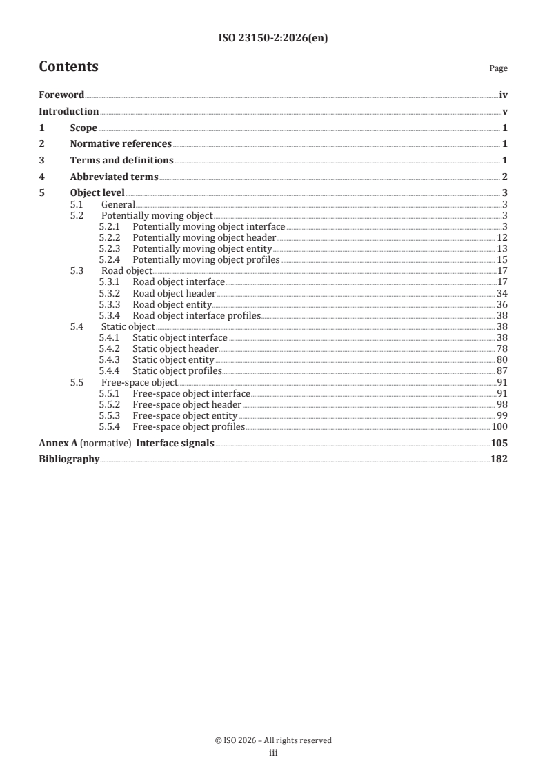
The document is organized into the core front matter and five main clauses:
| Clause or annex | What it covers |
|---|---|
| Clause 1 | Scope |
| Clause 2 | Normative references |
| Clause 3 | Terms and definitions |
| Clause 4 | Abbreviated terms |
| Clause 5 | Object level, including the four interface families and their profiles |
| Annex A | Normative interface signals |
| Bibliography | Background references |
Clause 5 is split by interface family: potentially moving object, road object, static object and free-space object. Each family has its own interface, header, entity and profile subsections, so a reader can find the signals and profile rules for one object type without reading the whole document.
What are the key requirements of ISO 23150-2:2026?
ISO 23150-2:2026 builds every object-level interface on the generic object-level rules of ISO 23150-1:2026. In practice, that means an implementer starts from the shared interface model and then adds the signals for a specific object family.
Shared interface structure
Clause 5.1 says the object-level interfaces shall be based on the generic object level interface in ISO 23150-1:2026, 7.2. That matters because all four object families reuse the same logical structure for versioning, timestamps, sensor identification and data qualification.
Annex A supports this structure by listing the interface signals used in the document. For integration work, this is the place where a team checks which signals are mandatory, optional or conditional for a given interface.
Potentially moving object interface
Clause 5.2.1 defines the potentially moving object interface. It includes interface versioning, sensor ID, prediction timestamp, data qualifier and object count, then adds object content such as existence probability, object ID, age, observation status, measurement status and track quality.
The interface also carries motion and pose information such as position, orientation, bounding box extent, velocity, acceleration, rotation rate and movement status. In practice, that is the data needed to describe nearby vehicles, pedestrians or other moving participants in a form the fusion unit can use directly.
Clause 5.2.1 also extends the object description with profiles for motion type and motion state vector, plus specific groups for lights, persons, person body parts, eye state, actions and accessories. It also includes lane association and sensor-specific data such as entity radar cross section and entity lidar reflectivity, which is important when the same object must be interpreted by different sensor technologies.
Road object interface
Clause 5.3.1 defines the road object interface for road surface, road markings and road boundaries. These objects can be described with polynomials and polylines, and the document uses connection grouping to show how road marking contours relate to one another.
This matters because road geometry is not just a single shape. The interface separates the contour representation from supporting information such as road type, road property type, road surface condition classification, road marking type, road boundary type and lane association.
Clause 5.3.1 also covers richer road-related content such as traffic sign classifications, sign values, sign text, colour tone, guiding graphs, object references and occlusions. For implementation, that means a road object can describe both the physical marking or boundary and the road-related information attached to it.
Static object interface
Clause 5.4.1 defines the static object interface for general landmarks, traffic signs, traffic sign boards and traffic lights. It shares the same common header structure and then adds object-specific information such as classifications, position, orientation and bounding boxes.
The traffic sign board content is especially detailed. Clause 5.4.3 shows that a board can carry regions, guiding graphs, texts, icons or symbols, object references and occlusions, with local coordinate information for board regions and guiding graph elements. In practice, this is the interface a system uses when the visual meaning of a sign board has to be preserved, not just the sign text itself.
Clause 5.4.4 adds profiles for traffic supplementary signs and detection references for 3D detections. That helps systems represent stacked or related sign information in a structured way.
Free-space object interface
Clause 5.5.1 defines the free-space object interface for the open area around the vehicle. It includes free-space type, free-space shapes, road surface-related information, limitation geometry, limitation classification and clearance.
This interface is important when the system must tell the fusion unit what is drivable or blocked, not only where objects are. The document uses shape type and limitation geometry type to describe the boundary of free-space, and it adds limitation moving probability and object references where relevant.
Clause 5.5.4.1 gives the profile for shape type in free-space objects. In practice, this lets a sensor or sensor cluster represent road edges, holes, static obstacles, maximum-range shapes and limited free-space regions in a consistent logical form.
What terms does ISO 23150-2:2026 define?
ISO 23150-2:2026 uses the terms and definitions from ISO 23150-1:2026. Its abbreviated terms section introduces the short forms used across the interface tables.
- AD - automated driving - the vehicle function domain covered by the standard.
- ECU - electronic control unit - the control hardware that may process or exchange the interface data.
- OLI - object level interface - the shared logical layer for object-based exchange.
- PMOI - potentially moving object interface - the interface for objects that may move, such as vehicles or persons.
- RDOI - road object interface - the interface for road surface, road markings and road boundaries.
- SOI - static object interface - the interface for fixed scene objects such as signs and traffic lights.
- FSOI - free-space object interface - the interface for free-space and limitation information.
- VRO - value representation optimisation - the profile mechanism used to select an efficient representation of a value.
Who uses ISO 23150-2:2026?
ISO 23150-2:2026 is used by engineers and system architects working on vehicle environmental perception, sensor clusters and data fusion units. It is also relevant to teams integrating cameras, radar and lidar into automated driving functions.
Quality managers and buyers use it to check whether a sensor or fusion interface matches the expected object-level data model. Validation and verification teams use it when they need to confirm that classifications, positions, shapes and confidence-related fields are represented consistently.
What changed in ISO 23150-2:2026 from the previous edition?
This first edition of ISO 23150-2:2026 cancels and replaces ISO 23150:2023, and the foreword says it has been technically revised.
The main changes listed are:
- reorganisation of the document structure
- use of the generic interfaces, generic signals, generic profiles and terms and definitions from ISO 23150-1 as the basis
- separation of specific interface collections into individual documents
- inclusion in this part of the specific collection of all object-level interfaces
Which standards are used with ISO 23150-2:2026?
| Standard | Contribution in this document |
|---|---|
| ISO 23150-1:2026 | Provides the general information and principles, the generic object level interface, the level-independent profiles, and the shared terms, definitions and generic signals used here |
| ISO 23150-20 | Provides supportive sensor interfaces and sensor input information interfaces, which the introduction identifies as additional logical interfaces |
| ISO 23150-11, ISO 23150-12, ISO 23150-13, ISO 23150-14, ISO 23150-15 | Technology-specific parts of the ISO 23150 series that cover feature level, advanced detection level and detection level interfaces |
What does the ISO 23150-2:2026 document contain?
ISO 23150-2:2026 contains detailed signal tables for each object family, with headers, entity signals and profile-specific groups. The tables show which signals are mandatory, optional or conditional, and they reuse named signals from ISO 23150-1:2026.
The document also includes explanatory figures for common implementation cases such as potentially moving objects, road-marking contours, traffic sign boards, traffic lights and free-space limitations. These figures help readers see how the logical fields map to real scene structures.
Annex A is normative and lists the interface signals in full, including header signals and object-level entity-specific signals. For implementation, that annex is the main reference for signal names and signal grouping.
Relations
- Effective Date
- 28-Oct-2023
Get Certified
Connect with accredited certification bodies for this standard

TÜV Rheinland
TÜV Rheinland is a leading international provider of technical services.

TÜV SÜD
TÜV SÜD is a trusted partner of choice for safety, security and sustainability solutions.

DEKRA Certification Inc.
DEKRA US certification services.
Sponsored listings
Frequently Asked Questions
ISO 23150-2:2026 is a standard published by the International Organization for Standardization (ISO). Its full title is "Road vehicles — Logical interface between sensors and data fusion unit for automated driving functions — Part 2: Object level interfaces". This standard covers: This document is applicable to road vehicles with automated driving functions and specifies the interfaces at the object level: potentially moving object interface; road object interface; static object interface; free-space object interface. This document does not provide electrical and mechanical interface specifications. Raw data interfaces are also excluded.
This document is applicable to road vehicles with automated driving functions and specifies the interfaces at the object level: potentially moving object interface; road object interface; static object interface; free-space object interface. This document does not provide electrical and mechanical interface specifications. Raw data interfaces are also excluded.
ISO 23150-2:2026 is classified under the following ICS (International Classification for Standards) categories: 43.040.15 - Car informatics. On board computer systems. The ICS classification helps identify the subject area and facilitates finding related standards.
ISO 23150-2:2026 has the following relationships with other standards: It is inter standard links to ISO 23150:2023. Understanding these relationships helps ensure you are using the most current and applicable version of the standard.
ISO 23150-2:2026 is available in PDF format for immediate download after purchase. The document can be added to your cart and obtained through the secure checkout process. Digital delivery ensures instant access to the complete standard document.
Standards Content (Sample)
International
Standard
ISO 23150-2
First edition
Road vehicles — Logical interface
2026-06
between sensors and data fusion
unit for automated driving
functions —
Part 2:
Object level interfaces
Véhicules routiers — Interface logique entre capteurs et unité de
fusion de données pour les fonctions de conduite automatisée —
Partie 2: Interfaces de niveau objet
Reference number
© ISO 2026
All rights reserved. Unless otherwise specified, or required in the context of its implementation, no part of this publication may
be reproduced or utilized otherwise in any form or by any means, electronic or mechanical, including photocopying, or posting on
the internet or an intranet, without prior written permission. Permission can be requested from either ISO at the address below
or ISO’s member body in the country of the requester.
ISO copyright office
CP 401 • Ch. de Blandonnet 8
CH-1214 Vernier, Geneva
Phone: +41 22 749 01 11
Email: copyright@iso.org
Website: www.iso.org
Published in Switzerland
ii
Contents Page
Foreword .iv
Introduction .v
1 Scope . 1
2 Normative references . 1
3 Terms and definitions . 1
4 Abbreviated terms . 2
5 Object level . 3
5.1 General .3
5.2 Potentially moving object .3
5.2.1 Potentially moving object interface .3
5.2.2 Potentially moving object header . 12
5.2.3 Potentially moving object entity . 13
5.2.4 Potentially moving object profiles . 15
5.3 Road object . .17
5.3.1 Road object interface .17
5.3.2 Road object header . 34
5.3.3 Road object entity. 36
5.3.4 Road object interface profiles . 38
5.4 Static object . 38
5.4.1 Static object interface . 38
5.4.2 Static object header . 78
5.4.3 Static object entity . 80
5.4.4 Static object profiles . . 87
5.5 Free-space object . . .91
5.5.1 Free-space object interface .91
5.5.2 Free-space object header . 98
5.5.3 Free-space object entity . 99
5.5.4 Free-space object profiles . 100
Annex A (normative) Interface signals .105
Bibliography .182
iii
Foreword
ISO (the International Organization for Standardization) is a worldwide federation of national standards
bodies (ISO member bodies). The work of preparing International Standards is normally carried out through
ISO technical committees. Each member body interested in a subject for which a technical committee
has been established has the right to be represented on that committee. International organizations,
governmental and non-governmental, in liaison with ISO, also take part in the work. ISO collaborates closely
with the International Electrotechnical Commission (IEC) on all matters of electrotechnical standardization.
The procedures used to develop this document and those intended for its further maintenance are described
in the ISO/IEC Directives, Part 1. In particular, the different approval criteria needed for the different types
of ISO document should be noted. This document was drafted in accordance with the editorial rules of the
ISO/IEC Directives, Part 2 (see http://www.iso.org/directives).
ISO draws attention to the possibility that the implementation of this document may involve the use of (a)
patent(s). ISO takes no position concerning the evidence, validity or applicability of any claimed patent
rights in respect thereof. As of the date of publication of this document, ISO had not received notice of (a)
patent(s) which may be required to implement this document. However, implementers are cautioned that
this may not represent the latest information, which may be obtained from the patent database available at
http://www.iso.org/patents. ISO shall not be held responsible for identifying any or all such patent rights.
Any trade name used in this document is information given for the convenience of users and does not
constitute an endorsement. For an explanation of the voluntary nature of standards, the meaning of ISO
specific terms and expressions related to conformity assessment, as well as information about ISO's
adherence to the World Trade Organization (WTO) principles in the Technical Barriers to Trade (TBT), see
http://www.iso.org/iso/foreword.html.
This document was prepared by Technical Committee ISO/TC 22, Road vehicles, Subcommittee SC 31, Data
communication.
[1] [2] [3]
This first edition of ISO 23150-2, together with ISO 23150-1 , ISO 23150-11 , ISO 23150-12 , ISO 23150-13
[4] [5] [6] [7]
, ISO 23150-14 , ISO 23150-15 and ISO 23150-20 , cancels and replaces ISO 23150:2023, which has
been technically revised.
The main changes are as follows:
— reorganisation of the document structure; use of generic interfaces, generic signals, generic profiles and
[1]
terms and definitions defined in ISO 23150-1 as a basis for this document;
— specific collection of interfaces in separated documents; in this document specific collection of all
interfaces on object level.
A list of all parts in the ISO 23150 series can be found on the ISO website.
Any feedback or questions on this document should be directed to the user’s national standards body. A
complete listing of these bodies can be found at www.iso.org/members.html.
iv
Introduction
Vehicle environmental perception sensors (single sensor or sensor cluster) provide logical interfaces
according to the ISO 23150 series to the fusion unit or automated driving functions. The fusion unit
generates a surround model and interprets the scene around the vehicle based on the sensor data. Interfaces
are defined on different levels and described in a modular and semantic representation. The interfaces
on feature level, advanced detection level and detection level are technology specific and differ by each
technology.
Figure 1 shows the schematic and contextual relationships between the documents relating to logical
interfaces of the ISO 23150 series.
Key
scope of this document
Figure 1 — Relationship of the ISO 23150 series
This document specifies the object level interfaces. Object interfaces such as the "potentially -moving -object
interface" (5.2.1), the "road object interface" (5.3.1), the "static object interface" (5.4.1) and the "free-space
object interface" (5.5.1) are part of the object level. These interfaces are based on the generic specifications
[1]
of the object level interface in the ISO 23150-1 , which are supplied by single sensors or sensor clusters.
This document references generic specifications of signals of the header and the generic interface levels.
A sensor or sensor cluster may also implement (provide or receive) logical interfaces:
— on feature, advanced detection or detection level (see technology specific parts of the ISO 23150 series);
— for additional interfaces as supportive sensor interfaces and sensor input information interfaces (see
[7]
ISO 23150-20 ).
This document is not intended to replace the logical interface specifications of other documents in the
ISO 23150 series.
[1]
This document is based on the generic specifications in ISO 23150-1 as shown in Figure 2:
— generic object level interface;
— general level-independent profiles.
v
Key
scope of this document
Figure 2 — Interfaces in the scope of this document and the related interfaces of the ISO 23150
series
vi
International Standard ISO 23150-2:2026(en)
Road vehicles — Logical interface between sensors and data
fusion unit for automated driving functions —
Part 2:
Object level interfaces
1 Scope
This document is applicable to road vehicles with automated driving functions and specifies the interfaces
at the object level:
— potentially moving object interface;
— road object interface;
— static object interface;
— free-space object interface.
This document does not provide electrical and mechanical interface specifications. Raw data interfaces are
also excluded.
2 Normative references
The following documents are referred to in the text in such a way that some or all of their content constitutes
requirements of this document. For dated references, only the edition cited applies. For undated references,
the latest edition of the referenced document (including any amendments) applies.
ISO 23150-1, Road vehicles — Logical interface between sensors and data fusion unit for automated driving
functions — Part 1: General information and principles
ISO 23150-1:2026, Road vehicles — Logical interface between sensors and data fusion unit for automated
driving functions — Part 1: General information and principles
3 Terms and definitions
For the purposes of this document, the terms and definitions given in ISO 23150-1 apply.
ISO and IEC maintain terminology databases for use in standardization at the following addresses:
— ISO Online browsing platform: available at https:// www .iso .org/ obp
— IEC Electropedia: available at https:// www .electropedia .org/
4 Abbreviated terms
A2I assign to interface
AD automated driving
ADLI advanced detection level interface
AER alternative entity representation
C conditional
D dimensional
DE default enumerators
DLI detection level interface
ECU electronic control unit
EES extended enumeration signal
EM error model
FLI feature level interface
FSOI free-space object interface
ID identifier
IQR interquartile range
IR infrared
IRI international roughness index
IV implicit value
LL list length
LSG logical signal group
M mandatory
O optional
OLI object level interface
PMOI potentially moving object interface
RDOI road object interface
RL requirement level
SII sensor input interface
SOI static object interface
SSI supportive sensor interface
UTL unrolling tuple list
VRO value representation optimisation
5 Object level
5.1 General
The generic specification of the object level interfaces is defined in ISO 23150-1:2026, Clause 7. The object
level interfaces shall be based on the generic object level interface as specified in ISO 23150-1:2026, 7.2.
On object level the following interfaces are available:
— potentially moving object interface (5.2.1);
— road object interface (5.3.1);
— static object interface (5.4.1);
— free-space object interface (5.5.1).
5.2 Potentially moving object
5.2.1 Potentially moving object interface
The potentially moving object interface (PMOI) contains the list of objects that could potentially move and
are relevant for driving situations. This includes all objects that currently move, have moved (see Figure 3)
and that are not definitely static three-dimensional structures. Table 1 defines the general structure of the
potentially moving object interface.
Table 1 — Potentially moving object interface structure
Structure Multiplicity Option
Potentially moving object header (5.2.2) 1
Potentially moving objects Multiple Size type:
dynamic/fixed
The logical structure of the PMOI shall be implemented in accordance with the interface definition specified
in Table 2, the signals as defined in Annex A and ISO 23150-1:2026, Annex A. Furthermore, the generic
profiles as defined in 5.2.4 and in ISO 23150-1:2026 as well as the signal options defined in ISO 23150-1:2026,
Annex B shall also be considered. The object interface defines sets of signals for more detailed potentially
moving object types (for example, lights, persons).
Table 2 — Potentially moving object interface
RL LSG RL signal
LSG Signal Option
M/C/O M/C/O
Information: M Interface version ID {major, M Profile: Uniqueness of
interface minor, patch} (ISO 23150-1:2026, interface versioning
A.1.2) (ISO 23150-1:2026,
6.5.1)
Interface ID (ISO 23150-1:2026, O Profile: Uniqueness of
A.1.3) interface versioning
(ISO 23150-1:2026,
6.5.1)
Number of valid serving sensors M Profile: Uniqueness of
(ISO 23150-1:2026, A.1.4) interface versioning
(ISO 23150-1:2026,
6.5.1)
Optimise LL (ISO
23150-1:2026, B.1.2)
Alternative UTL (ISO
23150-1:2026, B.1.7)
Key: Sensor ID (ISO
23150-1:2026, A.1.5)
Size type: dynamic/fixed
Size #: Number of valid serving sensors (ISO 23150-1:2026, A.1.4)
Sensor ID (ISO 23150-1:2026, M Profile: Uniqueness of
A.1.5) interface versioning
(ISO 23150-1:2026,
6.5.1)
Alternative VRO (ISO
23150-1:2026, B.1.4)
Time stamp – prediction (ISO M
23150-1:2026, A.1.6.1)
Cycle counter (ISO 23150- O Redundancy (ISO
1:2026, A.1.7.1) 23150-1:2026, B.1.3)
Signal: Time stamp –
prediction (ISO 23150-
1:2026, A.1.6.1)
Interface cycle time (ISO 23150- O
1:2026, A.1.8)
Interface cycle time – variation O
(ISO 23150-1:2026, A.1.9)
Data qualifier (ISO 23150- M Optimise DE (ISO
1:2026, A.1.10) 23150-1:2026, B.1.8)
Optimise EES (ISO
23150-1:2026, B.1.9)
Motion type (A.1.2) M Profile: Motion type
(5.2.4.1)
Optimise DE (ISO
23150-1:2026, B.1.8)
Optimise EES (ISO
23150-1:2026, B.1.9)
Potentially moving objects
TTabablele 2 2 ((ccoonnttiinnueuedd))
RL LSG RL signal
LSG Signal Option
M/C/O M/C/O
Potentially M Recognised objects – capabili- O
moving objects ty – potentially moving objects
information (A.1.3.1)
Recognised objects – status O Redundancy (ISO
– potentially moving objects 23150-1:2026, B.1.3)
(A.1.4.1) Signal: Recognised
objects – capability
– potentially moving
objects (A.1.3.1)
Optimise DE (ISO
23150-1:2026, B.1.8)
Optimise EES (ISO
23150-1:2026, B.1.9)
Number of valid objects – poten- M Optimise LL (ISO
tially moving objects (A.1.5.1) 23150-1:2026, B.1.2)
Size type: dynamic/fixed
Size #: Number of valid objects – potentially moving objects (A.1.5.1)
↪ Potentially M Existence probability – ob- M
moving object ject level (ISO 23150-1:2026,
status A.3.2)
Object ID (ISO 23150-1:2026, M Alternative A2I (ISO
A.3.3) 23150-1:2026, B.3.3)
Object grouping ID (ISO O
23150-1:2026, A.3.4)
Age (ISO 23150-1:2026, M Profile: Observations
A.2.22) (ISO 23150-1:2026,
6.5.8)
Number of valid observa- O Profile: Observations
tions (ISO 23150-1:2026, (ISO 23150-1:2026,
A.2.23) 6.5.8)
Optimise LL (ISO
23150-1:2026, B.1.2)
Alternative UTL (ISO
23150-1:2026, B.1.7)
Key: Time stamp
reference (ISO 23150-
1:2026, A.2.24)
Size type: dynamic/fixed
Size #: Number of valid observations (ISO 23150-1:2026, A.2.23)
Time stamp reference M Profile: Observations
(ISO 23150-1:2026, (ISO 23150-1:2026,
A.2.24) 6.5.8)
Alternative VRO (ISO
23150-1:2026, B.1.4)
TTabablele 2 2 ((ccoonnttiinnueuedd))
RL LSG RL signal
LSG Signal Option
M/C/O M/C/O
Observation status (ISO M Profile: Observations
23150-1:2026, A.2.25) (ISO 23150-1:2026,
6.5.8)
Redundancy (ISO
23150-1:2026, B.1.3)
Signal: Object ID (ISO
23150-1:2026, A.3.3),
Time stamp – pre-
diction (ISO 23150-
1:2026, A.1.6.1)
Optimise DE (ISO
23150-1:2026, B.1.8)
Optimise EES (ISO
23150-1:2026, B.1.9)
Track quality (ISO 23150- O
1:2026, A.3.5)
Measurement status (ISO M Profile: Measurement
23150-1:2026, A.2.68) status (ISO 23150-
1:2026, 6.5.18)
Optimise DE (ISO
23150-1:2026, B.1.8)
Optimise EES (ISO
23150-1:2026, B.1.9)
↪ Potentially M Tracking motion model O Optimise DE (ISO
moving object (A.2.2) 23150-1:2026, B.1.8)
information
Optimise EES (ISO
23150-1:2026, B.1.9)
Number of valid recognition M Profile: Recognition
classifications (ISO 23150- classification type (ISO
1:2026, A.2.61) 23150-1:2026, 6.5.15)
Optimise LL (ISO
23150-1:2026, B.1.2)
Alternative UTL (ISO
23150-1:2026, B.1.7)
Key: Recognition
classification type (ISO
23150-1:2026, A.2.62)
Size type: dynamic/fixed
Size #: Number of valid recognition classifications (ISO 23150-1:2026,
A.2.61)
Recognition classification M Profile: Recognition
type (ISO 23150-1:2026, classification type (ISO
A.2.62) 23150-1:2026, 6.5.15)
Alternative VRO (ISO
23150-1:2026, B.1.4)
Optimise DE (ISO
23150-1:2026, B.1.8)
Optimise EES (ISO
23150-1:2026, B.1.9)
Recognition classification M Profile: Recognition
type – confidence (ISO classification type (ISO
23150-1:2026, A.2.63) 23150-1:2026, 6.5.15)
TTabablele 2 2 ((ccoonnttiinnueuedd))
RL LSG RL signal
LSG Signal Option
M/C/O M/C/O
Road level (A.2.3) O Redundancy (ISO
23150-1:2026, B.1.3)
Signal: {z} of Position
{x, y, z} (ISO 23150-
1:2026, A.2.43)
Optimise DE (ISO
23150-1:2026, B.1.8)
Optimise EES (ISO
23150-1:2026, B.1.9)
↪ Potentially M Position {x, y, z} (ISO 23150- {M, M, O} Profile: Object pose
moving object 1:2026, A.2.43) (ISO 23150-1:2026,
position 7.5.3)
Profile: Motion state
vector (5.2.4.2)
Position {x, y, z} – error (ISO C Profile: Object pose
23150-1:2026, A.2.44) Analog: Position {x, y, (ISO 23150-1:2026,
z} (ISO 23150-1:2026, 7.5.3)
A.2.43)
Profile: Motion state
vector (5.2.4.2)
Implementation EM
(ISO 23150-1:2026,
B.4.2)
Orientation {yaw, pitch, roll} {C (ISO 23150-1:2026, Profile: Object pose
(ISO 23150-1:2026, A.3.22) B.2.2) (ISO 23150-1:2026,
Relevant: camera, O, 7.5.3)
O}
Profile: Motion state
vector (5.2.4.2)
Orientation {yaw, pitch, roll} O Profile: Object pose
– error (ISO 23150-1:2026, (ISO 23150-1:2026,
A.3.23) 7.5.3)
Profile: Motion state
vector (5.2.4.2)
Implementation EM
(ISO 23150-1:2026,
B.4.2)
Reference point {x, y, z} (ISO O Profile: Object pose
23150-1:2026, A.3.24) (ISO 23150-1:2026,
7.5.3)
Optimise DE (ISO
23150-1:2026, B.1.8)
Optimise EES (ISO
23150-1:2026, B.1.9)
↪ Potentially C (ISO 23150- Bounding box extent {length, C Profile: Object pose
moving object 1:2026, B.2.2) width, height} (ISO 23150- Analog: Position {x, y, (ISO 23150-1:2026,
bounding box Relevant: cam- 1:2026, A.3.25) z} (ISO 23150-1:2026, 7.5.3)
era A.2.43)
Bounding box extent {length, O Profile: Object pose
width, height} – error (ISO (ISO 23150-1:2026,
23150-1:2026, A.3.26) 7.5.3)
Implementation EM
(ISO 23150-1:2026,
B.4.2)
Clearance of the object O
{height} (A.2.4)
TTabablele 2 2 ((ccoonnttiinnueuedd))
RL LSG RL signal
LSG Signal Option
M/C/O M/C/O
Included geometric struc- O Optimise DE (ISO
tures (A.2.5) 23150-1:2026, B.1.8)
Optimise EES (ISO
23150-1:2026, B.1.9)
↪ Potentially M Velocity {x, y, z} (A.2.6) C Profile: Motion type
moving object Analog: Position {x, y, (5.2.4.1)
dynamics z} (ISO 23150-1:2026,
Profile: Motion state
A.2.43)
vector (5.2.4.2)
Velocity {x, y, z} – error O Profile: Motion type
(A.2.7) (5.2.4.1)
Profile: Motion state
vector (5.2.4.2)
Implementation EM
(ISO 23150-1:2026,
B.4.2)
Acceleration {x, y, z} (A.2.8) O Profile: Motion type
(5.2.4.1)
Acceleration {x, y, z} – error O Profile: Motion type
(A.2.9) (5.2.4.1)
Implementation EM
(ISO 23150-1:2026,
B.4.2)
Instantaneous centre of rota- C (ISO 23150-1:2026,
tion {x, y} (A.2.10) B.2.3)
Signal: Rotation rate
at instantaneous cen-
tre of rotation {yaw}
(A.2.12)
Instantaneous centre of rota- O Implementation EM
tion {x, y} – error (A.2.11) (ISO 23150-1:2026,
B.4.2)
Rotation rate at instantane- O Profile: Motion type
ous centre of rotation {yaw} (5.2.4.1)
(A.2.12)
Profile: Motion state
vector (5.2.4.2)
Rotation rate at instantane- O Profile: Motion type
ous centre of rotation {yaw} (5.2.4.1)
– error (A.2.13)
Profile: Motion state
vector (5.2.4.2)
Implementation EM
(ISO 23150-1:2026,
B.4.2)
Movement status (A.2.14) O Optimise DE (ISO
23150-1:2026, B.1.8)
Optimise EES (ISO
23150-1:2026, B.1.9)
TTabablele 2 2 ((ccoonnttiinnueuedd))
RL LSG RL signal
LSG Signal Option
M/C/O M/C/O
↪ Potentially C (ISO 23150- Number of valid lights M Optimise LL (ISO
moving object’s 1:2026, B.2.2) (A.2.15) 23150-1:2026, B.1.2)
lights Relevant: cam-
Alternative UTL (ISO
era
23150-1:2026, B.1.7)
Key: Light type
(A.2.16)
Size type: dynamic/fixed
Size #: Number of valid lights (A.2.15)
Light type (A.2.16) M Alternative VRO (ISO
23150-1:2026, B.1.4)
Optimise DE (ISO
23150-1:2026, B.1.8)
Optimise EES (ISO
23150-1:2026, B.1.9)
Light status (A.2.17) M Optimise DE (ISO
23150-1:2026, B.1.8)
Optimise EES (ISO
23150-1:2026, B.1.9)
↪ Potentially O Number of valid persons M Optimise LL (ISO
moving object: (A.2.18) 23150-1:2026, B.1.2)
persons
Size type: dynamic/fixed
Size #: Number of valid persons (A.2.18)
Number of valid person M Optimise LL (ISO
type roles (A.2.19) 23150-1:2026, B.1.2)
Alternative UTL (ISO
23150-1:2026, B.1.7)
Key: Person type role
(A.2.20)
Size type: dynamic/fixed
Size #: Number of valid person type roles (A.2.19)
Person type role M Alternative VRO (ISO
(A.2.20) 23150-1:2026, B.1.4)
Optimise DE (ISO
23150-1:2026, B.1.8)
Optimise EES (ISO
23150-1:2026, B.1.9)
Person type role – M
confidence (A.2.21)
Number of valid person O Optimise LL (ISO
gestures (A.2.22) 23150-1:2026, B.1.2)
Alternative UTL (ISO
23150-1:2026, B.1.7)
Key: Person gesture in-
dication type (A.2.23)
TTabablele 2 2 ((ccoonnttiinnueuedd))
RL LSG RL signal
LSG Signal Option
M/C/O M/C/O
Size type: dynamic/fixed
Size #: Number of valid person gestures (A.2.22)
Person gesture indica- M Alternative VRO (ISO
tion type (A.2.23) 23150-1:2026, B.1.4)
Optimise DE (ISO
23150-1:2026, B.1.8)
Optimise EES (ISO
23150-1:2026, B.1.9)
Person gesture indica- O
tion type – confidence
(A.2.24)
Number of valid person’s M Optimise LL (ISO
body part poses (A.2.25) 23150-1:2026, B.1.2)
Alternative UTL (ISO
23150-1:2026, B.1.7)
Key: Person body part
(A.2.26)
Size type: dynamic/fixed
Size #: Number of valid person’s body part poses (A.2.25)
Person body part M Alternative VRO (ISO
(A.2.26) 23150-1:2026, B.1.4)
Optimise DE (ISO
23150-1:2026, B.1.8)
Optimise EES (ISO
23150-1:2026, B.1.9)
Person body part ori- M
entation {yaw, pitch,
roll} (A.2.27)
Person body part ori- O Implementation EM
entation {yaw, pitch, (ISO 23150-1:2026,
roll} – error (A.2.28) B.4.2)
Person body part ori- O
gin {x, y, z} (A.2.29)
Person body part O Implementation EM
origin {x, y, z} – error (ISO 23150-1:2026,
(A.2.30) B.4.2)
TTabablele 2 2 ((ccoonnttiinnueuedd))
RL LSG RL signal
LSG Signal Option
M/C/O M/C/O
Eye state (A.2.31) O Optimise DE (ISO
23150-1:2026, B.1.8)
Optimise EES (ISO
23150-1:2026, B.1.9)
Eye state – confidence O
(A.2.32)
Ego vehicle fixation time O
(A.2.33)
Ego vehicle fixation time O Implementation EM
– error (A.2.34) (ISO 23150-1:2026,
B.4.2)
Action type (A.2.35) O Optimise DE (ISO
23150-1:2026, B.1.8)
Optimise EES (ISO
23150-1:2026, B.1.9)
Action type – confidence O
(A.2.36)
Number of valid person O Optimise LL (ISO
accessories (A.2.37) 23150-1:2026, B.1.2)
Alternative UTL (ISO
23150-1:2026, B.1.7)
Key: Person accesso-
ry classification type
(A.2.38)
Size type: dynamic/fixed
Size #: Number of valid person accessories (A.2.37)
Person accessory M Alternative VRO (ISO
classification type 23150-1:2026, B.1.4)
(A.2.38)
Optimise DE (ISO
23150-1:2026, B.1.8)
Optimise EES (ISO
23150-1:2026, B.1.9)
Person accessory O
classification type –
confidence (A.2.39)
Accessory connec- O Optimise DE (ISO
tion to person type 23150-1:2026, B.1.8)
(A.2.40)
Optimise EES (ISO
23150-1:2026, B.1.9)
Included geometric O Optimise DE (ISO
structure of accessory 23150-1:2026, B.1.8)
(A.2.41)
Optimise EES (ISO
23150-1:2026, B.1.9)
↪ Lane related O Object lane association M Optimise DE (ISO
information (A.2.42) 23150-1:2026, B.1.8)
Optimise EES (ISO
23150-1:2026, B.1.9)
Angle between object edge O
and ego lane boundary {left
edge right lane, right edge
left lane} (A.2.43)
TTabablele 2 2 ((ccoonnttiinnueuedd))
RL LSG RL signal
LSG Signal Option
M/C/O M/C/O
Angle between object edge O Implementation EM
and ego lane boundary {left (ISO 23150-1:2026,
edge right lane, right edge B.4.2)
left lane} – error (A.2.44)
Object intruding ego lane O
{left, right} (A.2.45)
Object ego lane usage {left, O
right} (A.2.46)
↪ Motion relat- O Angular position {azimuth} O
ed information (A.2.47)
Angular velocity {azimuth} M
(A.2.48)
DEPRECATED: O DEPRECATED: Scale change M
↪ Camera sen- – object level (A.2.49)
sor technology
specific
↪ Radar sensor C (ISO 23150- Entity radar cross section M
technology 1:2026, B.2.2) (A.2.50)
specific Relevant: radar
↪ Lidar sensor C (ISO 23150- Entity lidar reflectivity M
technology 1:2026, B.2.2) (A.2.51)
specific Relevant: lidar
Key
1 vehicle
2 pedestrian
3 potentially moving object – classification unknown, for example, "Recognition classification type" (ISO 23150-
1:2026, A.2.62) with enumerator "PMOCT_Unknown"
Figure 3 — Example for potentially moving objects
5.2.2 Potentially moving object header
Table 3 defines the interface header for potentially moving objects and the changes due to the adaptation in
comparison to the "generic object level header" as specified in ISO 23150-1:2026, 7.3, which shall be used as
the interface header. The header of the PMOI specifies the list of valid potentially moving object entities (see
5.2.3).
Table 3 — Specific signal grouping: Potentially moving object header
Signal RL signal Option
Interface version ID {major, minor, patch} Mandatory Profile: Uniqueness of interface versioning
(ISO 23150-1:2026, A.1.2) (ISO 23150-1:2026, 6.5.1)
Interface ID (ISO 23150-1:2026, A.1.3) Optional Profile: Uniqueness of interface versioning
(ISO 23150-1:2026, 6.5.1)
Number of valid serving sensors (ISO 23150- Mandatory Profile: Uniqueness of interface versioning
1:2026, A.1.4) (ISO 23150-1:2026, 6.5.1)
Optimise LL (ISO 23150-1:2026, B.1.2)
Alternative UTL (ISO 23150-1:2026, B.1.7)
Key: Sensor ID (ISO 23150-1:2026, A.1.5)
↪ Sensor ID (ISO 23150-1:2026, A.1.5) Mandatory Profile: Uniqueness of interface versioning
(ISO 23150-1:2026, 6.5.1)
Alternative VRO (ISO 23150-1:2026, B.1.4)
Time stamp – prediction (ISO 23150-1:2026, Mandatory
A.1.6.1)
Cycle counter (ISO 23150-1:2026, A.1.7.1) Optional Redundancy (ISO 23150-1:2026, B.1.3)
Signal: Time stamp – measurement (ISO
23150-1:2026, A.1.6.2)
Interface cycle time (ISO 23150-1:2026, A.1.8) Optional
Interface cycle time – variation (ISO 23150- Optional
1:2026, A.1.9)
Data qualifier (ISO 23150-1:2026, A.1.10) Mandatory Optimise DE (ISO 23150-1:2026, B.1.8)
Optimise EES (ISO 23150-1:2026, B.1.9)
Motion type (A.1.2) Mandatory Profile: Motion type (5.2.4.1)
Optimise DE (ISO 23150-1:2026, B.1.8)
Optimise EES (ISO 23150-1:2026, B.1.9)
a
... Need of logical signal group (ISO 23150-
1:2026, B.3.4)
Profile: Vehicle coordinate system (ISO
23150-1:2026, 6.5.4)
Profile: Sensor pose (ISO 23150-1:2026, 6.5.5)
Profile: Calibration (ISO 23150-1:2026, 6.5.6)
Profile: Sensor cluster (ISO 23150-1:2026,
6.5.7)
Potentially moving objects
Recognised objects – capability – potentially Optional
moving objects (A.1.3.1)
Recognised objects – status – potentially Optional Redundancy (ISO 23150-1:2026, B.1.3)
moving objects (A.1.4.1) Signal: Recognised objects – capability – po-
tentially moving objects (A.1.3.1)
Optimise DE (ISO 23150-1:2026, B.1.8)
Optimise EES (ISO 23150-1:2026, B.1.9)
Number of valid objects – potentially moving Mandatory Optimise LL (ISO 23150-1:2026, B.1.2)
objects (A.1.5.1)
↪ Potentially moving object entities
a [8]
Further signals of "Need of logical signal group" (ISO 23150-1:2026 , B.3.4) profiles may be added to this header (see cell
options).
5.2.3 Potentially moving object entity
Each potentially moving object shall describe a recognised real-world object and consists of several LSGs.
Each object, which may move, even if it might have not moved yet since first recognition of the real-world
object, is an entity of potentially moving objects.
A potentially moving object is described by the following LSGs for potentially moving objects with attributes
for different parts (for example, vehicle, pedestrian).
— Status: the status describes general information of the tracked potentially moving object. This
information is based on history of the object tracking. Table 4 defines the signal grouping "Potentially
moving object entity status", which shall be used as the entity status. It defines this status LSG of the
potentially moving object and redefines the signal grouping "generic object level entity status", which
shall be as specified in ISO 23150-1:2026, 7.4.
— Information: the information describes properties such as the confidence of an object type.
— Position/ bounding box: the object pose of a potentially moving object is defined by "Profile: Object
pose" (ISO 23150-1:2026, 7.5.3). Due to recognition capabilities, small structures shall not be included
in the bounding box. The signal "Included geometric structures" (A.2.5) defines, what is included in the
bounding box. There is no signal defined to determine the minimal distance up to which an information,
relevant to the road user, is still recognizable.
— Dynamics: the dynamics describe the motion information of the tracked potentially moving object with
respect to the motion type defined by the signal "Motion type" (A.1.2) [see Profile: Motion type (5.2.4.1)].
— Lights: the lights describe the status of the tracked potentially moving object’s lights.
— Persons: the persons describe a recognised person type, its gestures and poses of the tracked persons if
the tracked potentially moving object may be a pedestrian or include persons (for example, the driver of
a vehicle).
— Lane related information: the lane related information describes the tracked potentially moving object
in relation with real-world lane boundaries.
— Motion related information: the motion related information describes additional motion information
of the tracked potentially moving object.
1)
— Camera sensor technology specific : the camera sensor technology specific data describe dynamic
information in the camera projection plane.
— Radar sensor technology specific: the radar sensor technology specific data describe different surface
and material properties of the potentially moving object with respect to the radar.
— Lidar sensor technology specific: the lidar sensor technology specific data describes different surface
and material properties of the potentially moving object with respect to the lidar (for example, reflection
strength of a surface).
Table 4 — Specific signal grouping: Potentially moving object entity status
Signal RL signal Option
Existence probability – object level (ISO Mandatory
23150-1:2026, A.3.2)
Object ID (ISO 23150-1:2026, A.3.3) Mandatory Alternative A2I (ISO 23150-1:2026, B.3.3)
Object grouping ID (ISO 23150-1:2026, A.3.4) Optional
Age (ISO 23150-1:2026, A.2.22) Mandatory Profile: Observations (ISO 23150-1:2026,
6.5.8)
Number of valid observations (ISO 23150- Optional Profile: Observations (ISO 23150-1:2026,
1:2026, A.2.23) 6.5.8)
Optimise LL (ISO 23150-1:2026, B.1.2)
Alternative UTL (ISO 23150-1:2026, B.1.7)
Key: Time stamp reference (ISO 23150-
1:2026, A.2.24)
1) The LSG is DEPRECATED.
TTabablele 4 4 ((ccoonnttiinnueuedd))
Signal RL signal Option
↪ Time stamp reference (ISO 23150-1:2026, Mandatory Profile: Observations (ISO 23150-1:2026,
A.2.24) 6.5.8)
Alternative VRO (ISO 23150-1:2026, B.1.4)
↪ Observation status (ISO 23150-1:2026, Mandatory Profile: Observations (ISO 23150-1:2026,
A.2.25) 6.5.8)
Redundancy (ISO 23150-1:2026, B.1.3)
Signal: Object ID (ISO 23150-1:2026, A.3.3),
Time stamp – prediction (ISO 23150-1:2026,
A.1.6.1)
Optimise DE (ISO 23150-1:2026, B.1.8)
Optimise EES (ISO 23150-1:2026, B.1.9)
Track quality (ISO 23150-1:2026, A.3.5) Optional
Measurement status (ISO 23150-1:2026, Mandatory Profile: Measurement status (ISO 23150-
A.2.68) 1:2026, 6.5.18)
Optimise DE (ISO 23150-1:2026, B.1.8)
Optimise EES (ISO 23150-1:2026, B.1.9)
Potentially moving objects or other object entities on object level may be linked together (for example, a
truck with a trailer or a construction site vehicle with a traffic sign at the rear of the vehicle) by using the
[8]
same signal’s "Object grouping ID"(ISO 23150-1:2026 , A.3.4) value in all connected objects.
5.2.4 Potentially moving object profiles
5.2.4.1 Profile: Motion type
The signal "Motion type" (A.1.2) defines the interpretation of the signal "Velocity {x, y, z}" (A.2.6)", "Velocity
{x, y, z} – error" (A.2.7), "Acceleration {x, y, z}" (A.2.8), "Acceleration {x, y, z} – error" (A.2.9), "Rotation rate
at instantaneous centre of rotation {yaw}" (A.2.12) and "Rotation rate at instantaneous centre of rotation
{yaw} – error" (A.2.13) values.
5.2.4.2 Profile: Motion state vector
A potentially moving object entity provides a motion state vector. The sensor may provide a full or enhanced
[8]
error model according to ISO 23150-1:2026 , B.4.1.3.5. For example, the motion state vector of the sensor
[8]
is provided together with an enhanced error model {"Position {x, y, z}" (ISO 23150-1:2026 , A.2.43),
[8]
"Velocity {x, y, z}" (A.2.6), "Orientation {yaw, pitch, roll}" (ISO 23150-1:2026 , A.3.21) and "Rotation rate at
instantaneous centre of rotation {yaw}" (A.2.12)}.
[8]
The resulting error model based on variances, covariances and cross-covariances (see ISO 23150-1:2026 ,
[8]
B.4.1.3.4 and ISO 23150-1:2026 , B.4.1.3.5) may provide a symmetric nD matrix:
(1)
where
[8]
"Position – error" corresponds to the signal "Position {x, y, z} – error" (ISO 23150-1:2026 ,
A.2.44);
"Velocity – error" corresponds to the signal "Velocity {x, y, z} – error" (A.2.7);
"Orientation – error" corresponds to the signal "Orientation {yaw, pitch, roll} – error" (ISO
[8]
23150-1:2026 , A.3.22);
"Rotation rate – error" corresponds to the signal "Rotation rate at instantaneous centre of
rotation {yaw} – error" (A.2.13).
[8]
In addition to existing error signals "Position {x, y, z} – error" (ISO 23150-1:2026 , A.2.44), "Velocity {x, y,
[8]
z} – error" (A.2.7), "Orientation {yaw, pitch, roll} – error" (ISO 23150-1:2026 , A.3.22) and "Rotation rate
at instantaneous centre of rotation {yaw} – error" (A.2.13); the additional signals may be provided as sets
of cross-covariances. All covariances of the motion state vector error model are symmetric and therefore
additional optimisation methods are applicable; this means only half of non-diagonal elements need to be
provided.
For example, the LSG "Potentially moving object motion state vector cross-covariances" may provide, for
example, "Position {x, y, z} x Velocity {x, y, z} – error", "Position {x, y, z} x Orientation {yaw, pitch, roll} – error".
The redundant symmetrical signals for the cross-covariances: "Velocity {x, y, z} x Position {x, y, z} – error",
"Orientation {yaw, pitch, roll} x Position {x, y, z} – error" may be skipped. Similar, the symmetric covariances
[8]
of the signals "Position {x, y, z} – error" (ISO 23150-1:2026 , A.2.44), "Velocity {x, y, z} – error" (A.2.7),
[8]
"Orientation {yaw, pitch, roll} – error" (ISO 23150-1:2026 , A.3.22) and "Rotation rate at instantaneous
centre of rotation {yaw} – error" (A.2.13) shall not transmit redundant values (see optimisation method
[8]
ISO 23150-1:2026 , B.1.6).
Table 5 provides a subset of the PMOI with the relevant signals for the motion state vector of this profile and
the additional signals in the LSG "Potentially moving object motion state vector cross-covariances".
Table 5 — Signal grouping: Exemplary motion state vector cross-covariances LSG
RL LSG RL signal
LSG Signal Option
M/C/O M/C/O
↪ Potentially M Position {x, y, z} (ISO 23150-1:2026, {M, M, O} Profile: Motion state
moving object A.2.43) vector (5.2.4.2)
position
Position {x, y, z} – error (ISO C Profile: Motion state
23150-1:2026, A.2.44) Analog: Position {x, vector (5.2.4.2)
y, z} (ISO 23150- …
1:2026, A.2.43)
Orientation {yaw, pitch, roll} (ISO {C (ISO 23150- Profile: Motion state
23150-1:2026, A.2.43), A.3.21) 1:2026, B.2.2) vector (5.2.4.2)
Relevant: camera,
O, O}
Orientation {yaw, pitch, roll} – O Profile: Motion state
error (ISO 23150-1:2026, A.3.22) vector (5.2.4.2)
…
… … …
↪ Potentially M Velocity {x, y, z} (A.2.6) C Profile: Motion state
moving object Analog: Position {x, vector (5.2.4.2)
dynamics y, z} (ISO 23150- …
1:2026, A.2.43)
Velocity {x, y, z} – error (A.2.7) O Profile: Motion state
vector (5.2.4.2)
…
Rotation rate at instantaneous cen- O Profile: Motion state
tre of rotation {yaw} (A.2.12) vector (5.2.4.2)
…
Rotation rate at instantaneous O Profile: Motion state
centre of rotation {yaw} – error vector (5.2.4.2)
(A.2.13) …
… … …
a [8]
The signal’s RL is optional by definition of ISO 23150-1:2026 , B.4.1.3.5 but for this profile (5.2.4.2) it should be defined as
mandatory during the system design phase so that at least one signal is mandatory in the LSG.
TTabablele 5 5 ((ccoonnttiinnueuedd))
RL LSG RL signal
LSG Signal Option
M/C/O M/C/O
a
↪ Potentially O Position {x, y, z} x Velocity {x, y, z} O Implementation EM
moving object – error (ISO 23150-1:2026,
motion state B.4.2)
vector cross-co-
Position {x, y, z} x Orientation {yaw, O Implementation EM
variances
pitch, roll} – error (ISO 23150-1:2026,
B.4.2)
Position {x, y, z} x Rotation rate at O Implementation EM
instantaneous centre of rotation (ISO 23150-1:2026,
{yaw} – error B.4.2)
Velocity {x, y, z} x Orientation {yaw, O Implementation EM
pitch, roll} – error (ISO 23150-1:2026,
B.4.2)
Velocity {x, y, z} x Rotation rate at O Implementation EM
instantaneous centre of rotation (ISO 23150-1:2026,
{yaw} – error B.4.2)
Orientation {yaw, pitch, roll} x Ro- O Implementation EM
tation rate at instantaneous centre (ISO 23150-1:2026,
of rotation {yaw} – error B.4.2)
a [8]
The signal’s RL is optional by definition of ISO 23150-1:2026 , B.4.1.3.5 but for this profile (5.2.4.2) it should be defined as
mandatory during the system design phase so that at least one signal is mandatory in the LSG.
Additionally, in most cases the description of the signals in planar space (XY-plane) is sufficient. Therefore,
below covariances may either be only 2D
...