

ISO 23150-1:2026
(Main)Road vehicles — Logical interface between sensors and data fusion unit for automated driving functions — Part 1: General information and principles
- Abstract
This document is applicable to road vehicles with automated driving functions. This document concerns the logical interface between vehicle environmental perception sensors and the fusion unit which generates a surround model and interprets the scene around the vehicle based on the sensor data. The interface is described in a modular and semantic representation and provides information on different abstraction levels based on sensor technology specific information. This document provides generic interface templates for different interface levels, supportive sensor interfaces and sensor input interfaces. This document does not provide electrical and mechanical interface specifications. Raw data interfaces are also excluded.
- Status
- Published
- Publication Date
- 28-Jun-2026
- Technical Committee
- ISO/TC 22/SC 31 - Data communication
- Current Stage
- 6060 - International Standard published
- Start Date
- 29-Jun-2026
- Due Date
- 22-Jan-2027
- Completion Date
- 29-Jun-2026

ISO 23150-1:2026 is an International Standard from ISO for road vehicles with automated driving functions. It specifies the logical interface between vehicle environmental perception sensors or sensor clusters and the fusion unit that builds a surround model and interprets the scene around the vehicle. The document is aimed at sensor suppliers, fusion-unit developers and system integrators who need a shared semantic interface, not an electrical, mechanical or raw-data interface.
What does ISO 23150-1:2026 specify?
ISO 23150-1:2026 defines the general principles and interface templates for the ISO 23150 series. It covers the logical interface description, the main interface levels, the shared signals and the rules for organizing them into usable interface definitions.
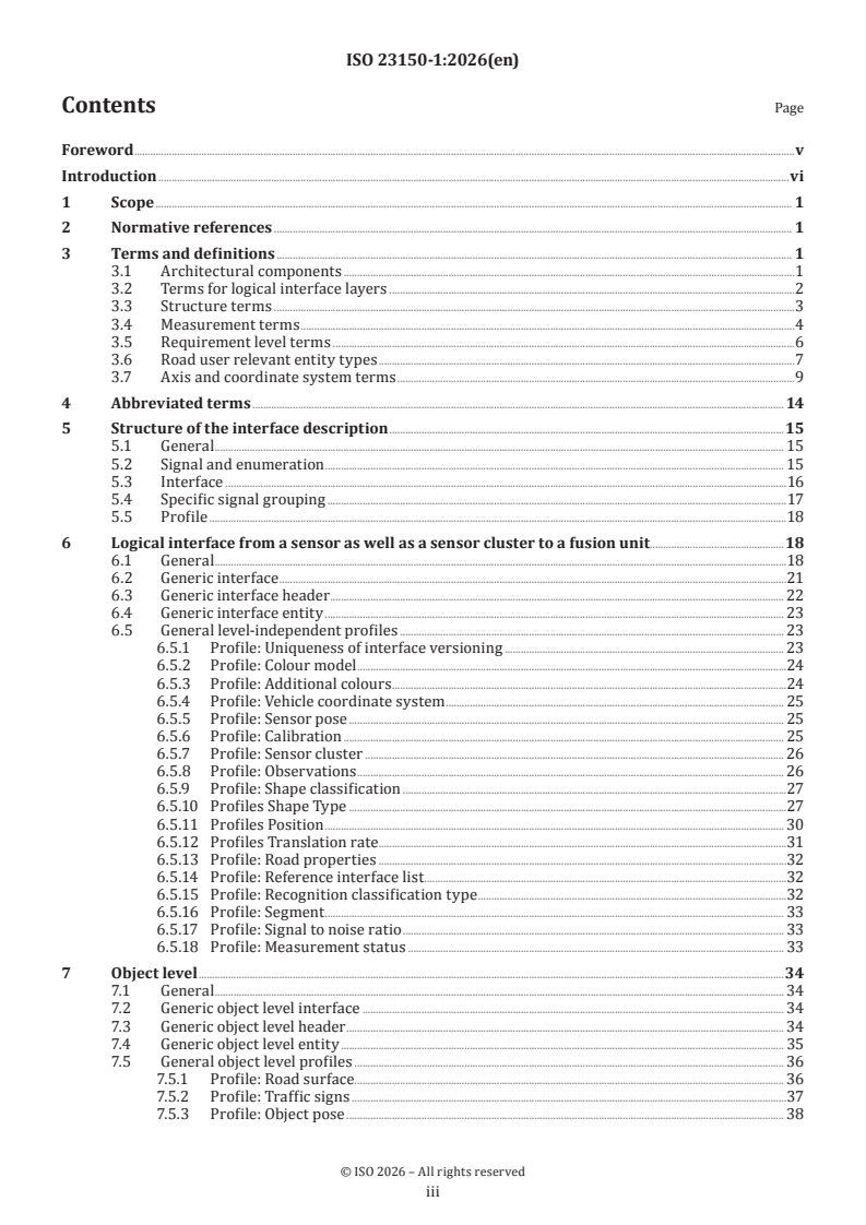
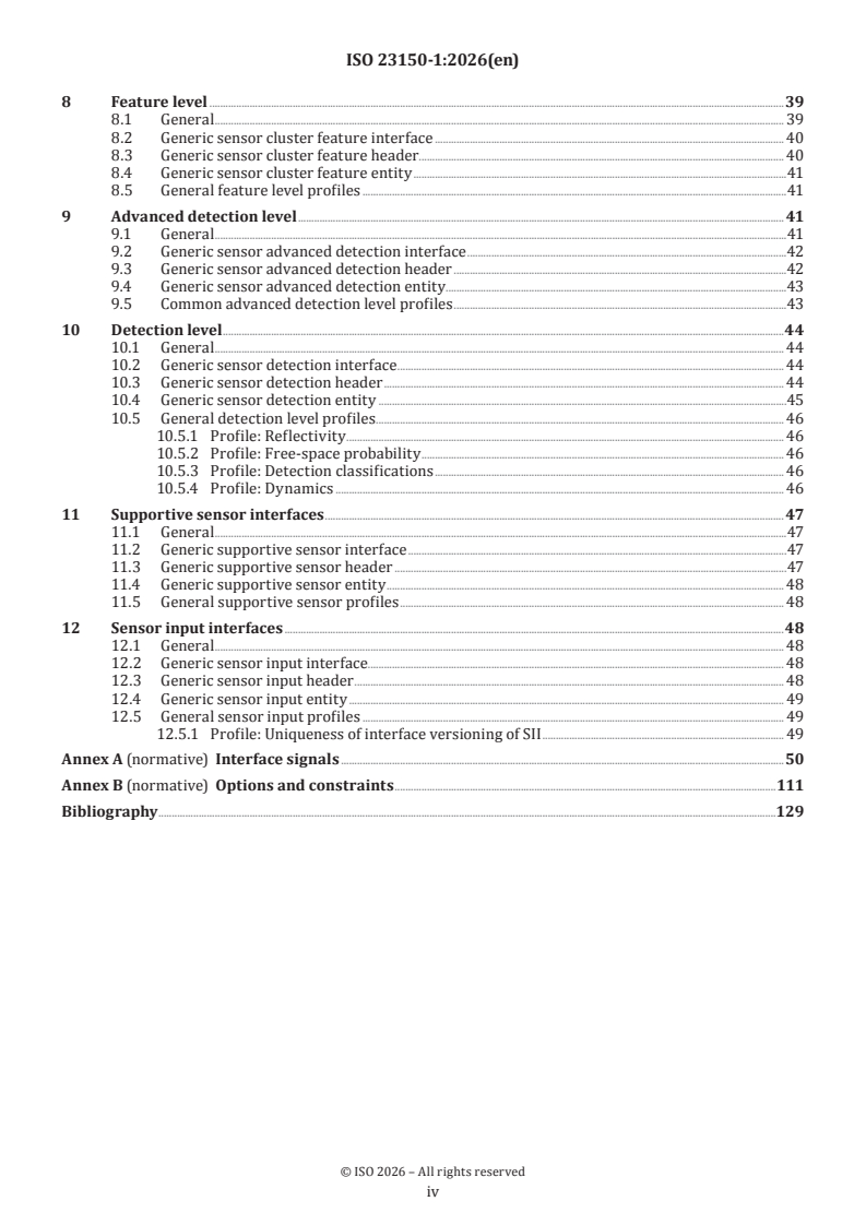
The document is organized around the core structure in Clause 5, the interface levels in Clauses 6 to 12, and two normative annexes that provide the signal and option definitions used across the series.
| Annex | What it covers |
|---|---|
| Annex A | Interface signals |
| Annex B | Options and constraints |
Clause 3 defines the terminology used throughout the series, Clause 4 lists abbreviated terms, and Clause 5 explains how signals, logical signal groups, interfaces and profiles fit together. Clauses 6 to 12 then apply that structure to object level, feature level, advanced detection level, detection level, supportive sensor interfaces and sensor input interfaces.
What are the key requirements of ISO 23150-1:2026?
ISO 23150-1:2026 sets up a modular logical interface model. The practical result is that implementers can describe sensor outputs in a common way, with clear signal names, requirement levels and profile rules, so that different sensors and fusion units can exchange semantically consistent information.
Clause 5 defines the interface structure
Clause 5 organizes each interface around signals, logical signal groups (LSGs), interfaces, specific signal groupings and profiles. Each signal carries one value, and enumerated signals use mandatory enumerators, with optional exemplary enumerator lists for system design.
In practice, this means interface designers need to treat signals as named data items with defined obligation status, not as ad hoc message fields. The document also makes signal names unique within the ISO 23150 series, which helps system integration and cross-document traceability.
The document separates interface levels by the kind of perception result
Clause 6 introduces four logical interface levels: object level, feature level, advanced detection level and detection level. It also defines supportive sensor interfaces and sensor input interfaces.
In practice, a sensor or sensor cluster shall provide at least one interface at object, feature, advanced detection or detection level. Object level and feature level are associated mainly with sensor clusters, while advanced detection and detection levels are associated mainly with sensors. This matters because different perception pipelines can expose different maturity of recognition, from raw detections up to tracked objects.
Headers carry timing, versioning and list-size information
The generic interface header includes time stamp information, and the level-specific headers add items such as cycle counter, message counter, interface versioning and interface identifiers where relevant. For entity lists, the headers also provide capability, status and number-of-valid-entities signals.
In practice, this is what lets a receiver know when data was measured or predicted, how many valid entities to expect, and whether a sensor or cluster can supply the requested interface type. That is important for fusion timing, diagnostics and interface compatibility checks.
Object level is for recognized objects in vehicle coordinates
Clause 7 defines the object level interface. Recognized objects are described in a vehicle coordinate system and are based on historical data and tracking over time. Each object has a unique Object ID, and related objects can be grouped with an Object grouping ID.
In practice, this level is used when a sensor cluster can already provide stable object descriptions such as potentially moving objects, road objects, static objects and free-space objects. The document also adds object-level profiles for items such as road surface, traffic signs and object pose, which helps a fusion unit combine object geometry with semantic context.
Feature, advanced detection and detection levels preserve links across perception stages
Clause 8 defines the feature level, Clause 9 the advanced detection level, and Clause 10 the detection level. Each of these levels has its own ID concept and existence probability, and each can reference related entities on other levels.
In practice, this is what enables fusion across sensors and across processing stages. Feature ID, Advanced detection ID and Detection ID let implementations link related entities without confusing one level with another, and the interface rules are written to prevent wrong link relations when IDs are reused over time.
Supportive sensor interfaces and sensor input interfaces serve different jobs
Clause 11 defines supportive sensor interfaces (SSI), which carry sensor-supporting information such as performance, health or other supportive data. Clause 12 defines sensor input interfaces (SII), which bring information and parametrisation to a sensor or sensor cluster through in-vehicle communication.
In practice, SSI data supports fusion quality and safety concepts, while SII data supports configuration and parameter exchange from electronic control units (ECUs). Clause 12 also adds versioning-related header signals, which matters when several ECUs may send input to the same sensor or sensor cluster.
Annex B defines optimisation and error-model options
Annex B gives the options and constraints for interface optimisation, including list length optimisation, redundancy optimisation, alternative value representation, alternative entity representation, implicit values, unrolling tuple-lists, default enumerators, extended enumeration signals and extended interfaces. It also covers cross-interface links and error model implementation.
In practice, Annex B is where designers decide how to reduce transmitted data while keeping the interface semantics intact. It also gives methods for expressing signal values and associated error values, including statistical approaches and covariance-based descriptions for tracking and fusion use.
What terms does ISO 23150-1:2026 define?
- Logical interface - The semantic boundary between a sensor or sensor cluster and the fusion unit; mechanical and electrical interfaces are outside this meaning.
- Fusion unit - The computing unit where sensor data and sensor cluster data are fused.
- Sensor cluster - A group of sensors of the same technology serving common logical interfaces.
- OLI - Object level interface; it provides recognized objects in a vehicle coordinate system.
- FLI - Feature level interface; it provides recognized features in a vehicle coordinate system.
- ADLI - Advanced detection level interface; it provides recognized advanced detections in a sensor coordinate system.
- DLI - Detection level interface; it provides recognized detections in a sensor coordinate system.
- SSI - Supportive sensor interface; it carries supportive information about the sensor or sensor cluster.
- SII - Sensor input interface; it carries information and parametrisation into a sensor or sensor cluster.
Who uses ISO 23150-1:2026?
ISO 23150-1:2026 is used by developers and integrators of automated driving functions for road vehicles. Typical users include sensor suppliers, sensor-cluster suppliers, fusion-unit developers, system suppliers and vehicle manufacturers.
It is also relevant to validation and verification teams, because the document structures what has to be exchanged, referenced and versioned across the perception chain. Quality managers and buyers can use it to check whether a proposed sensor interface fits an automated driving architecture that needs object, feature, advanced detection, detection, SSI or SII data.
What changed in ISO 23150-1:2026 from the previous edition?
ISO 23150-1:2026 is the first edition of Part 1. The foreword states that it is a structural revision of ISO 23150:2023 and that it mainly replaces Clauses 1 to 6 and Annex B.
The foreword also states that, together with ISO 23150-2, ISO 23150-11, ISO 23150-12, ISO 23150-13, ISO 23150-14, ISO 23150-15 and ISO 23150-20, this part cancels and replaces ISO 23150:2023.
Which standards are used with ISO 23150-1:2026?
ISO 23150-1:2026 is part of the ISO 23150 series and is used together with these companion parts:
- ISO 23150-2 - Object level interfaces
- ISO 23150-11 - Radar specific interfaces
- ISO 23150-12 - Lidar specific interfaces
- ISO 23150-13 - Camera specific interfaces
- ISO 23150-14 - Ultrasonic specific interfaces
- ISO 23150-15 - Microphone specific interfaces
- ISO 23150-20 - Supportive and sensor input interfaces
The document also draws on several referenced standards and vocabularies for terms and concepts, including ISO/IEC 2382 for information technology vocabulary, ISO/IEC Guide 99 and ISO 5725-1 for measurement concepts, ISO/IEC 11179-3 for requirement-level terms, ISO 8855 for vehicle coordinate and road-plane vocabulary, ISO 15007 for fixation, ISO 6707-1 and ISO 3864-1 for defined terms used in road and sign classifications, and ISO/SAE PAS 22736 for the use of the term feature.
What does the ISO 23150-1:2026 document contain?
ISO 23150-1:2026 contains the interface architecture, term definitions, abbreviated terms and the generic templates that the rest of the ISO 23150 series builds on. It also contains the signal catalog in Annex A and the optimisation, dependency and error-model rules in Annex B.
The document includes tables for interface headers, entity lists, requirement levels, enumerations and profiles, plus figures for the architecture and coordinate systems. These are used for interface design, implementation, integration testing and system validation.
Annex A is especially important because it lists the signals used across the series, including headers, entity-level signals, references between interface levels and the signals that support object, feature, advanced detection and detection representations. Annex B is the place to look for optimisation choices and for how to describe signal uncertainty, covariance and derived values when building the interface and its system design.
Relations
- Effective Date
- 28-Oct-2023
Get Certified
Connect with accredited certification bodies for this standard

TÜV Rheinland
TÜV Rheinland is a leading international provider of technical services.

TÜV SÜD
TÜV SÜD is a trusted partner of choice for safety, security and sustainability solutions.

DEKRA Certification Inc.
DEKRA US certification services.
Sponsored listings
Frequently Asked Questions
ISO 23150-1:2026 is a standard published by the International Organization for Standardization (ISO). Its full title is "Road vehicles — Logical interface between sensors and data fusion unit for automated driving functions — Part 1: General information and principles". This standard covers: This document is applicable to road vehicles with automated driving functions. This document concerns the logical interface between vehicle environmental perception sensors and the fusion unit which generates a surround model and interprets the scene around the vehicle based on the sensor data. The interface is described in a modular and semantic representation and provides information on different abstraction levels based on sensor technology specific information. This document provides generic interface templates for different interface levels, supportive sensor interfaces and sensor input interfaces. This document does not provide electrical and mechanical interface specifications. Raw data interfaces are also excluded.
This document is applicable to road vehicles with automated driving functions. This document concerns the logical interface between vehicle environmental perception sensors and the fusion unit which generates a surround model and interprets the scene around the vehicle based on the sensor data. The interface is described in a modular and semantic representation and provides information on different abstraction levels based on sensor technology specific information. This document provides generic interface templates for different interface levels, supportive sensor interfaces and sensor input interfaces. This document does not provide electrical and mechanical interface specifications. Raw data interfaces are also excluded.
ISO 23150-1:2026 is classified under the following ICS (International Classification for Standards) categories: 43.040.15 - Car informatics. On board computer systems. The ICS classification helps identify the subject area and facilitates finding related standards.
ISO 23150-1:2026 has the following relationships with other standards: It is inter standard links to ISO 23150:2023. Understanding these relationships helps ensure you are using the most current and applicable version of the standard.
ISO 23150-1:2026 is available in PDF format for immediate download after purchase. The document can be added to your cart and obtained through the secure checkout process. Digital delivery ensures instant access to the complete standard document.
Standards Content (Sample)
International
Standard
ISO 23150-1
First edition
Road vehicles — Logical interface
2026-06
between sensors and data fusion
unit for automated driving
functions —
Part 1:
General information and principles
Véhicules routiers — Interface logique entre capteurs et unité de
fusion de données pour les fonctions de conduite automatisée —
Partie 1: Informations générales et principes
Reference number
© ISO 2026
All rights reserved. Unless otherwise specified, or required in the context of its implementation, no part of this publication may
be reproduced or utilized otherwise in any form or by any means, electronic or mechanical, including photocopying, or posting on
the internet or an intranet, without prior written permission. Permission can be requested from either ISO at the address below
or ISO’s member body in the country of the requester.
ISO copyright office
CP 401 • Ch. de Blandonnet 8
CH-1214 Vernier, Geneva
Phone: +41 22 749 01 11
Email: copyright@iso.org
Website: www.iso.org
Published in Switzerland
ii
Contents Page
Foreword .v
Introduction .vi
1 Scope . 1
2 Normative references . 1
3 Terms and definitions . 1
3.1 Architectural components .1
3.2 Terms for logical interface layers .2
3.3 Structure terms .3
3.4 Measurement terms .4
3.5 Requirement level terms .6
3.6 Road user relevant entity types .7
3.7 Axis and coordinate system terms .9
4 Abbreviated terms . 14
5 Structure of the interface description .15
5.1 General . 15
5.2 Signal and enumeration . 15
5.3 Interface .16
5.4 Specific signal grouping .17
5.5 Profile .18
6 Logical interface from a sensor as well as a sensor cluster to a fusion unit.18
6.1 General .18
6.2 Generic interface .21
6.3 Generic interface header . 22
6.4 Generic interface entity . 23
6.5 General level-independent profiles . 23
6.5.1 Profile: Uniqueness of interface versioning . 23
6.5.2 Profile: Colour model .24
6.5.3 Profile: Additional colours .24
6.5.4 Profile: Vehicle coordinate system . 25
6.5.5 Profile: Sensor pose . 25
6.5.6 Profile: Calibration . 25
6.5.7 Profile: Sensor cluster . 26
6.5.8 Profile: Observations . 26
6.5.9 Profile: Shape classification .27
6.5.10 Profiles Shape Type .27
6.5.11 Profiles Position . 30
6.5.12 Profiles Translation rate . .31
6.5.13 Profile: Road properties .32
6.5.14 Profile: Reference interface list .32
6.5.15 Profile: Recognition classification type .32
6.5.16 Profile: Segment . 33
6.5.17 Profile: Signal to noise ratio . 33
6.5.18 Profile: Measurement status . 33
7 Object level .34
7.1 General . 34
7.2 Generic object level interface . 34
7.3 Generic object level header . 34
7.4 Generic object level entity . 35
7.5 General object level profiles . 36
7.5.1 Profile: Road surface. 36
7.5.2 Profile: Traffic signs .37
7.5.3 Profile: Object pose . 38
iii
8 Feature level .39
8.1 General . 39
8.2 Generic sensor cluster feature interface . 40
8.3 Generic sensor cluster feature header . 40
8.4 Generic sensor cluster feature entity .41
8.5 General feature level profiles .41
9 Advanced detection level . 41
9.1 General .41
9.2 Generic sensor advanced detection interface .42
9.3 Generic sensor advanced detection header .42
9.4 Generic sensor advanced detection entity .43
9.5 Common advanced detection level profiles .43
10 Detection level .44
10.1 General . 44
10.2 Generic sensor detection interface . 44
10.3 Generic sensor detection header . 44
10.4 Generic sensor detection entity .45
10.5 General detection level profiles . . 46
10.5.1 Profile: Reflectivity . 46
10.5.2 Profile: Free-space probability . 46
10.5.3 Profile: Detection classifications . 46
10.5.4 Profile: Dynamics . 46
11 Supportive sensor interfaces . 47
11.1 General .47
11.2 Generic supportive sensor interface .47
11.3 Generic supportive sensor header .47
11.4 Generic supportive sensor entity . 48
11.5 General supportive sensor profiles . 48
12 Sensor input interfaces .48
12.1 General . 48
12.2 Generic sensor input interface. 48
12.3 Generic sensor input header . 48
12.4 Generic sensor input entity . 49
12.5 General sensor input profiles . 49
12.5.1 Profile: Uniqueness of interface versioning of SII . 49
Annex A (normative) Interface signals .50
Annex B (normative) Options and constraints .111
Bibliography .129
iv
Foreword
ISO (the International Organization for Standardization) is a worldwide federation of national standards
bodies (ISO member bodies). The work of preparing International Standards is normally carried out through
ISO technical committees. Each member body interested in a subject for which a technical committee
has been established has the right to be represented on that committee. International organizations,
governmental and non-governmental, in liaison with ISO, also take part in the work. ISO collaborates closely
with the International Electrotechnical Commission (IEC) on all matters of electrotechnical standardization.
The procedures used to develop this document and those intended for its further maintenance are described
in the ISO/IEC Directives, Part 1. In particular, the different approval criteria needed for the different types
of ISO document should be noted. This document was drafted in accordance with the editorial rules of the
ISO/IEC Directives, Part 2 (see http://www.iso.org/directives).
ISO draws attention to the possibility that the implementation of this document may involve the use of (a)
patent(s). ISO takes no position concerning the evidence, validity or applicability of any claimed patent
rights in respect thereof. As of the date of publication of this document, ISO had not received notice of (a)
patent(s) which may be required to implement this document. However, implementers are cautioned that
this may not represent the latest information, which may be obtained from the patent database available at
http://www.iso.org/patents. ISO shall not be held responsible for identifying any or all such patent rights.
Any trade name used in this document is information given for the convenience of users and does not
constitute an endorsement. For an explanation of the voluntary nature of standards, the meaning of ISO
specific terms and expressions related to conformity assessment, as well as information about ISO's
adherence to the World Trade Organization (WTO) principles in the Technical Barriers to Trade (TBT), see
http://www.iso.org/iso/foreword.html.
This document was prepared by Technical Committee ISO/TC 22, Road vehicles, Subcommittee SC 31, Data
communication.
[1] [2] [3]
This first edition of ISO 23150-1, together with ISO 23150-2 , ISO 23150-11 , ISO 23150-12 , ISO 23150-13
[4] [5] [6] [7]
, ISO 23150-14 , ISO 23150-15 and ISO 23150-20 , cancels and replaces ISO 23150:2023, which has
been technically revised.
The main changes are as follows:
— This document forms a structural revision of ISO 23150:2023 and replaces mainly Clauses 1 to 6 and
Annex B.
A list of all parts in the ISO 23150 series can be found on the ISO website.
Any feedback or questions on this document should be directed to the user’s national standards body. A
complete listing of these bodies can be found at www.iso.org/members.html.
v
Introduction
(Highly-)automated driving (AD) functions for road vehicles require a situation awareness of the
surroundings of the vehicle and, preferably, a comprehensive scene understanding. For the fast and reliable
recognition of real-world objects, a sensor suite is necessary to provide information for the fusion unit.
Utilisation of different sensor technologies with different detection capabilities is indispensable to ensure
both complementary and redundant information. The fusion unit analyses and evaluates the different sensor
signals and finally generates a dynamic surround model with sufficient scene understanding.
While current partly-automated functions utilise only particular objects (for example, vehicles, pedestrians,
road markings) to generate a simple surround model, it is necessary for future highly-automated driving
functions to merge not only the recognised objects but also to include other sensor-specific properties
and characteristics of these objects for the generation of a coherent surround model of the surroundings.
To minimise the development efforts for the sensors and the fusion unit and to maximise the re-usability
of development and validation efforts for the different functions on the sensor and fusion unit side, a
standardised logical interface layer between the sensor suite and the fusion unit and a standardised logical
interface layer to the sensor suite are worthwhile and beneficial for both the sensor supplier and the system
supplier.
Key
1 logical interface layer between the fusion unit and AD functions
2 logical interface layer between a single sensor as well as a single-sensor cluster and the fusion unit
3 interface layer on raw data level of a sensor’s sensing element(s) and its processing
Figure 1 — Architecture: sensors/sensor clusters → fusion unit → AD functions
The logical interface layer between a single sensor as well as a single-sensor cluster and the fusion unit (see
Figure 1, key 2) addresses the encapsulation of technical complexity as well as objects including free-space,
features, advanced detections and detections to enable object-level, feature-level, advanced detection-level
and detection-level fusion. Additional supportive information of the sensor as well as the sensor cluster will
supplement the data for the fusion unit.
vi
Key
1 logical interface layer between other in-vehicle electronic control units (ECUs) (for example, odometry) and
a single sensor or a single-sensor cluster
Figure 2 — Architecture: ECUs’ sensor input → sensors/sensor clusters
The logical interface layer between an electronic control unit and a single sensor as well as a single-sensor
cluster (see Figure 2, key 1) addresses the input of a single sensor as well as a single sensor-cluster.
Figure 3 shows the schematic and contextual relationships between the documents relating to logical
interfaces of the ISO 23150 series.
Key
Scope of this document
Figure 3 — Relationship of the ISO 23150 series
vii
International Standard ISO 23150-1:2026(en)
Road vehicles — Logical interface between sensors and data
fusion unit for automated driving functions —
Part 1:
General information and principles
1 Scope
This document is applicable to road vehicles with automated driving functions. This document concerns
the logical interface between vehicle environmental perception sensors and the fusion unit which generates
a surround model and interprets the scene around the vehicle based on the sensor data. The interface is
described in a modular and semantic representation and provides information on different abstraction
levels based on sensor technology specific information.
This document provides generic interface templates for different interface levels, supportive sensor
interfaces and sensor input interfaces.
This document does not provide electrical and mechanical interface specifications. Raw data interfaces are
also excluded.
2 Normative references
There are no normative references in this document.
3 Terms and definitions
For the purposes of this document, the following terms and definitions apply.
ISO and IEC maintain terminology databases for use in standardization at the following addresses:
— ISO Online browsing platform: available at https:// www .iso .org/ obp
— IEC Electropedia: available at http:// www .electropedia .org/
3.1 Architectural components
3.1.1
fusion
act of uniting signals (3.3.1) from two or more sensors (3.1.5) as well as sensor clusters (3.1.6) to create a
surround model (3.1.7)
3.1.2
fusion unit
computing unit where the fusion (3.1.1) of sensor (3.1.5) data as well as a sensor cluster (3.1.6) data is
performed
3.1.3
interface
shared boundary between two functional units, defined by various characteristics pertaining to the
functions, physical interconnections, signal (3.3.1) exchanges and other characteristics of the units, as
appropriate
[8]
[SOURCE: ISO/IEC 2382:2015 , 2124351, modified — Notes to entry have been removed.]
3.1.4
logical interface
interface (3.1.3) between a sensor (3.1.5) as well as a sensor cluster (3.1.6) and the fusion unit (3.1.2), defined
by logical characteristics
Note 1 to entry: Logical means a semantic description of the interface.
Note 2 to entry: Mechanical and electrical interfaces are excluded.
Note 3 to entry: This document uses the term interface as a shortcut for the term logical interfaces.
3.1.5
sensor
in-vehicle unit which detects entities external of the vehicle with pre-processing capabilities serving at least
one logical interface (3.1.4)
Note 1 to entry: A sensor may use one or more sensing elements.
3.1.6
sensor cluster
group of sensors (3.1.5) of the same technology serving common logical interfaces (3.1.4)
Note 1 to entry: A sensor cluster can exceptionally consist of only one sensor.
EXAMPLE A stereo camera, a surround-view camera, an ultrasonic sensor array, a corner radar system.
3.1.7
surround model
representation of the real-world adjacent to the ego-vehicle
3.1.8
in-vehicle communication
communication network used in vehicles to connect devices to exchange information
Note 1 to entry: A in-vehicle communication connects, for example, electric control units and sensors (3.1.5) with each
other.
3.2 Terms for logical interface layers
3.2.1
detection
sensor technology specific entity represented in the sensor coordinate system (3.7.18) based on a single
measurement (3.4.5) of a sensor (3.1.5)
Note 1 to entry: A small amount of history can be used for some detection signals (3.3.1), for example, model-free
filtering may be used in track-before-detect algorithms.
3.2.2
detection level
set of logical interfaces (3.1.4) that provides detections (3.2.1)
3.2.3
advanced detection
sensor technology specific entity represented in the sensor coordinate system (3.7.18) based on multiple
measurements (3.4.5) of a sensor (3.1.5)
Note 1 to entry: Multiple measurements can originate from multiple measurement cycles (3.4.1).
3.2.4
advanced detection level
set of logical interfaces (3.1.4) that provides advanced detections (3.2.3)
3.2.5
feature
sensor technology specific entity represented in the vehicle coordinate system (3.7.16) based on multiple
measurements (3.4.5)
Note 1 to entry: Multiple measurements can originate from a sensor cluster (3.1.6).
Note 2 to entry: Multiple measurements can originate from multiple measurement cycles (3.4.1).
Note 3 to entry: The term feature is used in this document not as function or group of functions as specified in ISO/
[9]
SAE PAS 22736:2021 .
3.2.6
feature level
set of logical interfaces (3.1.4) that provides features (3.2.5)
3.2.7
object
representation of a real-world entity with defined boundaries and characteristics in the vehicle coordinate
system (3.7.16)
Note 1 to entry: The geometric description of the object is in the vehicle coordinate system.
Note 2 to entry: Object signals (3.3.1) are basically sensor technology independent. Sensor technology specific signals
may extend the object signals.
EXAMPLE A potentially moving object (3.6.1), a road object (3.6.2), a static object (3.6.6), a free-space object (3.6.13).
3.2.8
object level
set of logical interfaces (3.1.4) that provides objects (3.2.7)
3.2.9
recognition
representation of a recognized entity on object level (3.2.8), feature level (3.2.6), advanced detection level
(3.2.4) or detection level (3.2.2)
3.2.10
sensor input
data received by a sensor (3.1.5) or a sensor cluster (3.1.6) via the in-vehicle communication (3.1.8)
3.3 Structure terms
3.3.1
signal
entity consisting of one or more values and which is part of a logical interface (3.1.4)
3.3.2
logical signal group
grouping of signals (3.3.1) that has a logical relationship and a name for the grouping
3.3.3
classification
attribute-based differentiation
Note 1 to entry: An attribute is defined by a list of enumerators.
3.4 Measurement terms
3.4.1
measurement cycle
time period from the start of a data acquisition event to the start of the next data acquisition event
Note 1 to entry: A measurement cycle of one sensor (3.1.5) is a consistent view of an observed scene and not overlapping
in time.
3.4.2
measured quantity value
value of a quantity resulting from a measurement (3.4.5)
3.4.3
tracked quantity value
value of a quantity determined from observed sequential changes, using information related to the same
characteristic
3.4.4
predicted quantity value
value of a quantity assessed before it is actually observable, using information related to the same
characteristic
EXAMPLE Related information can be recent and previous measured quantity values (3.4.2), tracked quantity
values (3.4.3) and state variables.
[SOURCE: IEV 192-13-02, modified — EXAMPLE has been added and the word "quantity" has been added to
the term.]
3.4.5
measurement
processing result of a measurement cycle (3.4.1)
3.4.6
tracking
computation process used to calculate the tracked quantity value (3.4.3) of a quantity
3.4.7
prediction
computation process used to obtain the predicted quantity value (3.4.4) of a quantity
[SOURCE: IEV 192-11-01]
3.4.8
error
discrepancy between a measured quantity value (3.4.2), tracked quantity value (3.4.3) or predicted quantity
value (3.4.4) or condition, and the true, specified or theoretically correct reference quantity value or
condition
Note 1 to entry: An error within a system can be caused by failure of one or more of its components, or by the activation
of a systematic fault.
[SOURCE: IEV 192-03-02, modified — "computed, observed or measured value" was modified to "measured
quantity value, tracked quantity value or predicted quantity value", "value" was modified to "reference
quantity value", Note 1 to entry has been adapted and Note 2 to entry was deleted.]
3.4.9
accuracy
closeness of agreement between a measured quantity value (3.4.2), tracked quantity value (3.4.3) or predicted
quantity value (3.4.4) and a true quantity value
Note 1 to entry: The concept accuracy is not a quantity and is not given a numerical quantity value. A measurement
(3.4.5), tracking (3.4.6) or prediction (3.4.7) is said to be more accurate when it offers a smaller error (3.4.8).
Note 2 to entry: The term accuracy should not be used for trueness (3.4.10) and the term precision (3.4.11) should not
be used for accuracy, which, however, is related to both these concepts.
Note 3 to entry: Accuracy is sometimes understood as closeness of agreement between measured, tracked or predicted
quantity values that are being attributed to the measurand.
[10]
[SOURCE: ISO/IEC Guide 99:2007 , 2.13, modified — The terms "measurement accuracy" and "accuracy of
measurement" were deleted, definition was extended for tracked or predicted quantity values and the Notes
to entry have been adapted.]
3.4.10
trueness
closeness of agreement between the average of an infinite number of replicated measured quantity values
(3.4.2), tracked quantity value (3.4.3)s or predicted quantity values (3.4.4) and a reference quantity value
Note 1 to entry: Trueness is not a quantity and thus cannot be expressed numerically, but measures for closeness of
[11]
agreement are given in ISO 5725-1:2023 .
Note 2 to entry: Trueness is inversely related to systematic error but is not related to random error.
Note 3 to entry: The term accuracy (3.4.9) should not be used for trueness.
[10]
[SOURCE: ISO/IEC Guide 99:2007 , 2.14, modified — The terms "measurement trueness" and "trueness of
measurement" were deleted, definition was extended for tracked or predicted quantity values and the Notes
to entry have been adapted.]
3.4.11
precision
closeness of agreement between indications or measured quantity values (3.4.2), tracked quantity value (3.4.3)
s or predicted quantity value (3.4.4)s obtained by replicate measurements (3.4.5), tracking (3.4.6) or prediction
(3.4.7) on the same or similar measurands under specified conditions
Note 1 to entry: Precision is usually expressed numerically by measures, trackings or predictions of imprecision, such
as standard deviation, variance or coefficient of variation under the specified conditions of measurement, tracking or
prediction.
Note 2 to entry: The specified conditions can be, for example, repeatability conditions of measurement, intermediate
[11]
precision conditions of measurement or reproducibility conditions of measurement (see ISO 5725-1:2023 ).
Note 3 to entry: Precision is used to define measurement, tracking or prediction repeatability, intermediate
measurement or prediction precision and measurement, tracking or prediction reproducibility.
Note 4 to entry: Sometimes precision is erroneously used to mean accuracy (3.4.9).
Note 5 to entry: Precision is inversely related to random error but is not related to systematic error.
[10]
[SOURCE: ISO/IEC Guide 99:2007 , 2.15, modified — The term "measurement precision" was deleted, the
word "objects" was replaced by "measurands", definition was extended for tracked or predicted quantity
values, the Notes to entry have been adapted and Note 5 to entry has been added.]
3.4.12
measurement error
measured quantity value (3.4.2) minus a reference quantity value
Note 1 to entry: The concept of measurement error can be used both:
a) when there is a single reference quantity value to refer to, which occurs if a calibration is made by means of
a measurement standard with a measured quantity value having a negligible measurement uncertainty or if a
conventional quantity value is given, in which case the error (3.4.8) is known, and
b) if a measurand is supposed to be represented by a unique true quantity value or a set of true quantity values of
negligible range, in which case the error is not known.
Note 2 to entry: Measurement error should not be confused with production error or mistake.
[10]
[SOURCE: ISO/IEC Guide 99:2007 , 2.16, modified — The terms "error" and "error of measurement" were
deleted and the Notes to entry have been adapted.]
3.4.13
tracking error
quantitative statement about the tracked quantity value (3.4.3) and the reference quantity value
3.4.14
prediction error
quantitative statement about the predicted quantity value (3.4.4) and the reference quantity value
3.4.15
error model
model used to estimate the error (3.4.8)
3.4.16
fixation
short temporal holds of movements that keep alignment of the eyes to a particular point within an area of
interest which falls on the fovea (the middle of the retina responsible for our central, sharpest vision) for a
given time period
[12]
[SOURCE: ISO 15007:2020 , 3.1.4, modified — Notes to entry have been deleted.]
3.5 Requirement level terms
3.5.1
conditional
required under certain specified conditions
Note 1 to entry: One of three obligation statuses applied to a requirement level (3.5.4) of a logical interface (3.1.4)
specification, indicating the conditions under which the signal (3.3.1) or logical signal group (3.3.2) is required. In
other cases, the signal or logical signal group is optional. See also mandatory (3.5.2) and optional (3.5.3).
[13]
[SOURCE: ISO/IEC 11179-3:2023 , 3.2.77, modified — Note 1 to entry has been adapted and Note 2 to
entry has been removed.]
3.5.2
mandatory
always required
Note 1 to entry: One of three obligation statuses applied to a requirement level (3.5.4) of a logical interface (3.1.4)
specification, indicating the conditions under which the signal (3.3.1) or logical signal group (3.3.2) is required. See
also conditional (3.5.1) and optional (3.5.3).
[13]
[SOURCE: ISO/IEC 11179-3:2023 , 3.2.75, modified — Note 1 to entry has been adapted and Note 2 to
entry has been removed.]
3.5.3
optional
permitted but not required
Note 1 to entry: One of three obligation statuses applied to a requirement level (3.5.4) of a logical interface (3.1.4)
specification, indicating the conditions under which the signal (3.3.1) or logical signal group (3.3.2) is required. See
also conditional (3.5.1) and mandatory (3.5.2).
[13]
[SOURCE: ISO/IEC 11179-3:2023 , 3.2.76, modified — Note 1 to entry has been adapted and Note 2 to
entry has been removed.]
3.5.4
requirement level
definition of the obligation status of a logical signal group (3.3.2) a signal (3.3.1) as well as the signal's
identifiers or a signal's enumerators
Note 1 to entry: Each requirement level entry has one of three possible obligation statuses applied: conditional (3.5.1),
mandatory (3.5.2) or optional (3.5.3).
Note 2 to entry: The requirement level of a logical signal group or a signal as well as the signal's identifiers are defined
in the logical interfaces (3.1.4).
Note 3 to entry: No default requirement level is defined for signal enumerators of an exemplary enumerator list.
The requirement level is specified during the system design phase. Enumerators of mandatory enumerator lists are
mandatory.
3.5.5
system design
process of defining the hardware and software architecture, components, modules, interfaces and data for a
system to satisfy specified requirements
[8]
[SOURCE: ISO/IEC 2382:2015 , modified — Note to entries have been removed.]
3.6 Road user relevant entity types
3.6.1
potentially moving object
real-world entity which can potentially move and is relevant for driving situations
Note 1 to entry: A representation of a potentially moving object is part of logical interfaces (3.1.4) on object level (3.2.8).
EXAMPLE A vehicle, a bicycle, a pedestrian, an obstacle.
3.6.2
road object
marking or structure of a road which is relevant for driving situations
Note 1 to entry: A representation of a road object is part of logical interface (3.1.4)s on object level (3.2.8).
EXAMPLE A road marking (3.6.3), a road boundary (3.6.4), the road surface (3.6.5).
3.6.3
road marking
line, symbol or other mark on the surface of a road or a structure intended to limit, regulate, warn, guide or
inform road users
Note 1 to entry: Other marks could be text, numbers, arrows or combinations.
EXAMPLE A lane marking, Botts' dots.
[14]
[SOURCE: ISO 6707-1:2020 , 3.3.5.80, modified — "user" was modified to "road users", "limit" was added
and the Note 1 to entry and EXAMPLE have been added.]
3.6.4
road boundary
structure that limits the road
EXAMPLE A curb stone, a guard rail, the end of the surface of the road.
3.6.5
road surface
surface supporting the tyre and providing friction necessary to generate shear forces in the road plane
(3.7.6)
Note 1 to entry: The surface may be flat, curved, undulated or of other shape.
[15]
[SOURCE: ISO 8855:2011 , 2.6]
3.6.6
static object
real-world stationary entity which can be used for information and/or localisation
Note 1 to entry: A representation of a static object is part of logical interfaces (3.1.4) on object level (3.2.8).
EXAMPLE A general landmark (3.6.7), a traffic sign (3.6.8), a traffic sign board (3.6.11), a traffic light (3.6.12).
3.6.7
general landmark
real-world stationary entity which can be used for localisation
Note 1 to entry: A stationary traffic sign (3.6.8) or traffic light (3.6.12) is also regarded as a general landmark.
EXAMPLE A building, a tunnel, a bridge, a sign gantry structure, a tree.
3.6.8
traffic sign
traffic relevant, authorised sign that limits, regulates, warns, guides or informs road users
Note 1 to entry: One traffic sign usually consists of one main sign (3.6.9) and none, one or several supplementary signs
(3.6.10).
EXAMPLE A speed limit which is restricted for trucks.
3.6.9
main sign
traffic sign (3.6.8) which gives a general message, obtained by a combination of colour and geometric shape
and which, by the addition of a graphical symbol or text, gives a particular message for road users
[16]
[SOURCE: ISO 3864-1:2011 , 3.12, modified — The original term was "safety sign", "sign" has been
replaced by "traffic sign" and the phrases "or text" and "for road users" have been added to the definition.]
3.6.10
supplementary sign
traffic sign (3.6.8) that is supportive of a main sign (3.6.9) and the main purpose of which is to provide
additional clarification
[16]
[SOURCE: ISO 3864-1:2011 , 3.14, modified — "traffic sign" now replaces "sign" and "main sign" replaces
"traffic sign".]
3.6.11
traffic sign board
traffic relevant, authorised sign board that limits, regulates, warns, guides or informs road users by abstract
representations of lanes and streets ahead to control traffic on the road
3.6.12
traffic light
traffic relevant, official lights
Note 1 to entry: One traffic light consists of one or several light spots with different light colours
...