

ISO 23150-20:2026
(Main)Road vehicles — Logical interface between sensors and data fusion unit for automated driving functions — Part 20: Supportive and sensor input interfaces
- Abstract
This document is applicable to road vehicles with automated driving functions and specifies the supportive sensor interfaces for sensors or sensor clusters: sensor performance interface; sensor health information interface; sensor calibration interface; and specifies the sensor input interface: common sensor input interface. This document does not provide electrical and mechanical interface specifications. Raw data interfaces are also excluded.
- Status
- Published
- Publication Date
- 28-Jun-2026
- Technical Committee
- ISO/TC 22/SC 31 - Data communication
- Current Stage
- 6060 - International Standard published
- Start Date
- 29-Jun-2026
- Due Date
- 22-Jan-2027
- Completion Date
- 29-Jun-2026

ISO 23150-20:2026 is an International Standard from ISO for road vehicles with automated driving functions. It specifies logical supportive sensor interfaces and a common sensor input interface between sensors or sensor clusters and the data fusion unit or automated driving functions, so the vehicle can exchange performance, health, calibration and input information in a consistent way. It is aimed at engineers, integrators, quality teams and buyers who need to know what information a sensor or sensor cluster shall provide, and what inputs and commands it may receive.
What does ISO 23150-20:2026 specify?
ISO 23150-20:2026 applies to road vehicles with automated driving functions and defines four logical interfaces for sensors or sensor clusters: sensor performance interface (SPI), sensor health information interface (SHII), sensor calibration interface (SCI) and common sensor input interface (CSII). It is about logical data exchange, not cabling, housings or raw sensor data.
The document is organized into:
- Clause 1 - Scope
- Clause 2 - Normative references
- Clause 3 - Terms and definitions
- Clause 4 - Abbreviated terms
- Clause 5 - Supportive sensor interfaces
- Clause 6 - Sensor input interface
- Annex A (normative) - Interface signals
The scope explicitly excludes electrical and mechanical interface specifications and raw data interfaces. In practice, that means the document helps define what the sensor system says and accepts at the logical level, while other documents handle physical connection details.
What are the key requirements of ISO 23150-20:2026?
ISO 23150-20:2026 builds on the generic supportive sensor interface and generic sensor input interface in ISO 23150-1:2026. The practical rule is that the interfaces here are adaptations of the generic framework, not standalone message formats.
Supportive sensor interfaces
Clause 5.1 defines the SPI for sensor performance. The SPI header carries versioning, sensor identity, applicable interface references, time and cycle information, data qualifier information and field-of-view data. The SPI entity then describes performance for each field-of-view segment, including status, blockage or reduction causes, real-world object recognition rates and reference target recognition rates. In practice, this is the information a fusion unit or safety function uses to judge where the sensor is trustworthy and why performance changes.
Clause 5.1 also states that overlapping field-of-view segments keep the values of the earlier defined segment. That matters when regions of interest overlap, because the sequence of the segment list affects which values remain valid.
Clause 5.2 defines the SHII as a single information entity for the complete sensor or sensor cluster. It covers global operation mode, defect recognition, defect reasons, supply voltage, temperature, sensor input signal status, external disturbance, transmit power reduction, heating, cleaning and time synchronisation. This supports diagnostics, health monitoring and fallback decisions.
Clause 5.3 defines the SCI for the geometric state of the sensor or sensor cluster. It carries the vehicle coordinate system, sensor pose and calibration information. In practice, this is what teams use to track alignment, pose updates and calibration status after installation, repair or reconfiguration.
Common sensor input interface
Clause 6.1 defines the CSII as the logical input side for the sensor or sensor cluster. It can carry environmental information, region information, vehicle state, vehicle configuration, sensor cluster operation and sensor interface operations. The document says several ECUs may provide complementary parts of the input, so system design must decide which ECU supplies which signal.
Clause 6.3 explains why the CSII exists: it gives the sensor global ego-vehicle information and allows parametrisation of sensor interfaces. This matters because the sensor may need weather, road, region or vehicle-state context to interpret its own data correctly.
Clause 6.5 defines commands for the CSII. These include reporting interface status, measurement mode, segment resolution and sensor pose. The document also defines sensor cluster operation mode command and command type. A practical rule appears in the command handling: if the number of applicable interfaces is 0, the command applies to all interfaces in scope.
Coordinate systems and data consistency
The document ties several signals to the sensor coordinate system, especially angle and distance values in field-of-view and detection-related signals. It also links vehicle and sensor coordinates through the sensor origin point and sensor orientation. That matters because teams must align the logical data with the vehicle geometry they use in development, calibration and test.
The introduction also states that SSI data may be required to interpret higher-level interfaces, and that data consistency across interfaces needs to be assured. In practice, this means sensor performance, health and calibration data should agree with the object-, feature-, advanced detection- and detection-level information used elsewhere in the system.
What terms does ISO 23150-20:2026 define?
ISO 23150-20:2026 uses the terms and definitions from ISO 23150-1:2026, and its abbreviations are defined in Clause 4. The most useful ones are:
- SSI - supportive sensor interface, the family of interfaces that report performance, health and calibration information.
- SPI - sensor performance interface, which describes field-of-view performance and recognition capability.
- SHII - sensor health information interface, which reports health, defect and disturbance status for the full sensor or sensor cluster.
- SCI - sensor calibration interface, which carries vehicle pose, sensor pose and calibration information.
- SII - sensor input interface, the family of input-side interfaces that provide context and parametrisation to the sensor.
- CSII - common sensor input interface, the specific input interface defined in Clause 6.
- ECU - electronic control unit, a possible source of CSII data or commands.
- LSG - logical signal group, the document’s unit for grouping related signals inside an interface.
Who uses ISO 23150-20:2026?
ISO 23150-20:2026 is used by teams working on automated driving functions in road vehicles. Typical users include:
- sensor and sensor-cluster suppliers defining the logical data they provide
- data fusion unit and automated driving function developers integrating sensor health, performance and calibration data
- vehicle OEMs and system architects deciding which ECU supplies environmental, vehicle-state and configuration inputs
- calibration, validation and test engineers checking pose, region, weather, disturbance and command handling
- quality managers and buyers comparing supplier interfaces against a common ISO structure
The document is especially relevant when a project needs consistent logical interfaces across different sensor technologies and across multiple ECUs.
What changed in ISO 23150-20:2026 from the previous edition?
ISO 23150-20:2026 is the first edition of this part and, together with ISO 23150-1, ISO 23150-2, ISO 23150-11, ISO 23150-12, ISO 23150-13, ISO 23150-14 and ISO 23150-15, cancels and replaces ISO 23150:2023.
The changes stated for this edition are:
- reorganisation of the document structure
- use of generic interfaces, generic signals, generic profiles and terms and definitions from ISO 23150-1 as the basis
- separation of specific interfaces into separate documents
- revision of the logical interfaces
- new logical interfaces for sensor calibration
Which standards are used with ISO 23150-20:2026?
ISO 23150-20:2026 directly relies on ISO 23150-1:2026 for generic interface definitions, signals, profiles and terms and definitions. Its bibliography also points to the companion parts of the ISO 23150 series that cover other interface types.
| Standard | Role in ISO 23150-20:2026 |
|---|---|
| ISO 23150-1:2026 | Normative reference and base document for generic supportive sensor and sensor input interfaces |
| ISO 23150-2 | Object level interfaces |
| ISO 23150-11 | Radar specific interfaces |
| ISO 23150-12 | Lidar specific interfaces |
| ISO 23150-13 | Camera specific interfaces |
| ISO 23150-14 | Ultrasonic specific interfaces |
| ISO 23150-15 | Microphone specific interfaces |
| ISO 8855:2011 | Cited for the yaw-pitch-roll rotation convention used in orientation signals |
What does the ISO 23150-20:2026 document contain?
ISO 23150-20:2026 contains interface structures, headers, entities and signal definitions for SPI, SHII, SCI and CSII. It uses tables to show the required signal groupings, multiplicities and options for each interface.
Annex A is normative and lists the interface signals in detail, including their names, descriptions, value types, units and enumerations. It covers signals such as vanishing point, blockage status, field-of-view reduction reasons, weather, vehicle state, wheel and steering signals, pose, calibration status and command signals.
The annex also includes figures that illustrate how some signals are used, such as distance estimation from a vanishing point and detection range across field-of-view segments. In practice, these tables and figures support interface design, software implementation, integration testing and system calibration.
Relations
- Effective Date
- 28-Oct-2023
Get Certified
Connect with accredited certification bodies for this standard

TÜV Rheinland
TÜV Rheinland is a leading international provider of technical services.

TÜV SÜD
TÜV SÜD is a trusted partner of choice for safety, security and sustainability solutions.

DEKRA Certification Inc.
DEKRA US certification services.
Sponsored listings
Frequently Asked Questions
ISO 23150-20:2026 is a standard published by the International Organization for Standardization (ISO). Its full title is "Road vehicles — Logical interface between sensors and data fusion unit for automated driving functions — Part 20: Supportive and sensor input interfaces". This standard covers: This document is applicable to road vehicles with automated driving functions and specifies the supportive sensor interfaces for sensors or sensor clusters: sensor performance interface; sensor health information interface; sensor calibration interface; and specifies the sensor input interface: common sensor input interface. This document does not provide electrical and mechanical interface specifications. Raw data interfaces are also excluded.
This document is applicable to road vehicles with automated driving functions and specifies the supportive sensor interfaces for sensors or sensor clusters: sensor performance interface; sensor health information interface; sensor calibration interface; and specifies the sensor input interface: common sensor input interface. This document does not provide electrical and mechanical interface specifications. Raw data interfaces are also excluded.
ISO 23150-20:2026 is classified under the following ICS (International Classification for Standards) categories: 43.040.15 - Car informatics. On board computer systems. The ICS classification helps identify the subject area and facilitates finding related standards.
ISO 23150-20:2026 has the following relationships with other standards: It is inter standard links to ISO 23150:2023. Understanding these relationships helps ensure you are using the most current and applicable version of the standard.
ISO 23150-20:2026 is available in PDF format for immediate download after purchase. The document can be added to your cart and obtained through the secure checkout process. Digital delivery ensures instant access to the complete standard document.
Standards Content (Sample)
International
Standard
ISO 23150-20
First edition
Road vehicles — Logical interface
2026-06
between sensors and data fusion
unit for automated driving
functions —
Part 20:
Supportive and sensor input
interfaces
Véhicules routiers — Interface logique entre capteurs et unité de
fusion de données pour les fonctions de conduite automatisée —
Partie 20: Interfaces d’entrée et de support de capteur
Reference number
© ISO 2026
All rights reserved. Unless otherwise specified, or required in the context of its implementation, no part of this publication may
be reproduced or utilized otherwise in any form or by any means, electronic or mechanical, including photocopying, or posting on
the internet or an intranet, without prior written permission. Permission can be requested from either ISO at the address below
or ISO’s member body in the country of the requester.
ISO copyright office
CP 401 • Ch. de Blandonnet 8
CH-1214 Vernier, Geneva
Phone: +41 22 749 01 11
Email: copyright@iso.org
Website: www.iso.org
Published in Switzerland
ii
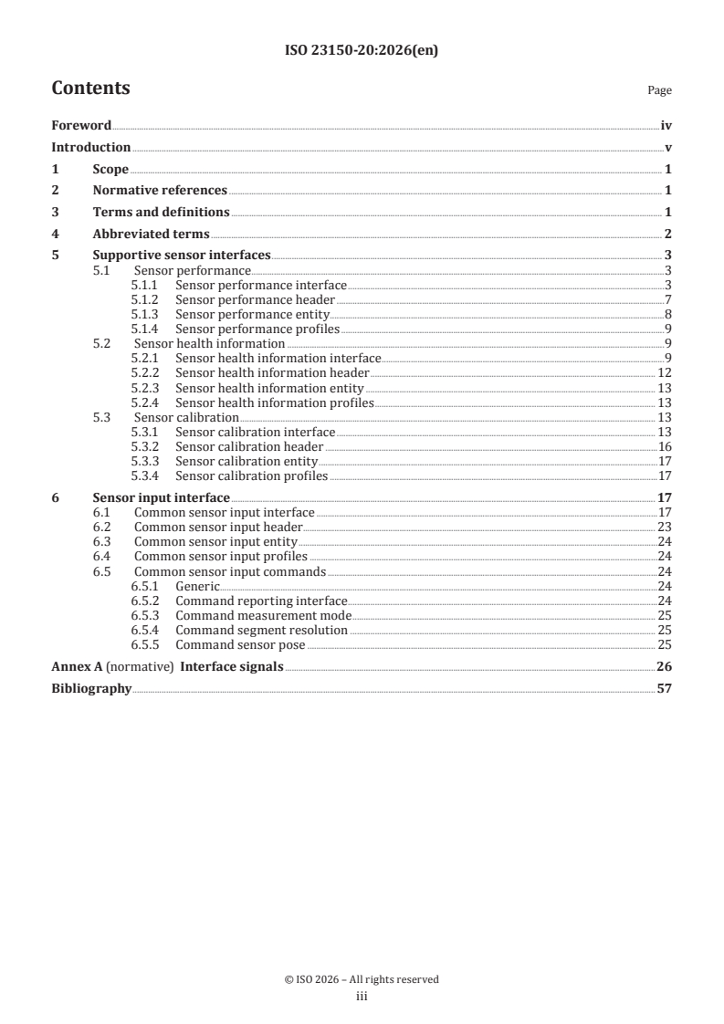
Contents Page
Foreword .iv
Introduction .v
1 Scope . 1
2 Normative references . 1
3 Terms and definitions . 1
4 Abbreviated terms . 2
5 Supportive sensor interfaces . 3
5.1 Sensor performance .3
5.1.1 Sensor performance interface .3
5.1.2 Sensor performance header .7
5.1.3 Sensor performance entity . .8
5.1.4 Sensor performance profiles .9
5.2 Sensor health information .9
5.2.1 Sensor health information interface .9
5.2.2 Sensor health information header . 12
5.2.3 Sensor health information entity . 13
5.2.4 Sensor health information profiles . 13
5.3 Sensor calibration . 13
5.3.1 Sensor calibration interface . 13
5.3.2 Sensor calibration header .16
5.3.3 Sensor calibration entity .17
5.3.4 Sensor calibration profiles .17
6 Sensor input interface . 17
6.1 Common sensor input interface .17
6.2 Common sensor input header . 23
6.3 Common sensor input entity .24
6.4 Common sensor input profiles .24
6.5 Common sensor input commands .24
6.5.1 Generic .24
6.5.2 Command reporting interface .24
6.5.3 Command measurement mode . 25
6.5.4 Command segment resolution . 25
6.5.5 Command sensor pose . 25
Annex A (normative) Interface signals .26
Bibliography .57
iii
Foreword
ISO (the International Organization for Standardization) is a worldwide federation of national standards
bodies (ISO member bodies). The work of preparing International Standards is normally carried out through
ISO technical committees. Each member body interested in a subject for which a technical committee
has been established has the right to be represented on that committee. International organizations,
governmental and non-governmental, in liaison with ISO, also take part in the work. ISO collaborates closely
with the International Electrotechnical Commission (IEC) on all matters of electrotechnical standardization.
The procedures used to develop this document and those intended for its further maintenance are described
in the ISO/IEC Directives, Part 1. In particular, the different approval criteria needed for the different types
of ISO document should be noted. This document was drafted in accordance with the editorial rules of the
ISO/IEC Directives, Part 2 (see www.iso.org/directives).
ISO draws attention to the possibility that the implementation of this document may involve the use of (a)
patent(s). ISO takes no position concerning the evidence, validity or applicability of any claimed patent
rights in respect thereof. As of the date of publication of this document, ISO had not received notice of (a)
patent(s) which may be required to implement this document. However, implementers are cautioned that
this may not represent the latest information, which may be obtained from the patent database available at
www.iso.org/patents. ISO shall not be held responsible for identifying any or all such patent rights.
Any trade name used in this document is information given for the convenience of users and does not
constitute an endorsement.
For an explanation of the voluntary nature of standards, the meaning of ISO specific terms and expressions
related to conformity assessment, as well as information about ISO's adherence to the World Trade
Organization (WTO) principles in the Technical Barriers to Trade (TBT), see www.iso.org/iso/foreword.html.
This document was prepared by Technical Committee ISO/TC 22, Road vehicles, Subcommittee SC 31, Data
communication.
[1] [2] [3]
This first edition of ISO 23150-20, together with ISO 23150-1 , ISO 23150-2 , ISO 23150-11 , ISO 23150-12
[4] [5] [6] [7]
, ISO 23150-13 , ISO 23150-14 and ISO 23150-15 , cancels and replaces ISO 23150:2023, which has
been technically revised.
The main changes are as follows:
— reorganisation of the document structure; use of generic interfaces, generic signals, generic profiles and
[1]
terms and definitions defined in ISO 23150-1 as a basis for this document;
— specific collection of interfaces in separated documents; in this document specific collection of all
supportive and sensor input interfaces;
— revise of the logical interfaces;
— new logical interfaces for sensor calibration.
A list of all parts in the ISO series can be found on the ISO website.
Any feedback or questions on this document should be directed to the user’s national standards body. A
complete listing of these bodies can be found at www.iso.org/members.html.
iv
Introduction
Vehicle environmental perception sensors (single sensor or sensor cluster) provide logical interfaces
according to the ISO 23150 series to the fusion unit or automated driving functions. The fusion unit
generates a surround model and interprets the scene around the vehicle based on the sensor data. Interfaces
are defined on different levels and described in a modular and semantic representation. The interfaces at
the feature level, advanced detection level and detection level are technology specific and differ for each
technology.
Figure 1 shows the schematic and contextual relationships between the documents relating to logical
interfaces of the ISO 23150 series.
Key
scope of the document
Figure 1 — Relationship of the ISO 23150 series
[1]
This document is based on the generic specifications in ISO 23150-1 as shown in Figure 2:
— generic supportive sensor interface;
— generic sensor input interface;
— general level-independent profiles.
v
Key
scope of this document
Figure 2 — Interfaces in the scope of this document and the related interfaces of the ISO 23150
series
This document specifies the additional interfaces for supportive sensor interfaces (SSI) and sensor input
interfaces (SII). These include the supportive sensor interfaces "sensor performance interface" (5.1.1),
"sensor health information interface" (5.2.1) and "sensor calibration interface" (5.3.1) as well as the
sensor input interface "common sensor input interface" (6.1). These interfaces are based on the generic
[1]
specifications of the supportive sensor interface and the sensor input interface in ISO 23150-1 . They can
be supplied by every sensor or sensor cluster. This document references to generic specifications of signals
for the interface header, the generic interface levels and the profiles.
A sensor or sensor cluster may also implement (provide or receive) logical interfaces:
[2]
— on object level (see ISO 23150-2 );
— on feature-, advanced detection- or detection level (see technology specific parts of the ISO 23150 series).
This document is not intended to replace the logical interface specifications of other documents in the
ISO 23150 series.
Table 1 provides an overview over the differences and boundaries between the SSIs.
vi
Table 1 — Brief overview over the differences and boundaries between the SSIs
Sensor performance Sensor health information Sensor calibration
Impairment on observed Impairment in sensor effect Sensor internal Sensor and vehicle
field chain
— rain, fog — dirt, dust — operation — position
— snow — condensation — diagnosis — calibration
— particles (air) — scratch — defects — and so forth
— and so forth — and so forth — cleaning
— and so forth
Classification into several measurement ranges Global information for the Sensor pose in the vehicle
complete sensor
Relevant for safety concept Misalignment: hardware
Relevant E/E information and software calibration
The data of SSI (see 5.1, 5.2, 5.3) can be required to correctly interpret information from object-, feature-,
advanced detection- and detection level interfaces. Data consistency over the sensor’s interfaces needs to be
assured. Supportive sensor interfaces may have LSGs which the sensor provides. If an SSI is not provided,
[8]
the SSI relevant LSGs will be provided by other interfaces as defined (ISO 23150-1:2026 , B.3.4).
The SII (see Clause 6) provides information and parametrisation for a sensor or a sensor cluster. The sensor
receives the SIIs via the in-vehicle communication. Each SII can be sent to the sensor or sensor cluster by
different ECUs. Also, several ECUs can provide complementary parts of the interface (for example, one ECU
provides weather information, and a second ECU provides road information of the common sensor input
interface). During the system design phase, each received SIIs of a sensor or a sensor cluster and the ECUs
that originate these interfaces are defined. The information source and how the signals are provided are
defined during the system design phase to meet the safety and system design requirements (for example,
that the fusion unit may provide certain SIIs).
vii
International Standard ISO 23150-20:2026(en)
Road vehicles — Logical interface between sensors and data
fusion unit for automated driving functions —
Part 20:
Supportive and sensor input interfaces
1 Scope
This document is applicable to road vehicles with automated driving functions and specifies the supportive
sensor interfaces for sensors or sensor clusters:
— sensor performance interface;
— sensor health information interface;
— sensor calibration interface;
and specifies the sensor input interface:
— common sensor input interface.
This document does not provide electrical and mechanical interface specifications. Raw data interfaces are
also excluded.
2 Normative references
The following documents are referred to in the text in such a way that some or all of their content constitutes
requirements of this document. For dated references, only the edition cited applies. For undated references,
the latest edition of the referenced document (including any amendments) applies.
ISO 23150-1:2026, Road vehicles — Logical interface between sensors and data fusion unit for automated
driving functions — Part 1: General information and principles
ISO 23150-1, Road vehicles — Logical interface between sensors and data fusion unit for automated driving
functions — Part 1: General information and principles
3 Terms and definitions
For the purposes of this document, the terms and definitions given in ISO 23150-1 apply.
ISO and IEC maintain terminology databases for use in standardization at the following addresses:
— ISO Online browsing platform: available at https:// www .iso .org/ obp
— IEC Electropedia: available at https:// www .electropedia .org/
4 Abbreviated terms
A2I assign to interface
AD automated driving
ADLI advanced detection level interface
AER alternative entity representation
C conditional
CSII common sensor input interface
D dimensional
DE default enumerators
DLI detection level interface
ECU electronic control unit
EES extended enumeration signal
EM error model
FFT fast Fourier transform
FLI feature level interface
FLP front-left position of the ego-vehicle
FOV field-of-view
FRP front-right position of the ego-vehicle
FWHM full width at half maximum
GPS global positioning system
ID identifier
IQR interquartile range
IR infrared
IRI international roughness index
IV implicit value
LL list length
LSG logical signal group
M mandatory
NIR near infrared
O optional
OLI object level interface
RL requirement level
RLP rear-left position of the ego-vehicle
RRP rear-right position of the ego-vehicle
SCI sensor calibration interface
SHII sensor health information interface
SII sensor input interface
SPI sensor performance interface
SSI supportive sensor interface
UTL unrolling tuple list
VRO value representation optimisation
5 Supportive sensor interfaces
5.1 Sensor performance
5.1.1 Sensor performance interface
The generic specification of the supportive sensor interfaces is defined in ISO 23150-1:2026, Clause 11.
The supportive sensor interfaces shall base on the generic supportive sensor interface as specified in
ISO 23150-1:2026, 11.2. Table 2 provides the logical structure of the SPI.
Table 2 — Sensor performance interface structure
Structure Multiplicity Option
Sensor performance header (5.1.2) 1
a
Segments Multiple Size type:
dynamic/fixed
a
The number of segments are sensor or sensor cluster specific. The contribution is not dependent on the surrounding. The
sensor performance entities are valid for the referenced interfaces in the header.
The logical structure of the SPI shall be implemented in accordance with the interface definition specified
[8]
in Table 3, the signals as defined in Annex A and ISO 23150-1:2026 , Annex A. Furthermore, the generic
[1]
profiles as defined in 5.1.4 and in ISO 23150-1 as well as the signal options defined in ISO 23150-1:2026,
Annex B shall also be considered.
Table 3 — Sensor performance interface
RL LSG RL signal
LSG Signal Option
M/C/O M/C/O
Information: M Interface version ID {major, M Profile: Uniqueness of
interface minor, patch} (ISO 23150-1:2026 interface versioning (ISO
[8] [8]
, A.1.2) 23150-1:2026 , 6.5.1)
Interface ID (ISO 23150-1:2026 O Profile: Uniqueness of
[8]
, A.1.3) interface versioning (ISO
[8]
23150-1:2026 , 6.5.1)
TTabablele 3 3 ((ccoonnttiinnueuedd))
RL LSG RL signal
LSG Signal Option
M/C/O M/C/O
Number of valid serving sensors M Profile: Uniqueness of
[8]
(ISO 23150-1:2026 , A.1.4) interface versioning (ISO
[8]
23150-1:2026 , 6.5.1)
Optimise LL (ISO 23150-
[8]
1:2026 , B.1.2)
Alternative UTL (ISO
[8]
23150-1:2026 , B.1.7)
Key: Sensor ID (ISO 23150-
[8]
1:2026 , A.1.5)
Size type: dynamic/fixed
[8]
Size #: Number of valid serving sensors (ISO 23150-1:2026 , A.1.4)
Sensor ID (ISO 23150-1:2026 M Profile: Uniqueness of
[8]
, A.1.5) interface versioning (ISO
[8]
23150-1:2026 , 6.5.1)
Alternative VRO (ISO
[8]
23150-1:2026 , B.1.4)
Number of valid applicable O Profile: Reference interface
[8] [8]
interfaces (ISO 23150-1:2026 , list (ISO 23150-1:2026 ,
A.2.59) 6.5.14)
Optimise LL (ISO 23150-
[8]
1:2026 , B.1.2)
Alternative UTL (ISO
[8]
23150-1:2026 , B.1.7)
Key: Interface ID reference
[8]
(ISO 23150-1:2026 ,
A.2.60)
Size type: dynamic/fixed
[8]
Size #: Number of valid applicable interfaces (ISO 23150-1:2026 , A.2.59)
Interface ID reference (ISO M Profile: Reference interface
[8] [8]
23150-1:2026 , A.2.60) list (ISO 23150-1:2026 ,
6.5.14)
Alternative VRO (ISO
[8]
23150-1:2026 , B.1.4)
Time stamp – <…> (ISO 23150- M
[8]
1:2026 , A.1.6)
Message counter (ISO 23150- O
[8]
1:2026 , A.1.7.2)
Interface cycle time (ISO 23150- O
[8]
1:2026 , A.1.8)
Interface cycle time – variation O
[8]
(ISO 23150-1:2026 , A.1.9)
Data qualifier (ISO 23150-1:2026 M Optimise DE (ISO 23150-
[8] [8]
, A.1.10) 1:2026 , B.1.8)
Optimise EES (ISO 23150-
[8]
1:2026 , B.1.9)
Information: O Vanishing point {azimuth, eleva- M
sensor tion} (A.1.2)
surrounding
Vanishing point {azimuth, eleva- O Implementation EM (ISO
[8]
tion} – error (A.1.3) 23150-1:2026 , B.4.2)
Field of view segments
TTabablele 3 3 ((ccoonnttiinnueuedd))
RL LSG RL signal
LSG Signal Option
M/C/O M/C/O
Field of view M Number of valid field-of-view M Optimise LL (ISO 23150-
[8]
segments segments (A.1.4.1) 1:2026 , B.1.2)
information
Alternative UTL (ISO
[8]
23150-1:2026 , B.1.7)
Key: Segment azimuth
{begin, end} (ISO 23150-
[8]
1:2026 , A.2.64) and
Segment elevation {begin,
[8]
end} (ISO 23150-1:2026 ,
A.2.65)
Size type: Dynamic/fixed
Size #: Number of valid field-of-view segments (A.1.4.1)
↪ Status M Segment azimuth {begin, end} M Profile: Segment (ISO
[8] [8]
(ISO 23150-1:2026 , A.2.64) 23150-1:2026 , 6.5.16)
Alternative VRO (ISO
[8]
23150-1:2026 , B.1.4)
Segment elevation {begin, O Profile: Segment (ISO
[8] [8]
end} (ISO 23150-1:2026 , 23150-1:2026 , 6.5.16)
A.2.65)
Alternative VRO ISO 23150-
[8]
1:2026 , B.1.4)
Measurement grid resolution O
{radial distance, azimuth,
elevation} (A.2.2)
Beam divergence {azimuth, O
elevation} (A.2.3)
Range gain (A.2.4) O
Blockage status (A.2.5) M Optimise DE (ISO 23150-
[8]
1:2026 , B.1.8)
Optimise EES (ISO 23150-
[8]
1:2026 , B.1.9)
↪ Field-of-view O Number of valid field-of-view M Optimise LL (ISO 23150-
[8]
reduction reduction reasons (A.2.6) 1:2026 , B.1.2)
Alternative UTL (ISO
[8]
23150-1:2026 , B.1.7)
Key: Field-of-view reduction
reason type (A.2.7)
Size type: Dynamic/fixed
Size #: Number of valid field-of-view reduction reasons (A.2.6)
Field-of-view reduction M Alternative VRO (ISO
[8]
reason type (A.2.7) 23150-1:2026 , B.1.4)
Optimise DE (ISO 23150-
[8]
1:2026 , B.1.8)
Optimise EES (ISO 23150-
[8]
1:2026 , B.1.9)
Field-of-view reduction M
reason type – confidence
(A.2.8)
TTabablele 3 3 ((ccoonnttiinnueuedd))
RL LSG RL signal
LSG Signal Option
M/C/O M/C/O
↪ Real-world C (ISO 23150- Number of valid recognisable M Optimise LL (ISO 23150-
[8] [8]
object 1:2026 , B.3.2) object types (A.2.9) 1:2026 , B.1.2)
recognition Exist: OLI
Alternative UTL (ISO
[8]
capabilities and in scope
23150-1:2026 , B.1.7)
of signals
Key: Recognised object type
"Interface ID
(A.2.10)
reference" (ISO
Size type: Dynamic/fixed
23150-1:2026
Size #: Number of valid recognisable object types (A.2.9)
[8]
, A.2.60)
Recognised object type M Alternative VRO (ISO
[8]
(A.2.10) 23150-1:2026 , B.1.4)
Optimise DE (ISO 23150-
[8]
1:2026 , B.1.8)
Optimise EES (ISO 23150-
[8]
1:2026 , B.1.9)
Detection range radial dis- M
tance {begin, end} (A.2.11)
True positive rate (A.2.12) O
False positive rate (A.2.13) O
Positive predictive value O
(A.2.14)
↪ Reference C (ISO 23150- Number of valid reference M Optimise LL (ISO 23150-
[8] [8]
target 1:2026 , B.3.2) target types (A.2.15) 1:2026 , B.1.2)
recognition Exist: FLI, DLI
Size type: Dynamic/fixed
capabilities and in scope
Size #: Number of valid reference target types (A.2.15)
of signals
Reference target type C (ISO 23150- Optimise DE (ISO 23150-
"Interface ID
[8] [8]
(A.2.16) 1:2026 , B.2.2) 1:2026 , B.1.8)
reference" (ISO
Relevant: cam-
Optimise EES (ISO 23150-
23150-1:2026
[8]
[8] era
1:2026 , B.1.9)
, A.2.60)
Radar cross section refer- C (ISO 23150-
[8]
ence target (A.2.17) 1:2026 , B.2.2)
Relevant: radar
Reflectivity reference C (ISO 23150-
[8]
target (A.2.18) 1:2026 , B.2.2)
Relevant: lidar,
ultrasonic
Detection range radial dis- M
tance {begin, end} (A.2.11)
True positive rate (A.2.12) O
Relative radial velocity O
range {begin, end} (A.2.19)
Signal to noise ratio (ISO M Optimise IV (ISO 23150-
[8] [8]
23150-1:2026 , A.2.66) 1:2026 , B.1.6)
Spatial separability {radial O
distance, azimuth, eleva-
tion} (A.2.20)
Velocity separability O
{radial distance, azimuth,
elevation} (A.2.21)
The signals referring to angles as well as distances in the segments always refer to the sensor coordinate
system and its origin. This affects the signals:
[8]
— Segment azimuth {begin, end} (ISO 23150-1:2026 , A.2.64);
[8]
— Segment elevation {begin, end} (ISO 23150-1:2026 , A.2.65);
— Measurement grid resolution {radial distance, azimuth, elevation} (A.2.2);
— Detection range radial distance {begin, end} (A.2.11);
— Relative radial velocity range {begin, end} (A.2.19);
— Spatial separability {radial distance, azimuth, elevation} (A.2.20);
— Velocity separability {radial distance, azimuth, elevation} (A.2.21).
The correlation between vehicle- and sensor coordinate system is determined by the sensor origin point and
[8]
the sensor orientation of the sensor [see "Profile: Sensor pose" (ISO 23150-1:2026 , 6.5.5)].
The geometric information of the SSIs references the vehicle coordinate system [see "Profile: Vehicle
[8]
coordinate system" (ISO 23150-1:2026 , 6.5.4)] as well as the sensor coordinate system [see "Profile:
[8]
Sensor pose" (ISO 23150-1:2026 , 6.5.5)].
5.1.2 Sensor performance header
Table 4 defines the interface header for sensor performance information and the changes due to the
adaptation in comparison to the "generic supportive sensor header" as specified in ISO 23150-1:2026, 11.3,
which shall be used as the interface header. The header of the SPI specifies the list of valid FOV segment
entities (see 5.1.3).
Table 4 — Specific signal grouping: Sensor performance header
Signal RL signal Option
Interface version ID {major, minor, patch} Mandatory Profile: Uniqueness of interface versioning
[8] [8]
(ISO 23150-1:2026 , A.1.2) (ISO 23150-1:2026 , 6.5.1)
[8]
Interface ID (ISO 23150-1:2026 , A.1.3) Optional Profile: Uniqueness of interface versioning
[8]
(ISO 23150-1:2026 , 6.5.1)
Number of valid serving sensors (ISO 23150- Mandatory Profile: Uniqueness of interface versioning
[8] [8]
1:2026 , A.1.4) (ISO 23150-1:2026 , 6.5.1)
[8]
Optimise LL (ISO 23150-1:2026 , B.1.2)
[8]
Alternative UTL (ISO 23150-1:2026 , B.1.7)
[8]
Key: Sensor ID (ISO 23150-1:2026 , A.1.5)
[8]
↪ Sensor ID (ISO 23150-1:2026 , A.1.5) Mandatory Profile: Uniqueness of interface versioning
[8]
(ISO 23150-1:2026 , 6.5.1)
[8]
Alternative VRO (ISO 23150-1:2026 , B.1.4)
Number of valid applicable interfaces (ISO Optional Profile: Reference interface list (ISO 23150-
[8] [8]
23150-1:2026 , A.2.59) 1:2026 , 6.5.14)
[8]
Optimise LL (ISO 23150-1:2026 , B.1.2)
[8]
Alternative UTL (ISO 23150-1:2026 , B.1.7)
Key: Interface ID reference (ISO 23150-
[8]
1:2026 , A.2.60)
↪ Interface ID reference (ISO 23150-1:2026 Mandatory Profile: Reference interface list (ISO 23150-
[8] [8]
, A.2.60) 1:2026 , 6.5.14)
[8]
Alternative VRO (ISO 23150-1:2026 , B.1.4)
[8]
Mandatory
Time stamp – <…> (ISO 23150-1:2026 ,
A.1.6)
[8]
Message counter (ISO 23150-1:2026 , Optional
A.1.7.2)
a
The RL of the additional LSG is optional.
b [8]
Further signals may be added to this header as defined in "Need of logical signal group" (ISO 23150-1:2026 , B.3.4) (see
cell options).
c
The number of field of view segments is deterministic. No performance information is required.
TTabablele 4 4 ((ccoonnttiinnueuedd))
Signal RL signal Option
[8]
Interface cycle time (ISO 23150-1:2026 , Optional
A.1.8)
Interface cycle time – variation (ISO 23150- Optional
[8]
1:2026 , A.1.9)
[8] [8]
Data qualifier (ISO 23150-1:2026 , A.1.10) Mandatory Optimise DE (ISO 23150-1:2026 , B.1.8)
[8]
Optimise EES (ISO 23150-1:2026 , B.1.9)
a
Vanishing point {azimuth, elevation} (A.1.2) Mandatory
a [8]
Vanishing point {azimuth, elevation} – error Optional Implementation EM (ISO 23150-1:2026 ,
(A.1.3) B.4.2)
b
... Need of logical signal group (ISO 23150-
[8]
1:2026 , B.3.4)
Profile: Vehicle coordinate system (ISO
[8]
23150-1:2026 , 6.5.4)
[8]
Profile: Sensor pose (ISO 23150-1:2026 ,
6.5.5)
[8]
Profile: Calibration (ISO 23150-1:2026 ,
6.5.6)
[8]
Profile: Sensor cluster (ISO 23150-1:2026 ,
6.5.7)
Field of view segments
[8]
Number of valid field-of-view segments Mandatory Optimise LL (ISO 23150-1:2026 , B.1.2)
[8]
(A.1.4.1)
Alternative UTL (ISO 23150-1:2026 , B.1.7)
Key: Segment azimuth {begin, end} (ISO
[8]
23150-1:2026 , A.2.64) and Segment ele-
[8]
vation {begin, end} (ISO 23150-1:2026 ,
A.2.65)
c
↪ Field of view segment entities
a
The RL of the additional LSG is optional.
b [8]
Further signals may be added to this header as defined in "Need of logical signal group" (ISO 23150-1:2026 , B.3.4) (see
cell options).
c
The number of field of view segments is deterministic. No performance information is required.
5.1.3 Sensor performance entity
Each sensor performance segment for FOV of a sensor shall describe the performance in this segment and
consists of several LSGs.
— Status: the status describes the geometry of the FOV segment.
— Field-of-view reduction causes: the FOV reduction causes describe the causes (for example, extrinsic
or intrinsic) for an FOV reduction.
— Real-world object recognition rates: the real-world object recognition rates describe the estimated
recognition rates for real-world recognition of different real-world objects.
— Reference target recognition rates: the reference target recognition rates describe the estimated
recognition rates for synthetic, well-defined recognition of different synthetic, well-defined objects.
For two valid but geometric overlapping FOV segments (azimuth-, elevation range), the values for the earlier
defined segment in the list will always stay valid. So typically, the segments will be defined from the inside
to the outside (due to timing reasons, special regions of interest are more important than the general FOV
segments and the special regions of interest shall be known to be subtracted from the general FOV segment).
5.1.4 Sensor performance profiles
For SPI, no specific profiles are defined.
5.2 Sensor health information
5.2.1 Sensor health information interface
[8]
The generic specification of the supportive sensor interfaces is defined in ISO 23150-1:2026 , Clause
11. The supportive sensor interfaces shall base on the generic supportive sensor interface as specified in
[8]
ISO 23150-1:2026 , 11.2. Table 5 provides the logical structure of the SHII.
Table 5 — Sensor health information interface structure
Structure Multiplicity Option
Sensor health information header (5.2.2) 1
a
Sensor health information 1 Size type:
fixed
a
Sensor cluster definition 1 Size type:
fixed
a
The sensor health entity is valid for the entire sensor or sensor cluster.
The logical structure of the SHII shall be implemented in accordance with the interface definition
[8]
specified in Table 6, the signals as defined in Annex A and ISO 23150-1:2026 , Annex A. Furthermore,
[8]
the generic profiles as defined in 5.2.4 and in ISO 23150-1:2026 as well as the signal options defined in
[8]
ISO 23150-1:2026 , Annex B shall also be considered.
Table 6 — Sensor health information interface
RL LSG RL signal
LSG Signal Option
M/C/O M/C/O
Information: M Interface version ID {major, M Profile: Uniqueness of
interface minor, patch} (ISO 23150- interface versioning (ISO
[8] [8]
1:2026 , A.1.2) 23150-1:2026 , 6.5.1)
Interface ID (ISO 23150- O Profile: Uniqueness of
[8]
1:2026 , A.1.3) interface versioning (ISO
[8]
23150-1:2026 , 6.5.1)
Number of valid serving M Profile: Uniqueness of
sensors (ISO 23150-1:2026 interface versioning (ISO
[8] [8]
, A.1.4) 23150-1:2026 , 6.5.1)
Optimise LL (ISO 23150-
[8]
1:2026 , B.1.2)
Alternative UTL (ISO
[8]
23150-1:2026 , B.1.7)
Key: Sensor ID (ISO 23150-
[8]
1:2026 , A.1.5)
Size type: dynamic/fixed
[8]
Size #: Number of valid serving sensors (ISO 23150-1:2026 , A.1.4)
Sensor ID (ISO 23150- M Profile: Uniqueness of
[8]
1:2026 , A.1.5) interface versioning (ISO
[8]
23150-1:2026 , 6.5.1)
Alternative VRO (ISO
[8]
23150-1:2026 , B.1.4)
Time stamp – <…> (ISO M
[8]
23150-1:2026 , A.1.6)
Message counter (ISO 23150- O
[8]
1:2026 , A.1.7.2)
TTabablele 6 6 ((ccoonnttiinnueuedd))
RL LSG RL signal
LSG Signal Option
M/C/O M/C/O
Interface cycle time (ISO O
[8]
23150-1:2026 , A.1.8)
Interface cycle time – vari- O
[8]
ation (ISO 23150-1:2026 ,
A.1.9)
Data qualifier (ISO 23150- M Optimise DE (ISO 23150-
[8] [8]
1:2026 , A.1.10) 1:2026 , B.1.8)
Optimise EES (ISO 23150-
[8]
1:2026 , B.1.9)
Sensor health information
Status M Number of valid sensor clus- M Optimise LL (ISO 23150-
[8]
ter operation modes (A.2.22) 1:2026 , B.1.2)
Alternative UTL (ISO
[8]
23150-1:2026 , B.1.7)
Key: Sensor cluster opera-
tion mode (A.2.23)
Size type: Dynamic/fixed
Size #: Number of valid sensor cluster operation modes (A.2.22)
Sensor cluster operation M Alternative VRO (ISO
[8]
mode (A.2.23) 23150-1:2026 , B.1.4)
Optimise DE (ISO 23150-
[8]
1:2026 , B.1.8)
Optimise EES (ISO 23150-
[8]
1:2026 , B.1.9)
Sensor defect recognised M Optimise DE (ISO 23150-
[8]
(A.2.24) 1:2026 , B.1.8)
Optimise EES (ISO 23150-
[8]
1:2026 , B.1.9)
Sensor defect reason (A.2.25) M Optimise DE (ISO 23150-
[8]
1:2026 , B.1.8)
Optimise EES (ISO 23150-
[8]
1:2026 , B.1.9)
Supply voltage status M Optimise DE (ISO 23150-
[8]
(A.2.26) 1:2026 , B.1.8)
Optimise EES (ISO 23150-
[8]
1:2026 , B.1.9)
Sensor temperature status M Optimise DE (ISO 23150-
[8]
(A.2.27) 1:2026 , B.1.8)
Optimise EES (ISO 23150-
[8]
1:2026 , B.1.9)
Number of valid sensor input M Optimise LL (ISO 23150-
[8]
signal statuses (A.2.28) 1:2026 , B.1.2)
Alternative UTL (ISO
[8]
23150-1:2026 , B.1.7)
Key: Sensor input signal
type (A.2.29)
TTabablele 6 6 ((ccoonnttiinnueuedd))
RL LSG RL signal
LSG Signal Option
M/C/O M/C/O
Size type: Dynamic/fixed
Size #: Number of valid sensor input signal statuses (A.2.28)
Sensor input signal type M Alternative VRO (ISO
[8]
(A.2.29) 23150-1:2026 , B.1.4)
Optimise DE (ISO 23150-
[8]
1:2026 , B.1.8)
Optimise EES (ISO 23150-
[8]
1:2026 , B.1.9)
Sensor input signal status M Optimise DE (ISO 23150-
[8]
(A.2.30) 1:2026 , B.1.8)
Optimise EES (ISO 23150-
[8]
1:2026 , B.1.9)
Sensor externally disturbed O Optimise DE (ISO 23150-
[8]
(A.2.31) 1:2026 , B.1.8)
Optimise EES (ISO 23150-
[8]
1:2026 , B.1.9)
Sensor transmit power re- O Optimise DE (ISO 23150-
[8]
duced (A.2.32) 1:2026 , B.1.8)
Optimise EES (ISO 23150-
[8]
1:2026 , B.1.9)
Sensor heating status O Optimise DE (ISO 23150-
[8]
(A.2.33) 1:2026 , B.1.8)
Optimise EES (ISO 23150-
[8]
1:2026 , B.1.9)
Sensor cleaning status O Optimise DE (ISO 23150-
[8]
(A.2.34) 1:2026 , B.1.8)
Optimise EES (ISO 23150-
[8]
1:2026 , B.1.9)
Sensor time sync (A.2.35) O Optimise DE (ISO 23150-
[8]
1:2026 , B.1.8)
Optimise EES (ISO 23150-
[8]
1:2026 , B.1.9)
Sensor time sync offset value C (ISO 23150-
[8]
(A.2.36) 1:2026 , B.2.3)
* The signal
"Sensor time
sync" (A.2.35)
has
"STS_Offset"
or a similar
enumerator de-
fined during the
system design
phase.
Sensor cluster definition
Sensor cluster O Number of valid sensors (ISO M Profile: Sensor cluster (ISO
[8] [8]
Need of logical 23150-1:2026 , A.2.16) 23150-1:2026 , 6.5.7)
signal group (ISO
Optimise LL (ISO 23150-
[8]
23150-1:2026 [8]
1:2026 , B.1.2)
B.3.4)
Alternative UTL (ISO
[8]
23150-1:2026 , B.1.7)
Key: Sensor ID reference
[8]
(ISO 23150-1:2026 ,
A.2.17)
TTabablele 6 6 ((ccoonnttiinnueuedd))
RL LSG RL signal
LSG Signal Option
M/C/O M/C/O
Size type: Dynamic/fixed
[8]
Size #: Number of valid sensors (ISO 23150-1:2026 , A.2.16)
Sensor ID reference (ISO M Profile: Sensor cluster (ISO
[8] [8]
23150-1:2026 , A.2.17) 23150-1:2026 , 6.5.7)
Alternative VRO (ISO
[8]
23150-1:2026 , B.1.4)
5.2.2 Sensor health information header
Table 7 defines the interface header for sensor health information and the changes due to the adaptation in
[8]
comparison to the "generic supportive sensor header" as specified in ISO 23150-1:2026 , 11.3, which shall
be used as the interface header.
Table 7 — Specific signal grouping: Sensor health information header
Signal RL signal Option
Interface version ID {major, minor, patch} Mandatory Profile: Uniqueness of interface versioning
[8] [8]
(ISO 23150-1:2026 , A.1.2) (ISO 23150-1:2026 , 6.5.1)
[8]
Interface ID (ISO 23150-1:2026 , A.1.3) Optional Profile: Uniqueness of interface versioning
[8]
(ISO 23150-1:2026 , 6.5.1)
Number of valid serving sensors Mandatory Profile: Uniqueness of interface versioning
[8] [8]
(ISO 23150-1:2026 , A.1.4) (ISO 23150-1:2026 , 6.5.1)
[8]
Optimise LL (ISO 23150-1:2026 , B.1.2)
[8]
Alternative UTL (ISO 23150-1:2026 , B.1.7)
[8]
Key: Sensor ID (ISO 23150-1:2026 , A.1.5)
[8]
↪ Sensor ID (ISO 23150-1:2026 , A.1.5) Mandatory Profile: Uniqueness of interface versioning
[8]
(ISO 23150-1:2026 , 6.5.1)
[8]
Alternative VRO (ISO 23150-1:2026 , B.1.4)
[8]
Time stamp – <…> (ISO 23150-1:2026 , Mandatory
A.1.6)
[8]
Message counter (ISO 23150-1:2026 , Optional
A.1.7.2)
[8]
Interface cycle time (ISO 23150-1:2026 , Optional
A.1.8)
Interface cycle time – variation Optional
[8]
(ISO 23150-1:2026 , A.1.9)
[8] [8]
Data qualifier (ISO 23150-1:2026 , A.1.10) Mandatory Optimise DE (ISO 23150-1:2026 , B.1.8)
[8]
Optimise EES (ISO 23150-1:2026 , B.1.9)
a
... Need of logical signal group (ISO 23150-
[8]
1:2026 , B.3.4)
Profile: Vehicle coordinate system (ISO
[8]
23150-1:2026 , 6.5.4)
[8]
Profile: Sensor pose (ISO 23150-1:2026 ,
6.5.5)
[8]
Profile: Calibration (ISO 23150-1:2026 ,
6.5.6)
Sensor health information
Sensor cluster definition
a [8]
Further signals may be added to this header as defined in "Need of logical signal group" (ISO 23150-1:2026 , B.3.4) (see
cell options).
5.2.3 Sensor health information entity
Sensor health information of a sensor shall describe global sensor statuses and consists of several LSGs.
This interface provides a single sensor health information entity and the sensor cluster definition entity
for the entire sensor and not a list of entities. The sensor cluster definition entity types is an LSG with the
[8]
requirement "Need of logical signal group" as specified in ISO 23150-1:2026 , B.3.4, which shall be used.
— Status: the status describes the global statuses of the sensor.
— Sensor cluster: the sensor cluster defines the set of sensors which defines the entire sensor cluster.
5.2.4 Sensor health information profiles
For SHI, no specific profiles are defined.
5.3 Sensor calibration
5.3.1 Sensor calibration interface
[8]
The generic specification of the supportive sensor interfaces is defined in ISO 23150-1:2026 , Clause 11.
[8]
The supportive sensor interfaces shall base on the generic supportive sensor interface ISO 23150-1:2026 ,
11.2. Table 8 provides the logical structure of the SCI.
Table 8 — Sensor calibration interface structure
Structure Multiplicity Option
Sensor calibration header (5.2.2) 1
a
Vehicle coordinate system 1 Size type:
fixed
a
Sensor pose 1 Size type:
fixed
a
Calibration 1 Size type:
fixed
a
The entity is valid for the entire sensor or sensor cluster.
The logical structure of the SCI shall be implemented in accordance with the interface definition specified in
[8]
Table 9, the signals as defined in Annex A and ISO 23150-1:2026 , Annex A. Furthermore, the generic profiles
[8] [8]
as defined in 5.3.4 and inISO 23150-1:2026 as well as the signal options defined in ISO 23150-1:2026 ,
Annex B shall also be considered.
Table 9 — Sensor calibration interface
RL LSG RL signal
LSG Signal Option
M/C/O M/C/O
Information: M Interface version ID M Profile: Uniqueness of interface
[8]
interface {major, minor, patch} versioning (ISO 23150-1:2026 ,
[8]
(ISO 23150-1:2026 , 6.5.1)
A.1.2)
Interface ID (ISO O Profile: Uniqueness of interface
[8] [8]
23150-1:2026 , versioning (ISO 23150-1:2026 ,
A.1.3) 6.5.1)
TTabablele 9 9 ((ccoonnttiinnueuedd))
RL LSG RL signal
LSG Signal Option
M/C/O M/C/O
Number of valid M Profile: Uniqueness of interface
[8]
serving sensors (ISO versioning (ISO 23150-1:2026 ,
[8]
23150-1:2026 , 6.5.1)
A.1.4)
Optimise LL (ISO 23150-1:2026
[8]
, B.1.2)
Alternative UTL (ISO 23150-
[8]
1:2026 , B.1.7)
Key: Sensor ID (ISO 23150-1:2026
[8]
, A.1.5)
Size type: dynamic/fixed
[8]
Size #: Number of valid serving sensors (ISO 23150-1:2026 ,
A.1.4)
Sensor ID (ISO M Profile: Uniqueness of interface
[8] [8]
23150-1:2026 , versioning (ISO 23150-1:2026 ,
A.1.5) 6.5.1)
Alternative VRO (ISO 23150-
[8]
1:2026 , B.1.4)
Time stamp – <…> M
[8]
(ISO 23150-1:2026 ,
A.1.6)
Message counter (ISO O
[8]
23150-1:2026 ,
A.1.7.2)
Interface cycle time O
[8]
(ISO 23150-1:2026 ,
A.1.8)
Interface cycle time – O
variation (ISO 23150-
[8]
1:2026 , A.1.9)
Data qualifier (ISO M Optimise DE (ISO 23150-1:2026
[8] [8]
23150-1:2026 , , B.1.8)
A.1.10)
Optimise EES (ISO 23150-1:2026
[8]
, B.1.9)
Vehicle coordinate system
Vehicle coordinate M Vehicle coordinate M Profile: Vehicle coordinate system
[8]
system information Need of logical signal system type (ISO (ISO 23150-1:2026 , 6.5.4)
[8]
group (ISO 23150- 23150-1:2026 ,
Optimise IV (ISO 23150-1:2026
[8]
1:2026 , B.3.4) A.2.2) [8]
, B.1.6)
Sensor pose
Sensor pose M Sensor origin point M Profile: Sensor pose (ISO 23150-
[8]
information Need of logical signal {x, y, z} (ISO 23150- 1:2026 , 6.5.5)
[8]
group (ISO 23150- 1:2026 , A.2.3)
[8]
1:2026 , B.3.4)
Sensor origin point O Profile: Sensor pose (ISO 23150-
[8]
{x, y, z} – error (ISO 1:2026 , 6.5.5)
[8]
23150-1:2026 ,
Implementation EM (ISO 23150-
[8]
A.2.4)
1:2026 , B.4.2)
Sensor orientation M Profile: Sensor pose (ISO 23150-
[8]
{yaw, pitch, roll} (ISO 1:2026 , 6.5.5)
[8]
23150-1:2026 ,
A.2.5)
TTabablele 9 9 ((ccoonnttiinnueuedd))
RL LSG RL signal
LSG Sig
...