

ISO 7240-33
(Main)Fire detection and alarm systems — Part 33: Thermal imaging fire detectors
- Abstract
This document specifies requirements, test methods and performance criteria for thermal imaging fire detectors (TIFD), which operate in the infrared spectrum, for use in fire detection and alarm systems installed in and around buildings (see ISO 7240-1)
- Status
- Not Published
- Technical Committee
- ISO/TC 21/SC 3 - Fire detection and alarm systems
- Drafting Committee
- ISO/TC 21/SC 3 - Fire detection and alarm systems
- Current Stage
- 6000 - International Standard under publication
- Start Date
- 10-Sep-2026
- Completion Date
- 10-Oct-2026
Buy Documents

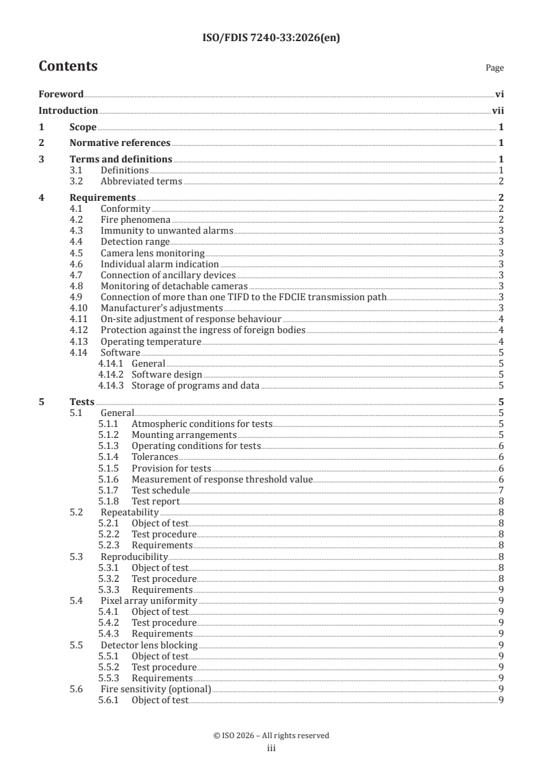
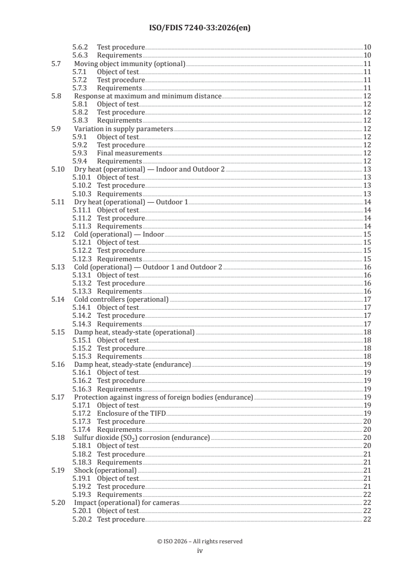
ISO/FDIS 7240-33 - Fire detection and alarm systems — Part 33: Thermal imaging fire detectors
REDLINE ISO/FDIS 7240-33 - Fire detection and alarm systems — Part 33: Thermal imaging fire detectors
ISO 7240-33 is an ISO standard for thermal imaging fire detectors (TIFD) used in fire detection and alarm systems installed in and around buildings. It specifies the requirements, test methods, and performance criteria for detectors that operate in the infrared spectrum, so manufacturers, test laboratories, and system specifiers can judge whether a TIFD is suitable for a given application.
What does ISO 7240-33 specify?
ISO 7240-33 specifies how thermal imaging fire detectors are to be designed, tested, marked, and documented for building fire detection and alarm systems. It focuses on TIFD that detect fire by analysing thermal images, and it sets the scope around normal building applications rather than special-risk products with features outside the document’s test and assessment methods.
The document is organized into clauses for scope, normative references, terms and definitions, requirements, tests, test report, marking, and data. It also includes three normative annexes that define the fire test room, the flaming liquid fire used in sensitivity testing, and the smoke-measuring instruments used in those tests.
| Annex | What it covers |
|---|---|
| Annex A | Fire test room arrangement, size, instruments, and specimen placement |
| Annex B | Flaming liquid (n-heptane) fire TF5, fuel, arrangement, ignition, and validity criteria |
| Annex C | Smoke-measuring instruments, including obscuration meter and measuring ionization chamber |
What are the key requirements of ISO 7240-33?
ISO 7240-33 requires a TIFD to meet general conformity rules, declared performance limits, environmental robustness, and documentation controls. In practice, this means the manufacturer must state what the detector is intended to see, prove that it alarms when it should, and show that faults are raised when important parts are blocked, disconnected, or damaged.
Declared detection behavior and alarm handling
Clause 4.2 requires the manufacturer to declare the fire stimulus the TIFD is designed to respond to. The stimulus is infrared-radiating objects and may optionally include flames. This matters because the installation and test evidence need to match the detector’s intended use.
Clause 4.4 requires the manufacturer to declare the detection ranges and the size of the hot object that can be detected at those distances. Clause 5.8 then checks response at the claimed minimum and maximum distance. For buyers and specifiers, this is the part that links the claimed coverage to the actual installation geometry.
Clause 4.5 requires a fault signal if complete lens obscuration prevents fire detection in the operating FOV. Clause 4.8 requires detached cameras to be monitored so that disconnection produces a fault signal. These requirements are important because a detector that cannot see or loses a camera must not silently continue as if it were healthy.
Immunity, indication, and system connection
Clause 4.3 requires immunity from phenomena that could cause unwanted alarms, and the related tests are only performed where immunity is claimed. Clause 5.7 also allows optional moving object immunity claims, but only when the manufacturer clearly states the claim in a form that can be tested. This helps match the detector’s behavior to real sites where heat sources may move through the scene.
Clause 4.6 requires an individual red alarm indicator where the detector does not display the image of the FOV to the user. The indicator has to identify the unit in alarm until reset, and the document gives visibility conditions when the indicator is mounted on the camera. This matters for maintenance and incident response because staff need to know which detector has triggered.
Clause 4.7 allows ancillary device connections, but open- or short-circuit failures on those connections must not stop the detector operating correctly. Clause 4.9 protects shared FDCIE transmission paths so that a single transmission fault or one detector’s fault signal does not block alarm signaling from other TIFD. In practice, the system should remain usable even if one branch or device fails.
Settings, software, enclosure, and temperature
Clause 4.10 requires manufacturer settings, including response behavior, to be changeable only by special means or by seal removal. Clause 4.11 allows on-site adjustment only under controlled access, and any setting that does not conform must be clearly identified as nonconforming. This helps prevent accidental commissioning in a mode that does not meet the standard.
Clause 4.12 requires the manufacturer to declare an enclosure protection rating from IEC 60529, with indoor use at IP30 or higher and outdoor use at IP54 or higher. Clause 4.13 requires a declared operating temperature class, including indoor controlled, indoor, Outdoor 1, and Outdoor 2 ranges. These declarations tell the installer whether the detector can survive the planned location.
Clause 4.14 applies to detectors that rely on software control. It requires a modular software structure, protection against invalid data and deadlock, non-volatile storage of the compliant program and preset data, and retention or recovery of site-specific data after power loss. That means the software must be controlled enough to remain stable and recoverable in the field.
Testing and endurance
Clause 5 covers repeatability, reproducibility, pixel array uniformity, lens blocking, optional fire sensitivity, distance response, supply variation, thermal and humidity exposure, ingress, sulfur dioxide corrosion, shock, impact, vibration, and EMC immunity. These tests check not only alarm response but also whether the detector keeps working after realistic environmental and mechanical stress.
What terms does ISO 7240-33 define?
- controller - Information technology equipment that connects to thermal image fire detectors and records and/or performs analytics on images.
- response threshold value (RTV) - The temperature at which a detector signals an alarm in the specified test method.
- field of view (FOV) - The image captured by the TIFD; it may be described by angle or by width and height at a specified distance.
- thermal image fire detector (TIFD) - A self-contained device or distributed system that analyses thermal images to measure temperature and detect likely fire presence.
- FDCIE - Fire detection control and indicating equipment, the system transmission path the detector may connect to.
- IP - Ingress protection, the enclosure rating used for dust and water protection.
- EM - Electromagnetic compatibility, used in the EMC immunity tests and related abbreviated terms.
Who uses ISO 7240-33?
ISO 7240-33 is used by TIFD manufacturers, fire alarm system designers, test laboratories, certification bodies, installers, and quality managers. Manufacturers use it to design the detector, prepare software and hardware documentation, and mark the product correctly.
Test laboratories use it to set up the fire test room, run the fire and environmental tests, and record the response threshold values and fault behavior. Installers and system integrators use it to match camera, controller, FOV, enclosure rating, operating temperature, and transmission-path compatibility to the site.
Buyers and specifiers use it to compare TIFD products on a common basis. Quality and compliance teams use it to check whether the detector’s declared performance, marking, and documentation match the tested configuration.
Which standards are used with ISO 7240-33?
ISO 7240-33 cites several external standards that supply the test methods and protection codes used in its own procedures.
- ISO 7240-1 - Provides the general and definitions framework for fire detection and alarm systems.
- IEC 60068-2-1 - Supplies cold test methods used in the low-temperature conditioning tests.
- IEC 60068-2-2 - Supplies dry heat test methods used in the high-temperature conditioning tests.
- IEC 60068-2-6 - Supplies sinusoidal vibration test methods.
- IEC 60068-2-27 - Supplies shock test methods.
- IEC 60068-2-42 - Supplies the sulfur dioxide corrosion test method.
- IEC 60068-2-75 - Supplies hammer test methods used for impact testing of controllers.
- IEC 60068-2-78 - Supplies damp heat, steady-state test methods.
- IEC 60529 - Defines IP enclosure ratings.
- IEC 62262 - Defines IK impact protection codes and the spring-hammer apparatus used for camera impact testing.
- IEC 62599-2 - Supplies EMC immunity test requirements for fire and security alarm system components.
What does the ISO 7240-33 document contain?
ISO 7240-33 contains detailed test methods for response threshold value, repeatability, reproducibility, pixel array uniformity, lens blocking, distance response, and optional sensitivity or moving-object claims. It also contains conditioning tests for dry heat, cold, damp heat, sulfur dioxide, shock, impact, vibration, and EMC immunity, so the detector can be assessed both for fire response and for survival in service conditions.
The annexes provide the fire test room layout, the TF5 flaming liquid fire, and the smoke-measuring instruments used to quantify test conditions and response. Annex C is especially technical because it defines how obscuration and ionization-based smoke measurements are made, including the meter characteristics and the measuring ionization chamber arrangement.
The document also contains rules for test reporting, marking, and manufacturer data. In practice, these parts tell labs what to record, and they tell manufacturers what must appear on the product, in software documentation, hardware documentation, and installation and user instructions.
Buy Documents
ISO/FDIS 7240-33 - Fire detection and alarm systems — Part 33: Thermal imaging fire detectors
REDLINE ISO/FDIS 7240-33 - Fire detection and alarm systems — Part 33: Thermal imaging fire detectors
Get Certified
Connect with accredited certification bodies for this standard

CIS Institut d.o.o.
Personal Protective Equipment (PPE) certification body. Notified Body NB-2890 for EU Regulation 2016/425 PPE.

Kiwa BDA Testing
Building and construction product certification.
Kmetijski inštitut Slovenije
Agricultural Institute of Slovenia. Soil testing, plant health, agricultural product analysis.
Sponsored listings
Frequently Asked Questions
ISO 7240-33 is a draft published by the International Organization for Standardization (ISO). Its full title is "Fire detection and alarm systems — Part 33: Thermal imaging fire detectors". This standard covers: This document specifies requirements, test methods and performance criteria for thermal imaging fire detectors (TIFD), which operate in the infrared spectrum, for use in fire detection and alarm systems installed in and around buildings (see ISO 7240-1)
This document specifies requirements, test methods and performance criteria for thermal imaging fire detectors (TIFD), which operate in the infrared spectrum, for use in fire detection and alarm systems installed in and around buildings (see ISO 7240-1)
ISO 7240-33 is classified under the following ICS (International Classification for Standards) categories: 13.220.20 - Fire protection. The ICS classification helps identify the subject area and facilitates finding related standards.
ISO 7240-33 is available in PDF format for immediate download after purchase. The document can be added to your cart and obtained through the secure checkout process. Digital delivery ensures instant access to the complete standard document.
Standards Content (Sample)
FINAL DRAFT
International
Standard
ISO/FDIS 7240-33
ISO/TC 21/SC 3
Fire detection and alarm systems —
Secretariat: SA
Part 33:
Voting begins on:
2026-07-15
Thermal imaging fire detectors
Voting terminates on:
2026-09-09
RECIPIENTS OF THIS DRAFT ARE INVITED TO SUBMIT,
WITH THEIR COMMENTS, NOTIFICATION OF ANY
RELEVANT PATENT RIGHTS OF WHICH THEY ARE AWARE
AND TO PROVIDE SUPPOR TING DOCUMENTATION.
IN ADDITION TO THEIR EVALUATION AS
BEING ACCEPTABLE FOR INDUSTRIAL, TECHNO-
LOGICAL, COMMERCIAL AND USER PURPOSES, DRAFT
INTERNATIONAL STANDARDS MAY ON OCCASION HAVE
TO BE CONSIDERED IN THE LIGHT OF THEIR POTENTIAL
TO BECOME STAN DARDS TO WHICH REFERENCE MAY BE
MADE IN NATIONAL REGULATIONS.
Reference number
ISO/FDIS 7240-33:2026(en) © ISO 2026
FINAL DRAFT
ISO/FDIS 7240-33:2026(en)
International
Standard
ISO/FDIS 7240-33
ISO/TC 21/SC 3
Fire detection and alarm systems —
Secretariat: SA
Part 33:
Voting begins on:
Thermal imaging fire detectors
Voting terminates on:
RECIPIENTS OF THIS DRAFT ARE INVITED TO SUBMIT,
WITH THEIR COMMENTS, NOTIFICATION OF ANY
RELEVANT PATENT RIGHTS OF WHICH THEY ARE AWARE
AND TO PROVIDE SUPPOR TING DOCUMENTATION.
© ISO 2026
IN ADDITION TO THEIR EVALUATION AS
All rights reserved. Unless otherwise specified, or required in the context of its implementation, no part of this publication may
BEING ACCEPTABLE FOR INDUSTRIAL, TECHNO-
LOGICAL, COMMERCIAL AND USER PURPOSES, DRAFT
be reproduced or utilized otherwise in any form or by any means, electronic or mechanical, including photocopying, or posting on
INTERNATIONAL STANDARDS MAY ON OCCASION HAVE
the internet or an intranet, without prior written permission. Permission can be requested from either ISO at the address below
TO BE CONSIDERED IN THE LIGHT OF THEIR POTENTIAL
or ISO’s member body in the country of the requester.
TO BECOME STAN DARDS TO WHICH REFERENCE MAY BE
MADE IN NATIONAL REGULATIONS.
ISO copyright office
CP 401 • Ch. de Blandonnet 8
CH-1214 Vernier, Geneva
Phone: +41 22 749 01 11
Email: copyright@iso.org
Website: www.iso.org
Published in Switzerland Reference number
ISO/FDIS 7240-33:2026(en) © ISO 2026
ii
ISO/FDIS 7240-33:2026(en)
Contents Page
Foreword .vi
Introduction .vii
1 Scope . 1
2 Normative references . 1
3 Terms and definitions . 1
3.1 Definitions .1
3.2 Abbreviated terms .2
4 Requirements . 2
4.1 Conformity .2
4.2 Fire phenomena .2
4.3 Immunity to unwanted alarms .3
4.4 Detection range.3
4.5 Camera lens monitoring .3
4.6 Individual alarm indication .3
4.7 Connection of ancillary devices.3
4.8 Monitoring of detachable cameras .3
4.9 Connection of more than one TIFD to the FDCIE transmission path .3
4.10 Manufacturer's adjustments .3
4.11 On-site adjustment of response behaviour .4
4.12 Protection against the ingress of foreign bodies .4
4.13 Operating temperature .4
4.14 Software .5
4.14.1 General .5
4.14.2 Software design .5
4.14.3 Storage of programs and data .5
5 Tests . 5
5.1 General .5
5.1.1 Atmospheric conditions for tests.5
5.1.2 Mounting arrangements .5
5.1.3 Operating conditions for tests.6
5.1.4 Tolerances .6
5.1.5 Provision for tests .6
5.1.6 Measurement of response threshold value .6
5.1.7 Test schedule .7
5.1.8 Test report .8
5.2 Repeatability .8
5.2.1 Object of test.8
5.2.2 Test procedure.8
5.2.3 Requirements .8
5.3 Reproducibility .8
5.3.1 Object of test.8
5.3.2 Test procedure.8
5.3.3 Requirements .9
5.4 Pixel array uniformity .9
5.4.1 Object of test.9
5.4.2 Test procedure.9
5.4.3 Requirements .9
5.5 Detector lens blocking .9
5.5.1 Object of test.9
5.5.2 Test procedure.9
5.5.3 Requirements .9
5.6 Fire sensitivity (optional) .9
5.6.1 Object of test.9
iii
ISO/FDIS 7240-33:2026(en)
5.6.2 Test procedure.10
5.6.3 Requirements .10
5.7 Moving object immunity (optional) .11
5.7.1 Object of test.11
5.7.2 Test procedure.11
5.7.3 Requirements .11
5.8 Response at maximum and minimum distance . 12
5.8.1 Object of test. 12
5.8.2 Test procedure. 12
5.8.3 Requirements . 12
5.9 Variation in supply parameters . 12
5.9.1 Object of test. 12
5.9.2 Test procedure. 12
5.9.3 Final measurements . 12
5.9.4 Requirements . 12
5.10 Dry heat (operational) — Indoor and Outdoor 2 . 13
5.10.1 Object of test. 13
5.10.2 Test procedure. 13
5.10.3 Requirements . 13
5.11 Dry heat (operational) — Outdoor 1 .14
5.11.1 Object of test.14
5.11.2 Test procedure.14
5.11.3 Requirements .14
5.12 Cold (operational) — Indoor . 15
5.12.1 Object of test. 15
5.12.2 Test procedure. 15
5.12.3 Requirements . 15
5.13 Cold (operational) — Outdoor 1 and Outdoor 2 .16
5.13.1 Object of test.16
5.13.2 Test procedure.16
5.13.3 Requirements .16
5.14 Cold controllers (operational) .17
5.14.1 Object of test.17
5.14.2 Test procedure.17
5.14.3 Requirements .17
5.15 Damp heat, steady-state (operational) .18
5.15.1 Object of test.18
5.15.2 Test procedure.18
5.15.3 Requirements .18
5.16 Damp heat, steady-state (endurance) .19
5.16.1 Object of test.19
5.16.2 Test procedure.19
5.16.3 Requirements .19
5.17 Protection against ingress of foreign bodies (endurance) .19
5.17.1 Object of test.19
5.17.2 Enclosure of the TIFD .19
5.17.3 Test procedure. 20
5.17.4 Requirements . 20
5.18 Sulfur dioxide (SO ) corrosion (endurance) . 20
5.18.1 Object of test. 20
5.18.2 Test procedure.21
5.18.3 Requirements .21
5.19 Shock (operational) .21
5.19.1 Object of test.21
5.19.2 Test procedure.21
5.19.3 Requirements . 22
5.20 Impact (operational) for cameras . 22
5.20.1 Object of test. 22
5.20.2 Test procedure. 22
iv
ISO/FDIS 7240-33:2026(en)
5.20.3 Requirements . 23
5.21 Impact (operational) for controllers . 23
5.21.1 Object of test. 23
5.21.2 Test procedure. 23
5.21.3 Requirements .24
5.22 Vibration, sinusoidal (endurance) .24
5.22.1 Object of test.24
5.22.2 Test procedure.24
5.22.3 Requirements . 25
5.23 Vibration, sinusoidal controller (endurance) . 25
5.23.1 Object of test. 25
5.23.2 Test procedure. 25
5.23.3 Requirements . 26
5.24 Electromagnetic compatibility (EMC) immunity (operational) . 26
5.24.1 Object of test. 26
5.24.2 Test procedure. 26
5.24.3 Requirements .27
6 Test report .27
7 Marking . .27
8 Data .28
8.1 Software documentation . 28
8.2 Hardware documentation . 29
8.3 Installation and user documentation . 29
Annex A (normative) Fire test room .31
Annex B (normative) Flaming liquid (n-heptane) fire (TF5) .33
Annex C (normative) Smoke-measuring instruments .35
Bibliography . 41
v
ISO/FDIS 7240-33:2026(en)
Foreword
ISO (the International Organization for Standardization) is a worldwide federation of national standards
bodies (ISO member bodies). The work of preparing International Standards is normally carried out through
ISO technical committees. Each member body interested in a subject for which a technical committee
has been established has the right to be represented on that committee. International organizations,
governmental and non-governmental, in liaison with ISO, also take part in the work. ISO collaborates closely
with the International Electrotechnical Commission (IEC) on all matters of electrotechnical standardization.
The procedures used to develop this document and those intended for its further maintenance are described
in the ISO/IEC Directives, Part 1. In particular, the different approval criteria needed for the different types
of ISO document should be noted. This document was drafted in accordance with the editorial rules of the
ISO/IEC Directives, Part 2 (see www.iso.org/directives).
ISO draws attention to the possibility that the implementation of this document may involve the use of (a)
patent(s). ISO takes no position concerning the evidence, validity or applicability of any claimed patent
rights in respect thereof. As of the date of publication of this document, ISO had not received notice of (a)
patent(s) which may be required to implement this document. However, implementers are cautioned that
this may not represent the latest information, which may be obtained from the patent database available at
www.iso.org/patents. ISO shall not be held responsible for identifying any or all such patent rights.
Any trade name used in this document is information given for the convenience of users and does not
constitute an endorsement.
For an explanation of the voluntary nature of standards, the meaning of ISO specific terms and expressions
related to conformity assessment, as well as information about ISO's adherence to the World Trade
Organization (WTO) principles in the Technical Barriers to Trade (TBT), see www.iso.org/iso/foreword.html.
This document was prepared by Technical Committee ISO/TC 21, Equipment for fire protection and fire
fighting, Subcommittee SC 3, Fire detection and alarm systems.
A list of all parts in the ISO 7240 series can be found on the ISO website.
Any feedback or questions on this document should be directed to the user’s national standards body. A
complete listing of these bodies can be found at www.iso.org/members.html.
vi
ISO/FDIS 7240-33:2026(en)
Introduction
A thermal image fire detection system differs from some point-type detectors (e.g. those specified in
ISO 7240-6 or ISO 7240-7) in that the detection is performed remotely from the actual fire and therefore
does not involve sensor contact with the products of combustion. The fire detection is based on mathematical
algorithm analysis of a thermal image. The thermal image from a thermal camera can be processed by
software to determine the presence of heat or flame, or both (depending on the capability of the system),
which is visible in the image.
Thermal image fire detectors consist of three elements: a sensor, a controller, and a transmission path
between the sensor and image processor. The elements can be in a single cabinet, or the sensor and processor
can be in separate cabinets, interconnected by a transmission path.
The processor incorporates an alarm and fault signalling interface to connect to a compatible fire detection
control and indicating equipment transmission path.
In this document, two enclosure protection ratings are specified for dust and water ingress protection.
Three environmental temperature ranges are specified in this document, for detectors suitable for
installation indoors or outdoors.
A fire detection and alarm system is required to function satisfactorily not only in the event of fire, but also
during and after exposure to conditions likely to be met in practice, including corrosion, vibration, direct
impact, indirect shock and electromagnetic interference. Tests in this document are intended to assess the
performance of the thermal image fire detectors under such conditions.
This document is not intended to place any other restrictions on the design and construction of thermal
image fire detectors.
vii
FINAL DRAFT International Standard ISO/FDIS 7240-33:2026(en)
Fire detection and alarm systems —
Part 33:
Thermal imaging fire detectors
1 Scope
This document specifies requirements, test methods and performance criteria for thermal image fire
detectors (TIFD), which operate in the infrared spectrum, for use in fire detection and alarm systems
installed in and around buildings.
Detectors developed for the protection of specific risks that incorporate special characteristics (including
additional features or enhanced functionality for which this document does not define a test or assessment
method) are beyond the scope of this document.
2 Normative references
The following documents are referred to in the text in such a way that some or all of their content constitutes
requirements of this document. For dated references, only the edition cited applies. For undated references,
the latest edition of the referenced document (including any amendments) applies.
IEC 60068-2-1, Environmental testing — Part 2-1: Tests — Tests A: Cold
IEC 60068-2-2, Environmental testing — Part 2-2: Tests — Tests B: Dry heat
IEC 60068-2-6, Environmental testing — Part 2-6: Tests — Test Fc: Vibration (sinusoidal)
IEC 60068-2-27, Environmental testing — Part 2-27: Tests — Test Ea and guidance: Shock
IEC 60068-2-42, Environmental testing — Part 2-42: Tests — Test Kc: Sulphur dioxide test for contacts and
connections
IEC 60068-2-75, Environmental testing — Part 2-75 Tests – Test Eh: Hammer tests
IEC 60068-2-78, Environmental testing — Part 2-78: Tests — Test Cab: Damp heat, steady state
IEC 60529, Degrees of protection provided by enclosures (IP code)
IEC 62262, Degrees of protection provided by enclosures for electrical equipment against external mechanical
impacts (IK code)
IEC 62599-2, Alarm systems — Part 2: Electromagnetic compatibility — Immunity requirements for components
of fire and security alarm systems
3 Terms and definitions
3.1 Definitions
For the purposes of this document, the following terms and definitions apply.
ISO and IEC maintain terminology databases for use in standardization at the following addresses:
— ISO Online browsing platform: available at https:// www .iso .org/ obp
ISO/FDIS 7240-33:2026(en)
— IEC Electropedia: available at https:// www .electropedia .org/
3.1.1
controller
information technology equipment that connects to thermal image fire detectors that record and/or perform
analytics on images
3.1.2
response threshold value
T
temperature at which a detector signals an alarm when tested as specified in 5.1.6
3.1.3
field of view
FOV
image captured by the thermal image fire detector
Note 1 to entry: The FOV can be expressed as an angle or as a width and height, at a specified distance.
3.1.4
thermal image fire detector
TIFD
self-contained device or distributed system in which the analysis of thermal images is performed to measure
temperature in order to detect the likely presence of fire within the images being analysed
3.2 Abbreviated terms
EM electromagnetic compatibility
FDCIE fire detection control and indicating equipment
FOV field of view
MIC measuring ionization chamber
IP ingress protection
RTV response threshold value
TIFD thermal image fire detector
4 Requirements
4.1 Conformity
In order to conform to this document, the TIFD shall meet the following requirements:
a) conform to the requirements of Clause 4, which shall be verified by visual inspection or engineering
assessment;
b) be tested as specified in Clause 5, meeting the requirements of the tests;
c) be marked in accordance with Clause 7 and be accompanied by the documentation specified in Clause 8,
which shall be verified by visual inspection.
4.2 Fire phenomena
The manufacturer shall declare, in the data presented in Clause 8, the stimulus to which the TIFD is
designed to respond. The stimulus that the TIFD responds to shall consist of objects radiating in the infrared
wavelength and optionally, flames.
ISO/FDIS 7240-33:2026(en)
4.3 Immunity to unwanted alarms
Detectors shall be immune from phenomena that can cause unwanted alarms.
Tests shall be performed where the manufacturer claims immunity to the phenomena.
4.4 Detection range
The manufacturer shall declare the ranges at which the TIFD shall detect a fire in the data supplied in
Clause 8. The manufacturer shall define the size of the hot object which can be detected at the declared
distance.
4.5 Camera lens monitoring
Complete obscuration of the camera lens that inhibits fire detection in the operating FOV shall cause a fault
signal.
4.6 Individual alarm indication
Where the TIFD does not display an image of the FOV to the user, then each thermal image fire detector
shall be provided with an integral red visual indicator by which the individual detector signalling an alarm
can be identified, until the alarm condition is reset. Where other conditions of the detector can be visually
indicated, these shall be clearly distinguishable from the alarm indication.
Where the indicator is mounted on the camera, the visual indicator shall be visible from a distance of 6 m in
an ambient light intensity up to 500 lx at an angle of up to:
a) 5° from the axis of the detector in any direction, and
b) 45° from the axis of the detector in at least one direction.
4.7 Connection of ancillary devices
The detector may provide for connections to ancillary devices (remote indicators, control relays, etc.), but
open- or short-circuit failures of these connections shall not prevent the correct operation of the detector.
4.8 Monitoring of detachable cameras
For detachable cameras, a means shall be provided to detect the disconnection of the camera, in order to
give a fault signal.
4.9 Connection of more than one TIFD to the FDCIE transmission path
Where a TIFD is designed to share the transmission path to the FDCIE with other devices; connections shall
be such that a single transmission fault does not prevent an alarm signal from more than one TIFD.
Where more than one TIFD share the transmission path to the FDCIE, connections shall be such that one
TIFD fault signal does not prevent the alarm signal from any other TIFD.
A TIFD fault shall raise a fault at the FDCIE where the TIFD forms part of a distributed system and
transmission path to the FDCIE connecting other devices.
4.10 Manufacturer's adjustments
It shall not be possible to change the manufacturer's settings, including the response behaviour of the TIFD,
except by special means (e.g. the use of a special code or tool) or by breaking or removing a seal.
ISO/FDIS 7240-33:2026(en)
4.11 On-site adjustment of response behaviour
If there is provision for on-site adjustment of the response behaviour of the detector, then:
a) for all of the settings at which the manufacturer claims conformance, the detector shall conform to the
requirements of this document and access to the adjustment means shall be possible only by the use of a
code or special tool or by removing the detector from its base or mounting;
b) any setting or settings at which the manufacturer does not claim conformance to this document shall
be accessible only by the use of a special code or tool, and it shall be clearly marked on the detector or
in the associated data that if these setting or settings are used, the detector does not conform to this
document.
Adjustments may be carried out at the TIFD or at the fire detection control and indicating equipment.
4.12 Protection against the ingress of foreign bodies
The manufacturer shall declare, in the data presented in Clause 8, an enclosure protection rating (i.e. IP
rating in accordance with IEC 60529) from Table 1 to which the TIFD is designed to be protected against.
Table 1 — Thermal image fire detector enclosure protection
IP rating (minimum)
Application
(see IEC 60529)
Indoor 30
Outdoor 54
Other A rating nominated by the manufacturer
exceeding the minimum for the application.
Where the TIFD includes more than one subassembly (e.g. a separate sensor and controller), some parts of
the detector not designed to be installed in the environment to which the rating applies need not be assessed.
In this case, the manufacturer's data shall declare the IP rating of each subassembly.
4.13 Operating temperature
The manufacturer shall declare the operating temperature specified in Table 2 to which the TIFD is designed
to operate.
Table 2 — Thermal image fire detector operating environment
Temperature
Application
°C
Indoor controlled 0 to 40
Indoor −10 to 55
Outdoor 1 −25 to 70
Outdoor 2 −40 to 55
Where the TIFD includes more than one subassembly (e.g. a separate sensor and controller i.e. a distributed
system), some parts of the TIFD not designed to be installed in the temperature to which the rating applies
shall be assessed separately for their intended installation location. In this case, the manufacturer's data
shall declare the environment suitable for each subassembly.
NOTE It is acceptable for a manufacturer to declare more than one temperature range. In this case, the testing
would be at the extremes of either range.
ISO/FDIS 7240-33:2026(en)
4.14 Software
4.14.1 General
The requirements of 4.14.2 and 4.14.3 shall be met for detectors which rely on software control in order to
fulfil the requirements of this document. See 8.2 for information on software data documentation.
4.14.2 Software design
In order to ensure the reliability of the detector, the following
...
ISO/DISFDIS 7240-33:2025(en)
ISO /TC 21/SC 3/WG 24
Secretariat: SA
Date: 20252026-07-2501
Fire detection and alarm systems — —
Part 33:
Thermal imageimaging fire detectors
FDIS stage
ISO/WD FDIS 7240-33:20242026(en)
All rights reserved. Unless otherwise specified, or required in the context of its implementation, no part of this publication
may be reproduced or utilized otherwise in any form or by any means, electronic or mechanical, including photocopying,
or posting on the internet or an intranet, without prior written permission. Permission can be requested from either ISO
at the address below or ISO’s member body in the country of the requester.
ISO copyright office
CP 401 • Ch. de Blandonnet 8
CH-1214 Vernier, Geneva
Phone: + 41 22 749 01 11
EmailE-mail: copyright@iso.org
Website: www.iso.org
Published in Switzerland
ii
ISO/DISFDIS 7240-33:20252026(en)
Contents
Foreword . v
Introduction . vi
1 Scope . 1
2 Normative references . 1
3 Terms and definitions . 2
3.1 Definitions . 2
3.2 Abbreviated terms . 2
4 Requirements . 2
4.1 Conformity . 2
4.2 Fire phenomena . 3
4.3 Immunity to unwanted alarms . 3
4.4 Detection range . 3
4.5 Camera lens monitoring . 3
4.6 Individual alarm indication . 3
4.7 Connection of ancillary devices . 3
4.8 Monitoring of detachable cameras . 3
4.9 Connection of more than one TIFD to the FDCIE transmission path . 3
4.10 Manufacturer's adjustments . 4
4.11 On-site adjustment of response behaviour . 4
4.12 Protection against the ingress of foreign bodies . 4
4.13 Operating temperature . 4
4.14 Software . 5
5 Tests . 5
5.1 General . 5
5.2 Repeatability . 9
5.3 Reproducibility . 9
5.4 Pixel array uniformity . 9
5.5 Detector lens blocking . 10
5.6 Fire sensitivity (optional) . 10
5.7 Moving object immunity (optional) . 11
5.8 Response at maximum and minimum distance . 12
5.9 Variation in supply parameters . 13
5.10 Dry heat (operational) — Indoor and Outdoor 2 . 14
5.11 Dry heat (operational) — Outdoor 1 . 15
5.12 Cold (operational) — Indoor . 16
5.13 Cold (operational) — Outdoor 1 and Outdoor 2 . 17
5.14 Cold controllers (operational) . 19
5.15 Damp heat, steady-state (operational) . 20
5.16 Damp heat, steady-state (endurance) . 21
5.17 Protection against ingress of foreign bodies (endurance) . 21
5.18 Sulfur dioxide (SO2) corrosion (endurance) . 22
5.19 Shock (operational) . 23
5.20 Impact (operational) for cameras . 24
5.21 Impact (operational) for controllers . 25
5.22 Vibration, sinusoidal (endurance) . 26
5.23 Vibration, sinusoidal controller (endurance) . 27
5.24 Electromagnetic compatibility (EMC) immunity (operational) . 29
6 Test report . 29
iii
ISO/WD FDIS 7240-33:20242026(en)
7 Marking . 30
8 Data . 31
8.1 Software documentation . 31
8.2 Hardware documentation . 32
8.3 Installation and user documentation . 32
Annex A (normative) Fire test room . 34
Annex B (normative) Flaming liquid (n-heptane) fire (TF5) . 37
Annex C (normative) Smoke-measuring instruments . 40
Bibliography . 48
iv
ISO/DISFDIS 7240-33:20252026(en)
Foreword
ISO (the International Organization for Standardization) is a worldwide federation of national standards
bodies (ISO member bodies). The work of preparing International Standards is normally carried out through
ISO technical committees. Each member body interested in a subject for which a technical committee has been
established has the right to be represented on that committee. International organizations, governmental and
non-governmental, in liaison with ISO, also take part in the work. ISO collaborates closely with the
International Electrotechnical Commission (IEC) on all matters of electrotechnical standardization.
The procedures used to develop this document and those intended for its further maintenance are described
in the ISO/IEC Directives, Part 1. In particular, the different approval criteria needed for the different types of
ISO document should be noted. This document was drafted in accordance with the editorial rules of the
ISO/IEC Directives, Part 2 (see www.iso.org/directives).
ISO draws attention to the possibility that the implementation of this document may involve the use of (a)
patent(s). ISO takes no position concerning the evidence, validity or applicability of any claimed patent rights
in respect thereof. As of the date of publication of this document, ISO had not received notice of (a) patent(s)
which may be required to implement this document. However, implementers are cautioned that this may not
represent the latest information, which may be obtained from the patent database available at
www.iso.org/patents. ISO shall not be held responsible for identifying any or all such patent rights.
Any trade name used in this document is information given for the convenience of users and does not
constitute an endorsement.
For an explanation of the voluntary nature of standards, the meaning of ISO specific terms and expressions
related to conformity assessment, as well as information about ISO's adherence to the World Trade
Organization (WTO) principles in the Technical Barriers to Trade (TBT), see www.iso.org/iso/foreword.html.
This document was prepared by Technical Committee ISO/TC 21, Equipment for fire protection and fire
fighting, Subcommittee SC 3, Fire detection and alarm systems.
A list of all parts in the ISO 7240 series can be found on the ISO website.
Any feedback or questions on this document should be directed to the user’s national standards body. A
complete listing of these bodies can be found at www.iso.org/members.html.
v
ISO/WD FDIS 7240-33:20242026(en)
Introduction
A thermal image fire detection system differs from some point-type detectors (e.g. those specified in ISO 7240-
6 or ISO 7240-7) in that the detection is performed remotely from the actual fire and therefore does not
involve sensor contact with the products of combustion. The fire detection is based on mathematical algorithm
analysis of a thermal image. The thermal image from a thermal camera can be processed by software to
determine the presence of heat or flame, or both (depending on the capability of the system), which is visible
in the image.
Thermal image fire detectors consist of three elements: a sensor, a controller, and a transmission path
between the sensor and image processor. The elements can be in a single cabinet, or the sensor and processor
can be in separate cabinets, interconnected by a transmission path.
The processor incorporates an alarm and fault signalling interface to connect to a compatible fire detection
control and indicating equipment transmission path.
In this document, two enclosure protection ratings are specified for dust and water ingress protection.
Three environmental temperature ranges are specified in this document, for detectors suitable for installation
indoors or outdoors.
A fire detection and alarm system is required to function satisfactorily not only in the event of fire, but also
during and after exposure to conditions likely to be met in practice, including corrosion, vibration, direct
impact, indirect shock and electromagnetic interference. Tests in this document are intended to assess the
performance of the thermal image fire detectors under such conditions.
This document is not intended to place any other restrictions on the design and construction of thermal image
fire detectors.
vi
DRAFT International Standard ISO/DIS 7240-33:2025(en)
Fire detection and alarm systems —
—
Part 33:
Thermal imageimaging fire detectors
1 Scope
This document specifies requirements, test methods and performance criteria for thermal image fire detectors
(TIFD), which operate in the infrared spectrum, for use in fire detection and alarm systems installed in and
around buildings.
Detectors developed for the protection of specific risks that incorporate special characteristics (including
additional features or enhanced functionality for which this document does not define a test or assessment
method) are beyond the scope of this document.
2 Normative references
The following documents are referred to in the text in such a way that some or all of their content constitutes
requirements of this document. For dated references, only the edition cited applies. For undated references,
the latest edition of the referenced document (including any amendments) applies.
IEC 60068--2-1, Environmental testing — Part 2-1: Tests — Tests A: Cold
IEC 60068--2-2, Environmental testing — Part 2-2: Tests — Tests B: Dry heat
IEC 60068--2-6, Environmental testing — Part 2-6: Tests — Test Fc: Vibration (sinusoidal)
IEC 60068--2-27, Environmental testing — Part 2-27: Tests — Test Ea and guidance: Shock
IEC 60068--2-42, Environmental testing — Part 2-42: Tests — Test Kc: Sulphur dioxide test for contacts and
connections
IEC 60068--2-75, Environmental testing — Part 2-75 Tests – Test Eh: Hammer tests
IEC 60068--2-78, Environmental testing — Part 2-78: Tests — Test Cab: Damp heat, steady state
IEC 60529, Degrees of protection provided by enclosures (IP code)
IEC 62262, Degrees of protection provided by enclosures for electrical equipment against external mechanical
impacts (IK code)
IEC 62599--2, Alarm systems — Part 2: Electromagnetic compatibility — Immunity requirements for
components of fire and security alarm systems
ISO/WD FDIS 7240-33:20242026(en)
3 Terms and definitions
3.1 Definitions
For the purposes of this document, the following terms and definitions apply.
ISO and IEC maintain terminology databases for use in standardization at the following addresses:
— — ISO Online browsing platform: available at https://www.iso.org/obp
— — IEC Electropedia: available at https://www.electropedia.org/
3.1.1 3.1.1
controller
information technology equipment that connects to thermal image fire detectors that record and/or perform
analytics on images
3.1.2 3.1.2
response threshold value
T
temperature at which a detector signals an alarm when tested as specified in 5.1.65.1.6
3.1.3 3.1.3
field of view
FOV
image captured by the thermal image fire detector
Note 1 to entry: The FOV can be expressed as an angle or as a width and height, at a specified distance.
3.1.4 3.1.4
thermal image fire detector
TIFD
self-contained device or distributed system in which the analysis of thermal images is performed to measure
temperature in order to detect the likely presence of fire within the images being analysed
3.2 Abbreviated terms
EM electromagnetic compatibility
FDCIE fire detection control and indicating equipment
FOV field of view
MIC measuring ionization chamber
IP ingress protection
RTV response threshold value
TIFD thermal image fire detector
4 Requirements
4.1 Conformity
In order to conform to this document, the TIFD shall meet the following requirements:
a) a) conform to the requirements of Clause 4Clause 4,, which shall be verified by visual inspection
or engineering assessment;
ISO/DISFDIS 7240-33:20252026(en)
b) b) be tested as specified in Clause 5Clause 5,, meeting the requirements of the tests;
c) c) be marked in accordance with Clause 7Clause 7 and be accompanied by the documentation
specified in Clause 8Clause 8,, which shall be verified by visual inspection.
4.2 Fire phenomena
The manufacturer shall declare, in the data presented in Clause 8Clause 8,, the stimulus to which the TIFD is
designed to respond. The stimulus that the TIFD responds to shall consist of objects radiating in the infrared
wavelength and optionally, flames.
4.3 Immunity to unwanted alarms
Detectors shall be immune from phenomena that can cause unwanted alarms.
Tests shall be performed where the manufacturer claims immunity to the phenomena.
4.4 Detection range
The manufacturer shall declare the ranges at which the TIFD shall detect a fire in the data supplied in
Clause 8Clause 8. The manufacturer shall define the size of the hot object which can be detected at the
declared distance.
4.5 Camera lens monitoring
Complete obscuration of the camera lens that inhibits fire detection in the operating FOV shall cause a fault
signal.
4.6 Individual alarm indication
Where the TIFD does not display an image of the FOV to the user, then each thermal image fire detector shall
be provided with an integral red visual indicator by which the individual detector signalling an alarm can be
identified, until the alarm condition is reset. Where other conditions of the detector can be visually indicated,
these shall be clearly distinguishable from the alarm indication.
Where the indicator is mounted on the camera, the visual indicator shall be visible from a distance of 6 m in
an ambient light intensity up to 500 lx at an angle of up to:
a) a) 5° from the axis of the detector in any direction, and
b) b) 45° from the axis of the detector in at least one direction.
4.7 Connection of ancillary devices
The detector may provide for connections to ancillary devices (remote indicators, control relays, etc.), but
open- or short-circuit failures of these connections shall not prevent the correct operation of the detector.
4.8 Monitoring of detachable cameras
For detachable cameras, a means shall be provided to detect the disconnection of the camera, in order to give
a fault signal.
4.9 Connection of more than one TIFD to the FDCIE transmission path
Where a TIFD is designed to share the transmission path to the FDCIE with other devices; connections shall
be such that a single transmission fault does not prevent an alarm signal from more than one TIFD.
ISO/WD FDIS 7240-33:20242026(en)
Where more than one TIFD share the transmission path to the FDCIE, connections shall be such that one TIFD
fault signal does not prevent the alarm signal from any other TIFD.
A TIFD fault shall raise a fault at the FDCIE where the TIFD forms part of a distributed system and transmission
path to the FDCIE connecting other devices.
4.10 Manufacturer's adjustments
It shall not be possible to change the manufacturer's settings, including the response behaviour of the TIFD,
except by special means (e.g. the use of a special code or tool) or by breaking or removing a seal.
4.11 On-site adjustment of response behaviour
If there is provision for on-site adjustment of the response behaviour of the detector, then:
a) a) for all of the settings at which the manufacturer claims conformance, the detector shall
conform to the requirements of this document and access to the adjustment means shall be possible only
by the use of a code or special tool or by removing the detector from its base or mounting;
b) b) any setting or settings at which the manufacturer does not claim compliance withconformance
to this document shall be accessible only by the use of a special code or tool, and it shall be clearly marked
on the detector or in the associated data that if these setting or settings are used, the detector does not
comply withconform to this document.
Adjustments may be carried out at the TIFD or at the fire detection control and indicating equipment.
4.12 Protection against the ingress of foreign bodies
The manufacturer shall declare, in the data presented in Clause 8Clause 8,, an enclosure protection rating
(i.e. IP rating in accordance with IEC 60529) from Table 1Table 2 to which the TIFD is designed to be protected
against.
Table 21 — Thermal image fire detector enclosure protection
IP rating (minimum)
Application
(see IEC 60529)
Indoor 30
Outdoor 54
Other A rating nominated by the manufacturer
exceeding the minimum for the application.
Where the TIFD includes more than one subassembly (e.g. a separate sensor and controller), some parts of the
detector not designed to be installed in the environment to which the rating applies need not be assessed. In
this case, the manufacturer's data shall declare the IP rating of each subassembly.
4.13 Operating temperature
The manufacturer shall declare the operating temperature specified in Table 2Table 3 to which the TIFD is
designed to operate.
ISO/DISFDIS 7240-33:20252026(en)
Table 32 — Thermal image fire detector operating environment
Temperature
Application
°C
Indoor controlled 0 to 40
Indoor −10 to 55
Outdoor 1 −25 to 70
Outdoor 2 −40 to 55
Where the TIFD includes more than one subassembly (e.g. a separate sensor and controller i.e. a distributed
system), some parts of the TIFD not designed to be installed in the temperature to which the rating applies
shall be assessed separately for their intended installation location. In this case, the manufacturer's data shall
declare the environment suitable for each subassembly.
NOTE It is acceptable for a manufacturer to declare more than one temperature range. In this case, the testing would
be at the extremes of either range.
4.14 Software
4.14.1 General
The requirements of 4.14.24.14.2 and 4.14.34.14.3 shall be met for detectors which rely on software control
in order to fulfil the requirements of this document. See 8.28.2 for information on software data
documentation.
4.14.2 Software design
In order to ensure the reliability of the detector, the following requirements for software design apply:
a) a) the software shall have a modular structure;
b) b) the design of the interfaces for manually and automatically generated data shall not permit
invalid data to cause error in the program operation;
c) c) the software shall be designed to avoid the occurrence of deadlock of the program flow.
4.14.3 Storage of programs and data
4.14.3.1 4.14.3.1 The program necessary to comply withconform to this document and any
preset data, such as manufacturer's settings, shall be held in non-volatile memory. Writing to areas of memory
containing this program and data shall be possible only by the use of a special tool or code and shall not be
possible during normal operation of the detector.
4.14.3.2 4.14.3.2 Site-specific data shall be held in memory which will retain data for at least two
weeks without external power to the detector, unless provision is made for the automatic renewal of such
data, following loss of power, within 1 h of power being restored.
5 Tests
5.1 General
5.1.1 Atmospheric conditions for tests
Carry out the testing after the test specimen has been allowed to stabilize in the standard atmospheric
conditions for testing as follows.
ISO/WD FDIS 7240-33:20242026(en)
Temperature: (15 to 35) °C
Relative humidity: (25 to 75) %
Air pressure: (86 to 106) kPa
The temperature and humidity shall be substantially constant for each environmental test where the standard
atmospheric conditions are applied.
In addition to the requirements above, there shall be no external elements that have the potential to impact
the TIFD, including, but not limited to rain or snow.
5.1.2 Mounting arrangements
Mount the specimen by its normal means of attachment in accordance with the manufacturer's instructions.
If these instructions describe more than one method of mounting, then choose the method considered to be
most unfavourable for each test.
5.1.3 Operating conditions for tests
If a test method requires a specimen to be operational, then connect the specimen to suitable supply and
monitoring equipment having the characteristics required by the manufacturer's data. Allow the specimen to
stabilize prior to commencing the test.
Unless otherwise specified in the test method, the supply parameters applied to the specimen shall be set
within the manufacturer's specified range(s) and shall remain substantially constant throughout the tests. The
value chosen for each parameter shall normally be the nominal value, or the mean of the specified range.
If a test procedure requires a specimen to be monitored to detect any alarm or fault signals, then connections
shall be made to any necessary ancillary equipment (e.g. through wiring to an end-of-line device for point
detectors) to allow a fault signal to be recognized.
The details of the supply and monitoring equipment and the alarm criteria used shall be given in the test report
(see Clause 6Clause 6).).
The tests shall be conducted without any masking of the image or field of view.
5.1.4 Tolerances
Unless otherwise stated, the tolerances for the environmental test parameters shall be as given in the basic
reference standards for the test (e.g. the relevant part of the IEC 60068 series).
If a specific tolerance or deviation limit is not specified in a requirement or test procedure, then a tolerance
of ±5 % shall be applied.
5.1.5 Provision for tests
The following shall be provided for testing conformance to this document:
a) a) for a TIFD utilizing detachable cameras, a minimum of one controller and a minimum of five
cameras;
b) b) for a TIFD that incorporates the camera and controller into a single unit, five samples of the
TIFD;
c) c) for a TIFD where the camera employs interchangeable lenses, a minimum of one sample of each
compatible lens declared by the manufacturer as part of equipment complying with this document;
ISO/DISFDIS 7240-33:20252026(en)
d) d) the data specified by Clause 8Clause 8;;
e) e) multiple TIFD specimens, beyond those specified in a) –to c), utilizing different distances,
lenses and focal lengths may be simultaneously tested at the same test fire.
The specimens submitted shall be deemed representative of the manufacturer's normal production with
regard to their construction and calibration. This implies that the mean response threshold value of the
specimens found in the reproducibility test (5.3(5.3),), should also represent the production mean, and that
the limits specified in the reproducibility test should also be applicable to the manufacturer's production.
5.1.6 Measurement of response threshold value
5.1.6.1 General
Mount the specimen in accordance with 5.1.25.1.2 in the fire test room in the designated area (see
Annex AAnnex A)) or other suitable test area in accordance with the manufacturer's instructions.
Connect each specimen to its supply and monitoring equipment, as specified in 5.1.35.1.3,, and allow it to
stabilize in its quiescent condition before the start of each test.
Detectors which dynamically modify their sensitivity in response to varying ambient conditions maycan
require special reset procedures and/or stabilization times. In such cases, the manufacturer shall provide data
to ensure that the state of the detectors at the start of each test is representative of the normal quiescent state.
Place calibrated radiation emitter (black body source) within the depth of field of the camera, or at a distance
as agreed between manufacturer and test house. Use the same distance for all the RTV-tests.
Each RTV test shall be carried out under the same environmental conditions. Objects in the test room that can
potentially affect the measurement shall be limited or controlled. Environmental conditions to control include
room temperature, atmospheric pressure, and relative humidity.
Set the TIFD to trigger an alarm when T ≥ T , where T is the alarm temperature setpoint. T shall be chosen
a a a
by the manufacturer, but shall be greater than 60 °C. The manufacturer is permitted to disable any
configurable time delays in the detection algorithm for testing of response threshold.
Place a calibrated radiation emitter in the centre of the field of view, at the agreed distance, such that the
emitter occupies no greater than 1/9 of the number of pixels in the thermal image array
Raise the radiation temperature from the emitter from T – 20 °C up to T + 20 °C at a speed of 3 K/min. The
a a
RTV value (TRTV) is the radiation temperature of the emitter at which the TIFD generates an alarm signal.
5.1.7 Test schedule
Test the specimens in accordance with the test schedule in Table 3Table 4. After the reproducibility test,
number the specimens in the order of their response threshold temperature (i.e. those with the lowest
response threshold temperature are numbered 1). For cameras with a separate controller, choose one
controller arbitrarily to conduct the indicated tests.
ISO/WD FDIS 7240-33:20242026(en)
Table 43 — Test schedule
Specimen Nono. (s)
Controller
Camera with Controller
installed in
Test Subclause
and without installed in the
an indoor
separate same location as
controlled
controller camera
location
Repeatability 5.25.2 One chosen N/A N/A
arbitrarily
Reproducibility 5.35.3 All specimens N/A N/A
Pixel array uniformity 5.45.4 All specimens N/A N/A
Detector lens blocking 5.55.5 1 N/A N/A
Fire sensitivity 5.65.6 All specimens N/A N/A
Moving object immunity 5.75.7 1 N/A N/A
Response at minimum and 5.85.8 2
maximum distance
Variation in supply parameters 5.95.9 2 N/A N/A
Dry heat (operational) 5.105.10 3 1 N/A
a 5.11
Dry heat (operational) 5.11 3 1 N/A
Cold (operational) 5.125.12 4 1 N/A
b 5.13
Cold (operational) 5.13 4 1 N/A
Cold controllers (operational) 5.145.14 4 N/A 1
Damp heat, steady state 5.155.15 5 1 1
(operational)
Damp heat, steady state 5.165.16 1 1 1
(endurance)
Protection against ingress of 5.175.17 1 1 1
foreign bodies
Sulfur dioxide (SO ) corrosion 5.185.18 2 N/A N/A
(endurance)
Shock (operational) 5.195.19 3 1 N/A
Impact camera (operational) 5.205.20 4 N/A N/A
Impact controllers (operational) 5.215.21 4 1 1
Vibration, sinusoidal (endurance) 5.225.22 1 1 N/A
Vibration, sinusoidal controller 5.235.23 1 N/A 1
(endurance)
Electromagnetic compatibility 5.245.24 5 1 1
(EMC) immunity (operational)
a
This test may be conducted in lieu of the dry heat test specified in 5.105.10.
b
This test may be conducted in lieu of the cold test specified in 5.125.12.
5.1.8 Test report
Report the test results in accordance with Clause 6Clause 6.
ISO/DISFDIS 7240-33:20252026(en)
5.2 Repeatability
5.2.1 Object of test
To demonstrate that the detector has stable behaviour with respect to its sensitivity, even after a number of
alarm conditions.
5.2.2 Test procedure
Measure the response threshold value of the specimen to be tested six times as specified in 5.1.65.1.6.
Designate the maximum response threshold value as Tmax, the minimum value as Tmin. Calculate the mean of
these response threshold values, which shall be designated T . Temperature is measured in degrees Celsius.
mean
5.2.3 Requirements
The ratio (T - T )/T shall be less than 0,05. The ratio (T - T )/T shall be less than 0,05.
max mean mean mean min mean
5.3 Reproducibility
5.3.1 Object of test
To demonstrate that the sensitivity of the detector does not vary unduly from specimen to specimen and to
establish response threshold value data for comparison with the response threshold values measured after
the environmental tests.
5.3.2 Test procedure
Measure the response threshold value of each specimen as specified in 5.1.65.1.6.
Designate the maximum response threshold value as T , the minimum response threshold value as T .
max min
Temperature is measured in degrees Celsius.
5.3.3 Requirements
The ratio (Tmax - Ta)/Ta shall be less than 0,15. The ratio (ia - Tmin)/Ta shall be less than 0,15.
5.4 Pixel array uniformity
5.4.1 Object of test
To demonstrate that the sensitivity of pixels does not vary unduly across the thermal imaging array.
5.4.2 Test procedure
Repeat the RTV test specified in 5.1.65.1.6 for 5 separate regions in the thermal imaging array on one unit.
Each of the four corners and the centre of the field of view shall be tested. The black body shall not stimulate
any pixels beyond the region of interest (i.e. the corners or centre).
For a TIFD which can monitor and record the RTV over 5 points simultaneously, only one RTV test can be
conducted by using multiple black body sources.
5.4.3 Requirements
The ratio (T - T )/T shall be less than 0,05 and the ratio (T - T )/T shall be less than 0,05.
max mean mean mean min mean
Temperature is measured in degrees Celsius.
ISO/WD FDIS 7240-33:20242026(en)
5.5 Detector lens blocking
5.5.1 Object of test
To demonstrate that the TIFD is able to detect complete blockage of its FOV.
5.5.2 Test procedure
Mount the specimen as specified in 5.1.25.1.2 and connect to the supply and monitoring equipment specified
in 5.1.35.1.3.
Configure the specimen and the monitoring equipment such that the alarm signal is non-latching.
Monitor the specimen for alarm and fault signals.
Place a thermally insulated, solid planar surface in front of the TIFD lens to block the entire FOV.
Maintain the blockage for 300 s.
Remove the blockage and allow the TIFD to reset and stabilize.
5.5.3 Requirements
A fault signal shall be given during blockages.
No alarm signal shall be given.
5.6 Fire sensitivity (optional)
5.6.1 Object of test
To demonstrate the ability that the detector is capable of responding to a flaming fire.
5.6.2 Test procedure
Mount the specimen as specified in 5.1.25.1.2 and connect to the supply and monitoring equipment specified
in 5.1.35.1.3.
Subject the specimens to test fire TF5 specified in Annex BAnnex B in the fire test room specified in
Annex AAnnex A.
NOTE 1 Detectors which dynamically modify their sensitivity in response to varying ambient conditions couldcan
require special reset procedures and/or stabilization times. The manufacturer's guidance can be sought in such cases to
ensure that the state of the detectors at the start of each test is representative of their normal quiescent state.
NOTE 2 In the interests of economy, the manufacturer can supply sufficient samples to allow simultaneous assessment
of TIFD and lens.
In order for test fires TF5 to be valid, the development of the fires shall be such that the profile curves of m
against y and m against time, t, fall within the specified limits, up to the time when all of the specimens have
generated an alarm signal or the end-of-test condition is reached, whichever is the earlier. If these conditions
are not met, then the test is invalid and shall be repeated. It is permissible, and can be necessary, to adjust the
quantity, condition (e.g. moisture content) and arrangement of the fuel to obtain valid test fires.
IMPORTANT — The stability of the air and temperature affects the smoke flow within the room.
Therefore, the difference between the temperature near the floor and the ceiling should be < 2 °C, and
local heat sources that can cause convection currents (e.g. lights and heaters) should be avoided. If it
ISO/DISFDIS 7240-33:20252026(en)
is necessary for people to be in the room at the beginning of a test fire, they shouldmust leave as soon
as possible, taking care to produce the minimum disturbance to the air.
Before each test fire, ventilate the room with clean air until it is free from smoke, so that the conditions given
below can be obtained.
For test fires conducted in the fire test room switch off the ventilation system and close all doors, windows
and other openings. Then allow the air in the room to stabilize and the following conditions to be obtained
before the test is started.
Air movement: negligible
Smoke density (ionization): y ≤ 0,05
Smoke density (optical): m ≤ 0,02 dB/m
Monitor the specimen during the conditioning period to detect alarm and fault signals. During each test fire in
the fire test room, record the fire parameters in Table 5Table 5 as a function of time from the start of the test.
Record each parameter continuously or at least once per second.
Table 5 — Fire parameters
Parameter Symbol Units
Temperature change ΔT °C
Smoke density (ionization) y (dimensionless)
Smoke density (optical) m dB/m
Time t seconds (s)
The alarm signal given by the supply and monitoring equipment shall be taken as the indication that a
specimen has responded to the test fire. Record the time of response (alarm signal) of each specimen, and for
test fires done in the fire test room, ΔTa, ya and ma, fire parameters at the moment of response. A response of
the specimen after the end of test condition is ignored.
5.6.3 Requirements
No fault signals shall be given.
All specimens shall generate an alarm signal in each test fire, before the specified end-of-test condition is
reached.
5.7 Moving object immunity (optional)
5.7.1 Object of test
To demonstrate the immunity of the detector to moving hot objects while alarming to hot objects in the field
of view.
5.7.2 Test procedure
Specimen set-up: Mount the specimen to be tested as specified in 5.1.25.1.2 and connect it to its supply and
monitoring equipment as specified in 5.1.35.1.3. .
Alarm setpoint and fixed object: The camera shall be set to an alarm setpoint Ta. A black body source shall
have a temperature of T + 20 K as used in the RTV measurement; this will be the fixed object.
a
ISO/WD FDIS 7240-33:20242026(en)
Moving hot object: The manufacturer will supply a heat source capable of causing the TIFD to alarm at Ta. This
moving heat source shall not be limited to a black body source; any heat source capable of causing an alarm at
Ta shall be acceptable.
The manufacturer shall clearly describe the moving hot object immunity claim such that it can be directly
translated into a test protocol.
The claims shall include, at a minimum:
— the minimum and maximum object speed at a specified distance from the camera;
— the minimum and maximum object size;
— the movement directions relevant to the immunity claim. At a minimum, the moving object shall move
horizontally across the centre of the field of view.
The TIFD shall be capable of identifying the object that is the source of the alarm condition.
Test sequence:
a) Validate that the TIFD triggers on the stationary black body source. Only the black body source shall be
placed within the field of view.
b) Validate that the TIFD triggers on the stationary hot object (which later will be used as moving hot object).
The black body source shall be covered, the hot object shall be placed stationary in the field of view and
the TIFD shall be reset.
c) Demonstrate immunity when the moving hot object is the only possible alarm trigger. The black body
source shall remain covered, the hot object shall be removed from the field of view and the TIFD shall be
reset. The moving hot object shall be moved through the field of view in accordance with the claims. This
shall be repeated for each claim.
d) 4. Demonstrate that the TIFD continues to alarm on the stationary black body source while suppressing
the moving hot object. The black body source shall be uncovered and the TIFD shall be reset. The moving
hot object shall be moved through the field of view in accordance with the claims. This shall be repeated
for each claim. During each test, monitor the specimen for alarm and fault conditions.
5.7.3 Requirements
The TIFD shall signal an alarm to the stationary black body in step 1 of the test sequence. The TIFD shall signal
an alarm to the stationary hot object in step 2 of the test sequence. The TIFD shall not signal any alarm nor
fault signal in step 3 of the test sequence. The TIFD shall signal an alarm to the stationary black body source,
but shall not signal an alarm to the moving hot object in step 4 of the test sequence.
5.8 Response at maximum and minimum distance
5.8.1 Object of test
To demonstrate the ability of the detector to respond to hot objects at the manufacturer’s claimed minimum
and maximum distance.
ISO/DISFDIS 7240-33:20252026(en)
5.8.2 Test procedure
Place the calibrated 30 cm × 30 cm black body radiation source at the maximum distance claimed by the
manufacturer. Block the view of the TIFD of the black body with an IR-opaque object. Set the black body to a
temperature that is 10 K above the TIFD setpoint (Ta) chosen by manufacturer. Remove the opaque object.
Place the calibrated radiation source at the minimum distance claimed by the manufacturer. Block the view of
the TIFD of the black body with an IR-opaque object. Set the black body to a temperature that is 10 K above
the TIFD setpoint (Ta) chosen by the manufacturer. Remove the opaque object.
Place the calibrated radiation source at the maximum distance claimed by the manufacturer. Block the view
of the TIFD of the black body with an IR-opaque object. Set the black body to a temperature that is 10 K below
) chosen by the manufacturer. Remove the opaque object.
the TIFD setpoint (Ta
Place the calibrated radiation source at the minimum distance claimed by the manufacturer. Block the view of
the TIFD of the black bod
...