

ISO/FDIS 22238
(Main)Design, construction and testing of high-pressure natural gas marine transfer arms
- Status
- Not Published
- Technical Committee
- ISO/TC 67/SC 9 - Liquefied natural gas installations and equipment
- Drafting Committee
- ISO/TC 67/SC 9 - Liquefied natural gas installations and equipment
- Current Stage
- 5020 - FDIS ballot initiated: 2 months. Proof sent to secretariat
- Start Date
- 31-Aug-2026
- Completion Date
- 31-Aug-2026
Buy Documents


ISO/FDIS 22238 - Design, construction and testing of high-pressure natural gas marine transfer arms
REDLINE ISO/FDIS 22238 - Design, construction and testing of high-pressure natural gas marine transfer arms

ISO/FDIS 22238 - Conception, construction et essais de bras de transfert marins de gaz naturel à haute pression
ISO/FDIS 22238 is an ISO draft standard for the design, construction and testing of high-pressure natural gas marine transfer arms used on floating storage and regasification units (FSRUs), floating regasification units (FRUs) and floating storage units (FSUs). It sets the minimum safety, inspection and test requirements for ship-to-shore transfer arms that move high-pressure natural gas from a vessel to a shore or harbour gas grid, for owners, designers, manufacturers and operators.
The document supplements ISO 28460. It can also be applied to existing facilities, and it allows other control-system types if they meet the functional safety and performance requirements in Clause 8.
What does ISO/FDIS 22238 specify?
ISO/FDIS 22238 specifies the design, minimum safety requirements, inspection and testing procedures for high-pressure natural gas marine transfer arms. It covers the transfer arm itself, its safety systems, connection to the vessel, control systems, testing, quality assurance and required documentation.
The scope applies to general electro-hydraulic systems, but it also allows other power or control systems when they satisfy the same safety and performance expectations. The document does not go into the full design and fabrication details of standard parts and fittings associated with transfer arms.
| Annex | What it covers |
|---|---|
| Annex A | Design data sheets, berth and vessel data, environmental data, specific requirements, control-console requirements and design load cases |
| Annex B | Reference tables and figures for clearances, angle-detecting switches and general transfer-arm arrangements |
| Annex C | Typical documentation requirements for tender and contract stages |
The main structure is: scope, normative references, terms and definitions, abbreviated terms, design, safety systems, connection with the ship, hydraulic and electric control systems, inspection and tests, quality assurance and control, and required documentation.
What are the key requirements of ISO/FDIS 22238?
ISO/FDIS 22238 sets out a complete project framework from design basis to final acceptance. The most important requirements are in Clauses 5 to 10 and in Annex A, because they define how the arm is sized, safeguarded, tested and documented.
Design basis and structural checks
Clause 5 requires the manufacturer to define the arm length, configuration, balancing, dimensions and clearances. It also requires a design basis for product line diameter, materials and grades, and a stress analysis that combines dead load, fluid load, pressure load, thermal load, wind load, earthquake load and ice build-up where relevant.
In practice, this means the arm has to be designed for the berth, the vessel motions and the local environment, not just for the process pressure. Table A.15 gives the design load cases for stowed, manoeuvring, connected, emergency release, maintenance and hydrostatic test conditions.
Swivels, bearings, welding and maintenance
Clause 5 also covers swivel joints, structural bearings, accessories, pipework and fittings. Pressure-containing welds have to be made by a qualified operator using approved welding procedures in accordance with ASME Boiler and Pressure Vessel Code Section IX.
For users, the practical point is that the rotating joints and load-bearing parts must work through repeated vessel motion and still remain inspectable. The maintenance requirements ask for easy in situ inspection, replacement of vital swivel and bearing components, and minimum downtime for major parts.
Safety systems, ESD and ERS
Clause 6 is the core safety clause. It requires emergency shutdown (ESD) and transfer-arm position monitoring and alarm systems, plus an emergency release system (ERS) when the vessel cannot remain safely moored under expected terminal conditions.
The ERS may use an emergency disconnection coupler (EDC) or a powered emergency release coupling (PERC), depending on the project. For the reader, this means the project has to define how the arm will stop transfer, isolate safely, and separate from the vessel if mooring conditions or an emergency make that necessary.
Clause 6 also sets functional requirements for actuation sequence, actuation time, failure on demand, spurious activation resistance, blowdown, fire safety, hazardous-area classification, lightning and earthing, and electrical power failure. Safety-related systems are tied to the IEC 61508 series through the safety integrity level (SIL) concept.
Connection with the ship
Clause 7 requires the connection between transfer arm and vessel to be made by a bolted flange or by an EDC with a manifold connection unit (MCU) according to a standard specified by the owner. Seals, flange surface finish and gaskets have to be compatible with the vessel manifold.
In practice, the arm interface has to match the ship side exactly enough to avoid leaks, damage and repeated reconnection problems.
Hydraulic and electric control systems
Clause 8 requires an electro-hydraulic operating and control system that can handle normal operation, emergency release, and retracting the arm after release. The system needs suitable manoeuvring modes, a dedicated main hydraulic unit, and a local control room where available.
The clause also restricts how the controls are used: the jetty control panel and the remote control device must not be operated at the same time, and more than one arm cannot move simultaneously during normal operation. That matters operationally because it reduces the chance of conflicting commands during berthing, connection and disconnection.
Inspection, tests and quality
Clause 9 requires an inspection and test plan and acceptance criteria to be approved by the owner before testing starts. It includes prototype tests, manufacturing inspection and tests, factory acceptance tests and site acceptance tests.
Clause 10 requires a quality system and a project quality assurance plan. For the buyer or quality manager, this is the part that connects design intent to manufacturing control, traceability, repairs, test evidence and final handover.
What terms does ISO/FDIS 22238 define?
- High-pressure natural gas (HPNG) - Gas in the transfer system at a working pressure exceeding 10 barg; this is the pressure range that triggers the ERS and blowdown expectations.
- Emergency release system (ERS) - A system that quickly releases the transfer arm and isolates vessel and shore after a defined emergency sequence.
- Emergency shutdown (ESD) - A method that safely stops transfer of high-pressure natural gas between vessel and shore.
- Hydraulic power unit (HPU) - The unit that generates hydraulic power for normal operation and the emergency release sequence.
- Safety integrity level (SIL) - The required integrity level for a safety-related system, with reference to the IEC 61508 series.
- Triple swivel assembly (TSA) - The group of three swivels and elbows at the end of the outboard arm.
- Manifold connection unit (MCU) - The ship-side connection piece or frame used with an ERS arrangement.
- Working pressure - The maximum internal pressure the transfer system is designed to handle in normal steady-state service.
Who uses ISO/FDIS 22238?
ISO/FDIS 22238 is used by owners, transfer-arm manufacturers, designers, project engineers, inspectors and quality teams in the oil and gas industries including lower carbon energy. It is also relevant to terminal operators and vessel-side teams working with FSRU, FRU and FSU installations.
In practice, they use it to define the berth interface, size the arm, specify safety functions, approve inspection and test plans, and compile the documentation package for tender, fabrication, transport, installation and acceptance.
Which standards are used with ISO/FDIS 22238?
ISO/FDIS 22238 relies on several standards for testing, electrical safety and mechanical qualifications:
- ISO 28460 - The ship-to-shore interface and port-operations baseline that this document supplements.
- ISO 3452-1, ISO 9934-1, ISO 17636-1 and ISO 17636-2 - Penetrant, magnetic particle and radiographic examination of welds.
- ISO 4406, ISO 10474 and ISO 10497 - Hydraulic-fluid cleanliness coding, inspection documents and fire type-testing of valves.
- IEC 60079 series, IEC 60529, IEC 60034-5, IEC 61508, IEC 61511 and IEC 62305-3 - Hazardous-area equipment, enclosure protection, functional safety and lightning protection.
- ASME B16.5 and ASME Boiler and Pressure Vessel Code Section IX - Flanges and flanged fittings, and welding/brazing qualifications.
The bibliography also points users to ISO 9000, ISO 9001, ISO 12944, ISO 13703, IEC 31010, IEC 60364-5-54, IEC 60812, IEC 62305-1, EN 1991-1-4 and OCIMF/SIGTTO guidance for supporting work on quality, corrosion, risk, earthing, structural actions and marine loading arms.
What does the ISO/FDIS 22238 document contain?
ISO/FDIS 22238 contains design data sheets in Annex A, with tables for vessel data, berth data, environmental data, specific project requirements, control-console requirements, remote-control requirements and design load cases. Those tables are meant to be filled in by the owner and used by the manufacturer.
It also contains reference figures and tables in Annex B for clearance checkpoints, angle-detecting switches and typical transfer-arm arrangements with ERS integration. These help the project define operating envelopes, alarm points and the physical layout around the manifold.
Clause 9 contains prototype, manufacturing, FAT and SAT test methods, including pressure, leakage, functional and release-performance checks. Clause 10 and Annex C support procurement and handover by listing the quality and documentation items expected for tender and contract stages.
Buy Documents
ISO/FDIS 22238 - Design, construction and testing of high-pressure natural gas marine transfer arms
REDLINE ISO/FDIS 22238 - Design, construction and testing of high-pressure natural gas marine transfer arms
ISO/FDIS 22238 - Conception, construction et essais de bras de transfert marins de gaz naturel à haute pression
Get Certified
Connect with accredited certification bodies for this standard

Element Materials Technology
Materials testing and product certification.

ABS Group Brazil
ABS Group certification services in Brazil.

ABS Quality Evaluations Inc.
American Bureau of Shipping quality certification.
Sponsored listings
Frequently Asked Questions
ISO/FDIS 22238 is a draft published by the International Organization for Standardization (ISO). Its full title is "Design, construction and testing of high-pressure natural gas marine transfer arms". This standard covers: Design, construction and testing of high-pressure natural gas marine transfer arms
Design, construction and testing of high-pressure natural gas marine transfer arms
ISO/FDIS 22238 is classified under the following ICS (International Classification for Standards) categories: 75.200 - Petroleum products and natural gas handling equipment. The ICS classification helps identify the subject area and facilitates finding related standards.
ISO/FDIS 22238 is available in PDF format for immediate download after purchase. The document can be added to your cart and obtained through the secure checkout process. Digital delivery ensures instant access to the complete standard document.
Standards Content (Sample)
FINAL DRAFT
International
Standard
ISO/TC 67/SC 9
Design, construction and testing of
Secretariat: AFNOR
high-pressure natural gas marine
Voting begins on:
transfer arms
2026-08-31
Conception, construction et essais de bras de transfert marins de
Voting terminates on:
gaz naturel à haute pression
2026-10-26
RECIPIENTS OF THIS DRAFT ARE INVITED TO SUBMIT,
WITH THEIR COMMENTS, NOTIFICATION OF ANY
RELEVANT PATENT RIGHTS OF WHICH THEY ARE AWARE
AND TO PROVIDE SUPPOR TING DOCUMENTATION.
IN ADDITION TO THEIR EVALUATION AS
BEING ACCEPTABLE FOR INDUSTRIAL, TECHNO
LOGICAL, COMMERCIAL AND USER PURPOSES, DRAFT
INTERNATIONAL STANDARDS MAY ON OCCASION HAVE
TO BE CONSIDERED IN THE LIGHT OF THEIR POTENTIAL
TO BECOME STAN DARDS TO WHICH REFERENCE MAY BE
MADE IN NATIONAL REGULATIONS.
Reference number
FINAL DRAFT
International
Standard
ISO/TC 67/SC 9
Design, construction and testing of
Secretariat: AFNOR
high-pressure natural gas marine
Voting begins on:
transfer arms
Conception, construction et essais de bras de transfert marins de
Voting terminates on:
gaz naturel à haute pression
RECIPIENTS OF THIS DRAFT ARE INVITED TO SUBMIT,
WITH THEIR COMMENTS, NOTIFICATION OF ANY
RELEVANT PATENT RIGHTS OF WHICH THEY ARE AWARE
AND TO PROVIDE SUPPOR TING DOCUMENTATION.
© ISO 2026
IN ADDITION TO THEIR EVALUATION AS
All rights reserved. Unless otherwise specified, or required in the context of its implementation, no part of this publication may
BEING ACCEPTABLE FOR INDUSTRIAL, TECHNO
LOGICAL, COMMERCIAL AND USER PURPOSES, DRAFT
be reproduced or utilized otherwise in any form or by any means, electronic or mechanical, including photocopying, or posting on
INTERNATIONAL STANDARDS MAY ON OCCASION HAVE
the internet or an intranet, without prior written permission. Permission can be requested from either ISO at the address below
TO BE CONSIDERED IN THE LIGHT OF THEIR POTENTIAL
or ISO’s member body in the country of the requester.
TO BECOME STAN DARDS TO WHICH REFERENCE MAY BE
MADE IN NATIONAL REGULATIONS.
ISO copyright office
CP 401 • Ch. de Blandonnet 8
CH-1214 Vernier, Geneva
Phone: +41 22 749 01 11
Email: copyright@iso.org
Website: www.iso.org
Published in Switzerland Reference number
ii
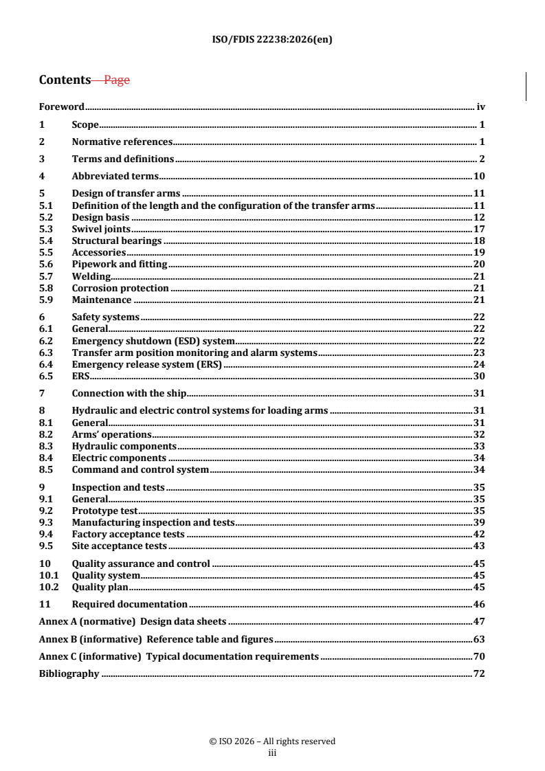
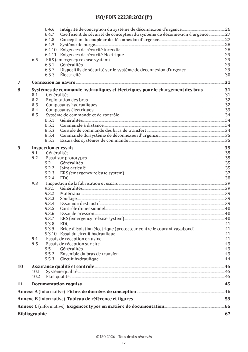
Contents Page
Foreword .v
1 Scope . 1
2 Normative references . 1
3 Terms and definitions . 2
4 Abbreviated terms . 9
5 Design of transfer arms . 9
5.1 Definition of the length and the configuration of the transfer arms .9
5.1.1 General .9
5.1.2 Balancing .10
5.1.3 Arms’ dimensions and clearances .10
5.2 Design basis.11
5.2.1 Product line diameter .11
5.2.2 Material and grades .11
5.2.3 Stress analysis . 12
5.3 Swivel joints . 15
5.3.1 General . 15
5.3.2 Product sealing arrangement . 15
5.3.3 External sealing arrangement. 15
5.3.4 Design . 15
5.4 Structural bearings .16
5.4.1 Design .16
5.4.2 Protection of structural bearings .17
5.4.3 Grease sampling point .17
5.5 Accessories .17
5.5.1 Adjustable support (jack) .17
5.5.2 Nitrogen injection .18
5.5.3 Stowing locking device .18
5.5.4 Access .18
5.5.5 Blowdown line .18
5.6 Pipework and fitting .18
5.6.1 Process connections .18
5.6.2 Depressurisation connection .18
5.6.3 Plugged connection .19
5.6.4 Valve .19
5.6.5 Flange connection and gaskets .19
5.7 Welding . .19
5.8 Corrosion protection .19
5.9 Maintenance .19
6 Safety systems . 19
6.1 General .19
6.2 Emergency shutdown (ESD) system . 20
6.2.1 General . 20
6.2.2 Emergency shutdown - Level I (ESD I) . 20
6.2.3 Emergency shutdown - Level II (ESD II) .21
6.3 Transfer arm position monitoring and alarm systems .21
6.3.1 Transfer arm operating envelopes .21
6.3.2 Excessive arm movement detection .21
6.4 Emergency release system (ERS) . 22
6.4.1 General . 22
6.4.2 Determination of need for emergency release function . 22
6.4.3 ERS functional blocks . 23
6.4.4 ERS actuation sequence . 23
6.4.5 ERS actuation time . 23
iii
6.4.6 ERS design integrity .24
6.4.7 ERS design safety factor . 25
6.4.8 EDC design . 25
6.4.9 Blowdown system . 26
6.4.10 Fire safety requirements . 26
6.4.11 Electrical safety requirements . 26
6.5 ERS .27
6.5.1 General .27
6.5.2 Safety devices on ERS .27
6.5.3 Electrical.27
7 Connection with the ship .28
8 Hydraulic and electric control systems for loading arms .28
8.1 General . 28
8.2 Arms’ operations . 29
8.3 Hydraulic components . 29
8.4 Electric components .31
8.5 Command and control system .31
8.5.1 General .31
8.5.2 Remote control .31
8.5.3 Transfer arms control console .31
8.5.4 ERS control .32
8.5.5 Testing of control systems .32
9 Inspection and tests .32
9.1 General .32
9.2 Prototype test .32
9.2.1 General .32
9.2.2 Swivel joint .32
9.2.3 ERS . 33
9.2.4 EDC . 35
9.3 Manufacturing inspection and tests . 36
9.3.1 General . 36
9.3.2 Materials . 36
9.3.3 Welding . 36
9.3.4 Non-destructive test . 36
9.3.5 Dimensional inspection. 36
9.3.6 Pressure test . 36
9.3.7 ERS .37
9.3.8 EDC .37
9.3.9 Insulating flange (stray current protector) .37
9.3.10 Hydraulic circuit test . 38
9.4 Factory acceptance tests . 38
9.5 Site acceptance tests . 39
9.5.1 General . 39
9.5.2 Transfer arm assembly . 39
9.5.3 Hydraulic circuit . 40
10 Quality assurance and control . 41
10.1 Quality system .41
10.2 Quality plan .41
11 Required documentation . 41
Annex A (normative) Design data sheets.42
Annex B (informative) Reference table and figures .55
Annex C (informative) Typical documentation requirements .60
Bibliography .62
iv
Foreword
ISO (the International Organization for Standardization) is a worldwide federation of national standards
bodies (ISO member bodies). The work of preparing International Standards is normally carried out through
ISO technical committees. Each member body interested in a subject for which a technical committee
has been established has the right to be represented on that committee. International organizations,
governmental and non-governmental, in liaison with ISO, also take part in the work. ISO collaborates closely
with the International Electrotechnical Commission (IEC) on all matters of electrotechnical standardization.
The procedures used to develop this document and those intended for its further maintenance are described
in the ISO/IEC Directives, Part 1. In particular, the different approval criteria needed for the different types
of ISO document should be noted. This document was drafted in accordance with the editorial rules of the
ISO/IEC Directives, Part 2 (see www.iso.org/directives).
ISO draws attention to the possibility that the implementation of this document may involve the use of (a)
patent(s). ISO takes no position concerning the evidence, validity or applicability of any claimed patent
rights in respect thereof. As of the date of publication of this document, ISO had not received notice of (a)
patent(s) which may be required to implement this document. However, implementers are cautioned that
this may not represent the latest information, which may be obtained from the patent database available at
www.iso.org/patents. ISO shall not be held responsible for identifying any or all such patent rights.
Any trade name used in this document is information given for the convenience of users and does not
constitute an endorsement.
For an explanation of the voluntary nature of standards, the meaning of ISO specific terms and expressions
related to conformity assessment, as well as information about ISO's adherence to the World Trade
Organization (WTO) principles in the Technical Barriers to Trade (TBT), see www.iso.org/iso/foreword.html.
This document was prepared by Technical Committee ISO/TC 67, Oil and gas industries including lower carbon
energy, Subcommittee SC 9, Production, transport and storage facilities for cryogenic liquefied gases.
Any feedback or questions on this document should be directed to the user’s national standards body. A
complete listing of these bodies can be found at www.iso.org/members.html.
v
FINAL DRAFT International Standard ISO/FDIS 22238:2026(en)
Design, construction and testing of high-pressure natural gas
marine transfer arms
1 Scope
This document specifies the design, minimum safety requirements and inspection and testing procedures
for high-pressure natural gas (HPNG) marine transfer arms intended for floating storage and regasification
unit (FSRU), floating regasification unit (FRU) and floating storage unit (FSU) applications. High-pressure
transfer arms are considered to be ship-to-shore systems transferring pressurized gas from floating units
to any part of a gas grid.
This document provides the requirements for power or control systems, but it does not include all the details
for the design and fabrication of standard parts and fittings associated with transfer arms.
This document supplements the requirements of ISO 28460.
This document is applicable to general electrical-hydraulic systems. It can be applied to other control
systems, for example, using only electrical or other power supplies, if they meet the functional safety and
performance requirements of Clause 8 for the hydraulic and electrical control systems.
This document can also be applied to existing facilities.
2 Normative references
The following referenced documents, in whole or in part, are normatively referenced in this document
and are indispensable for its application. For dated references, only the edition cited applies. For undated
references, the latest edition of the referenced document (including any amendments) applies.
ISO 3452-1, Non-destructive testing — Penetrant testing — Part 1: General principles
ISO 4406, Hydraulic fluid power — Fluids — Method for coding the level of contamination by solid particles
ISO 9934-1, Non-destructive testing — Magnetic particle testing — Part 1: General principles
ISO 10474, Steel and steel products — Inspection documents
ISO 10497, Testing of valves — Fire type-testing requirements
ISO 17636-1, Non-destructive testing of welds — Radiographic testing — Part 1: X- and gamma-ray techniques
with film
ISO 17636-2, Non-destructive testing of welds — Radiographic testing — Part 2: X- and gamma-ray techniques
with digital detectors
ISO 28460:2010, Petroleum and natural gas industries — Installation and equipment for liquefied natural gas
— Ship-to-shore interface and port operations
IEC 60034-5, Rotating electrical machines — Part 5: Degrees of protection provided by the integral design of
rotating electrical machines (IP code) — Classification
IEC 60079-0, Explosive atmospheres — Part 0: Equipment — General requirements
IEC 60079-1, Explosive atmospheres — Part 1: Equipment protection by flameproof enclosures “d”
IEC 60079-2, Explosive atmospheres — Part 2: Equipment protection by pressurized enclosures “p”
IEC 60079-5, Explosive atmospheres — Part 5: Equipment protection by powder filling “q”
IEC 60079-6, Explosive atmospheres — Part 6: Equipment protection by oil immersion “o”
IEC 60079-7, Explosive atmospheres — Part 7: Equipment protection by increased safety “e”
IEC 60079-10-1, Explosive atmospheres — Part 10-1: Classification of areas — Explosive gas atmospheres
IEC 60079-11, Explosive atmospheres — Part 11: Equipment protection by intrinsic safety “i”
IEC 60079-14, Explosive atmospheres — Part 14: Electrical installations design, selection and erection
IEC 60079-18, Explosive atmospheres — Part 18: Equipment protection by encapsulation “m”
IEC 60079-25, Explosive atmospheres — Part 25: Intrinsically safe electrical systems
IEC 60529, Degrees of protection provided by enclosures (IP Code) and IEC 60529/A1&A2, Amendment 1&2
IEC 61508 (all parts), Functional safety of electrical/electronic/programmable electronic safety-related systems
IEC 61511, Functional Safety — Safety Instrumented Systems for the Process Industry Sector
IEC 62305-3, Protection against lightning — Part 3: Physical damage to structures and life hazard
ASME B16.5, Pipe Flanges and Flanged Fittings
ASME Boiler and Pressure Vessel Code Section IX, Welding and Brazing Qualifications
3 Terms and definitions
For the purposes of this document, the following terms and definitions apply.
ISO and IEC maintain terminology databases for use in standardization at the following addresses:
— ISO Online browsing platform: available at https:// www .iso .org/ obp
— IEC Electropedia: available at https:// www .electropedia .org/
3.1
apex swivel
articulated, fluid-carrying joint located between the inboard arm (3.20) and outboard arm (3.31)
Note 1 to entry: See Figures B.2 and B.3.
Note 2 to entry: It provides luffing (3.25) of the outboard arm relative to the inboard arm.
3.2
attitude
mode of use or location of the transfer arms (3.56) (i.e. manoeuvring, stowed, connected, hydrostatic test,
and maintenance)
Note 1 to entry: The transfer arm can take several positions for each attitude.
3.3
base riser
standpost
vertical assembly which bolts to the loading platform and supports the articulated assembly of the transfer
arm (3.56)
Note 1 to entry: See Figures B.2 and B.3.
3.4
bottom swivel
swivel that accommodates the pitch (3.34) of a vessel (3.60) and is located adjacent to the presentation flange
(3.36) in the horizontal part of a TSA (3.57)
Note 1 to entry: See Figures B.2 and B.3.
3.5
brinelling
permanent indentation in swivel or structural bearing (3.48) raceways caused by excessive loading of balls
or rollers
Note 1 to entry: See Figures B.2 and B.3.
3.6
clash
contact during operational conditions, or as a result of an emergency separation, between any part of a
transfer arm (3.56) and:
— adjacent transfer arm while both arms are operating or one arm is operating and the other arm is stowed
[e.g. the counterweights (3.8)];
— adjacent section of the same transfer arms [e.g. triple swivel assembly (3.57) and outboard arm (3.31)];
— loading platform equipment [e.g. counterweight and piping or valves]
3.7
contact angle
α
angle between the plane of the swivel joint (3.53) or structural bearing (3.48) balls or rollers and the centre
of contact at the ball or roller raceway interface
3.8
counterweight
system of weights used to balance the inboard arm (3.20) and outboard arm (3.31) assemblies
3.9
design pressure
pressure for which the transfer arm (3.56) is designed
Note 1 to entry: See Table A.1.
3.10
design temperature
range of temperatures for which the transfer arm (3.56) is designed
Note 1 to entry: See Table A.1.
3.11
drift
longitudinal and/or lateral displacement of the vessel (3.60) under the influence of environmental forces
Note 1 to entry: See also surge fore (3.50) or surge aft (3.49) and sway (3.52).
3.12
emergency disconnection coupler
EDC
hydraulic, mechanical device used to release the transfer arm (3.56) from the vessel (3.60)
Note 1 to entry: The EDC is a part of the emergency release system (3.13).
Note 2 to entry: See Figure B.3.
3.13
emergency release system
ERS
system that provides a positive means of quick release of transfer arm (3.56) and safe isolation between the
vessel (3.60) and shore, following a predefined procedure including an emergency shutdown (ESD) (3.14)
Note 1 to entry: See Figure B.2.
3.14
emergency shutdown
ESD
method that safely and effectively stops the transfer (3.55) of high-pressure natural gas (3.18) between the
vessel (3.60) and shore
3.15
freeboard
vertical distance between the ship's deck and the water level at the manifold location
Note 1 to entry: See Table A.3 and Figure A.1.
3.16
free wheel
ability of a transfer arm (3.56) when connected to a vessel (3.60) to follow the vertical and horizontal motions
of the vessel manifold (3.61) freely without restraint (draft changes and sway (3.52) and surge motions)
3.17
heave
vertical motion of the vessel (3.60) due to wave action
Note 1 to entry: See Table A.4 and Figure A.2.
3.18
high-pressure natural gas
HPNG
gas contained within the transfer system at a working pressure (3.62) exceeding 10 barg
Note 1 to entry: Gas above this pressure threshold can contain sufficient stored compressible energy to require
controlled depressurization (blowdown) prior to emergency release system (3.13) disconnection. Pressures below this
threshold, such as typical low-pressure vapor return service, are not considered high-pressure for the purpose of ERS
and blowdown requirements
3.19
hydraulic power unit
HPU
unit that generates hydraulic power to ensure the normal operation and emergency release sequence of the
systems
3.20
inboard arm
product-carrying pipe and any structural members contained between the apex swivel (3.1) and the trunnion
swivel (3.58)
Note 1 to entry: See Figures B.2 and B.3.
3.21
included angle
angle formed between inboard arm (3.20) and outboard arm (3.31)
Note 1 to entry: See Figures B.2 and B.3.
Note 2 to entry: The maximum and minimum included angles are left to the transfer arm (3.56) manufacturer.
Note 3 to entry: The included angle in the stowed position of the transfer arms is such, that the arms are parked with
the triple swivel assembly (3.57) behind the berthing line.
3.22
insulating flange
electrical insulating system, usually dedicated, which is installed in the lower end of the outboard arm (3.31)
or in the vertical part of the triple swivel assembly (3.57)
Note 1 to entry: Its purpose is to prevent stray currents from causing an arc at the vessel’s (3.60) flange as the transfer
arm (3.56) is connected or disconnected.
3.23
jack
permanent, adjustable load-carrying mechanism potentially installed in the triple swivel assembly (3.57) to
transfer loads or momentum to the deck instead of the vessel manifold (3.61)
Note 1 to entry: See Figures B.2 and B.3.
3.24
lowest anticipated service temperature
LAST
reference temperature based on ambient and process conditions
3.25
luffing
rotary motion of the inboard arm (3.20) and outboard arm (3.31) in the vertical plane
Note 1 to entry: See Figures B.2 and B.3.
3.26
manifold connection unit
MCU
special spool piece (3.45) with ship-side ERS (3.13) valve for horizontal orientation or special connection
frame with elbow, swivel joint and ERS valve for vertical orientation
3.27
manifold setback
horizontal distance between the vessel’s (3.60) side and the face of vessel manifold (3.61)
Note 1 to entry: See Table A.3 and Figure A.1.
3.28
manifold spacing
horizontal distance between two adjacent vessel manifold (3.61) flange axes
Note 1 to entry: See Table A.3 and Figure A.1.
3.29
middle swivel
swivel that accommodates the yaw (3.63) and surge of a vessel (3.60) and is located between the top swivel
(3.54) and the bottom swivel (3.4) in the vertical part of a TSA (3.57)
Note 1 to entry: See Figures B.2 and B.3.
3.30
operating envelope
space in which presentation flange(s) (3.36) of a (group of) transfer arms (3.56) is (are) required to operate
in all directions
3.31
outboard arm
product-carrying pipe and any structural members contained between the apex swivel (3.1) and the triple
swivel assembly (3.57)
Note 1 to entry: See Figures B.2 and B.3.
3.32
owner
company or group of companies for whose use the transfer arms (3.56) are installed, responsible for the safe
design and construction of the installation
3.33
pantograph system
system for transmitting balancing loads from the outboard arm (3.31) to the counterweight(s) (3.8)
Note 1 to entry: The system comprises an assembly of linkages and pinned connections, or a cable and sheaves system
(respectively, “rigid link pantograph” and “cables and sheaves pantograph”).
3.34
pitch
rotation of the vessel (3.60) around the transversal horizontal axis
Note 1 to entry: See Table A.4 and Figure A.2.
3.35
powered emergency release coupling
PERC
powered device to provide a means of quick release of the transfer arm (3.56) when such action is required
only as an emergency measure
3.36
presentation flange
transfer arm (3.56) flange for connection to either the vessel manifold (3.61) or spool piece (3.45)
Note 1 to entry: See Figures B.2 and B.3.
3.37
product
high-pressure natural gas (3.18) transferred using transfer arm (3.56)
3.38
remote control
device to facilitate the fine manoeuvring operation of the transfer arms (3.56) from a remote location, e.g.
vessel manifold (3.61) area
Note 1 to entry: The system can use a trailing wire (pendant) and/or radio-controlled system.
3.39
riser and trunnion swivel assembly
gas-carrying system consisting of a riser swivel (3.41), a trunnion swivel (3.58) and elbows mounted on top of
the base riser (3.3)
Note 1 to entry: See Figures B.2 and B.3.
3.40
riser flange
transfer arm (3.56) flange for connection to shore-side piping
Note 1 to entry: See Figures B.2 and B.3.
3.41
riser swivel
swivel joint in the riser and trunnion swivel assembly (3.39) which permits slew (3.44) of the transfer arms
(3.56)
Note 1 to entry: See Figures B.2 and B.3.
3.42
roll
rotation of vessel (3.60) around the longitudinal horizontal axis
Note 1 to entry: See Table A.4 and Figure A.2.
3.43
safety integrity level
SIL
level of integrity required of a safety-related system
Note 1 to entry: Safety-related systems shall be in accordance with the IEC 61508 series.
Note 2 to entry: See Clause 6.
3.44
slew
horizontal, rotary motion of the transfer arm (3.56) around the base riser (3.3)
Note 1 to entry: See Figures B.2 and B.3.
3.45
spool piece
adaptor
short distance piece
short length of pipe for the purpose of matching the vessel manifold (3.61) to the presentation flange (3.36)
3.46
spotting line
pre-determined location on the jetty used by the vessel (3.60) when berthing to align the vessel manifold(s)
(3.61)
Note 1 to entry: See Figure A.4.
3.47
stress analysis
detailed calculation of the structural loading in the transfer arm (3.56) and vessel manifold (3.61) for various
positions and attitudes (3.2) to check the integrity of the transfer arm for the service intended
3.48
structural bearing
bearing in the load carrying components supporting the product (3.37) line that, in combination, allow the
transfer arm (3.56) to follow freely the motion of the vessel (3.60)
3.49
surge aft
longitudinal vessel (3.60) afterward motion
Note 1 to entry: See Table A.4 and Figure A.2.
3.50
surge fore
longitudinal vessel (3.60) forward motion
Note 1 to entry: See Table A.4 and Figure A.2.
3.51
pressure surge
rapid change in pressure as a consequence of a change in flow rate in a pipeline and/or piping systems,
including transfer arm (3.56)
3.52
sway
transverse vessel (3.60) motion
Note 1 to entry: See Table A.4 and Figure A.2.
3.53
swivel
swivel joint
rotating connection contained in the transfer arm (3.56) to permit the arm/system to follow freely the
motion of the vessel (3.60)
3.54
top swivel
swivel that accommodates the roll (3.42), heave (3.17) and sway (3.52) of a vessel (3.60) and is located
between the outboard arm (3.31) and the middle swivel (3.29) in the horizontal part of a TSA (3.57)
Note 1 to entry: See Figures B.2 and B.3.
3.55
transfer
transmission of high-pressure natural gas (3.18) from the vessel (3.60) to any fixed part of a harbour or
coastal locations
3.56
transfer arm
articulated mechanical system used for transmission of a product (3.37) from vessel (3.60) with the
capability of accommodating differences in tides, freeboard (3.15) and vessel’s motions
Note 1 to entry: See Figures B.2 and B.3.
3.57
triple swivel assembly
TSA
group of three swivels (3.53) and elbows located at the end of the outboard arm (3.31)
Note 1 to entry: See Figures B.2 and B.3.
3.58
trunnion swivel
swivel joint in the riser and trunnion swivel assembly (3.39) which permits the inboard arm (3.20) to rotate
around the horizontal or vertical axis
Note 1 to entry: See Figures B.2 and B.3.
3.59
UPS
uninterrupted power supply
back-up of the electrical supply system providing power to critical control and safety systems so that the
plant can be kept in safe conditions
3.60
vessel
floating unit for the storage and/ or regasification of LNG and for sending out high-pressure natural gas (3.18)
(also known as FSRU/FSU/FRU)
3.61
vessel manifold
pipe assembly mounted onboard vessel (3.60) to which the presentation flange (3.36) or spool piece (3.45) of
the transfer arm (3.56) is connected
3.62
working pressure
maximum internal pressure that a transfer system is designed to operate under during normal, steady-state
service, including all expected process variations but excluding short-duration pressure transients
associated with start-up, shutdown, or abnormal conditions
3.63
yaw
rotation of the vessel (3.60) around the vertical axis
Note 1 to entry: See Table A.4 and Figure A.2.
4 Abbreviated terms
CPMS constant position monitoring system
EMC electro-magnetic compatibility
FL fluid load
FMEDA failure mode and effects analysis
HP high pressure
LNG liquefied natural gas
N nitrogen gas
OBE operating basis earthquake
OEM original equipment manufacturer
PL pressure load
PQR performance quality records
SSE safe shutdown earthquake
TL thermal load
WL wind load
WPS welding procedure specifications
ρ density
v velocity
5 Design of transfer arms
5.1 Definition of the length and the configuration of the transfer arms
5.1.1 General
The general arrangement of the transfer arm is shown in Annex B (see Figures B.2 and B.3).
The length and the configuration of the transfer arms shall allow for the connection of the on-shor
...
ISO/TC 67/SC 9
Date: 2026-06-16
Secretariat: AFNOR
Oil and gas industries including lower carbon energy —
Date: 2026-08-14
Design, construction and testing of high-pressure natural gas marine
transfer arms
Conception, construction et essais de bras de transfert maritimemarins de gaz naturel à haute pression
FDIS stage
All rights reserved. Unless otherwise specified, or required in the context of its implementation, no part of this publication
may be reproduced or utilized otherwise in any form or by any means, electronic or mechanical, including photocopying,
or posting on the internet or an intranet, without prior written permission. Permission can be requested from either ISO
at the address below or ISO'sISO’s member body in the country of the requester.
ISO Copyright Officecopyright office
CP 401 • Ch. de Blandonnet 8
CH-1214 Vernier, Geneva
Phone: + 41 22 749 01 11
Email: E-mail: copyright@iso.org
Website: www.iso.org
Published in Switzerland.
ii
Contents Page
Foreword . iv
1 Scope . 1
2 Normative references . 1
3 Terms and definitions . 2
4 Abbreviated terms . 10
5 Design of transfer arms . 11
5.1 Definition of the length and the configuration of the transfer arms . 11
5.2 Design basis . 12
5.3 Swivel joints . 17
5.4 Structural bearings . 18
5.5 Accessories . 19
5.6 Pipework and fitting . 20
5.7 Welding . 21
5.8 Corrosion protection . 21
5.9 Maintenance . 21
6 Safety systems . 22
6.1 General. 22
6.2 Emergency shutdown (ESD) system . 22
6.3 Transfer arm position monitoring and alarm systems . 23
6.4 Emergency release system (ERS) . 24
6.5 ERS . 30
7 Connection with the ship . 31
8 Hydraulic and electric control systems for loading arms . 31
8.1 General. 31
8.2 Arms’ operations . 32
8.3 Hydraulic components . 33
8.4 Electric components . 34
8.5 Command and control system . 34
9 Inspection and tests . 35
9.1 General. 35
9.2 Prototype test . 35
9.3 Manufacturing inspection and tests . 39
9.4 Factory acceptance tests . 42
9.5 Site acceptance tests . 43
10 Quality assurance and control . 45
10.1 Quality system . 45
10.2 Quality plan . 45
11 Required documentation . 46
Annex A (normative) Design data sheets . 47
Annex B (informative) Reference table and figures . 63
Annex C (informative) Typical documentation requirements . 70
Bibliography . 72
iii
Foreword
ISO (the International Organization for Standardization) is a worldwide federation of national standards
bodies (ISO member bodies). The work of preparing International Standards is normally carried out through
ISO technical committees. Each member body interested in a subject for which a technical committee has been
established has the right to be represented on that committee. International organizations, governmental and
non-governmental, in liaison with ISO, also take part in the work. ISO collaborates closely with the
International Electrotechnical Commission (IEC) on all matters of electrotechnical standardization.
The procedures used to develop this document and those intended for its further maintenance are described
in the ISO/IEC Directives, Part 1. In particular, the different approval criteria needed for the different types of
ISO document should be noted. This document was drafted in accordance with the editorial rules of the
ISO/IEC Directives, Part 2 (see www.iso.org/directives).
ISO draws attention to the possibility that the implementation of this document may involve the use of (a)
patent(s). ISO takes no position concerning the evidence, validity or applicability of any claimed patent rights
in respect thereof. As of the date of publication of this document, ISO had not received notice of (a) patent(s)
which may be required to implement this document. However, implementers are cautioned that this may not
represent the latest information, which may be obtained from the patent database available at
www.iso.org/patents. ISO shall not be held responsible for identifying any or all such patent rights.
Any trade name used in this document is information given for the convenience of users and does not
constitute an endorsement.
For an explanation of the voluntary nature of standards, the meaning of ISO specific terms and expressions
related to conformity assessment, as well as information about ISO's adherence to the World Trade
Organization (WTO) principles in the Technical Barriers to Trade (TBT), see www.iso.org/iso/foreword.html.
This document was prepared by Technical Committee ISO/TC 67, Oil and gas industries including lower carbon
energy, Subcommittee SC 9, Production, transport and storage facilities for cryogenic liquefied gases.
Any feedback or questions on this document should be directed to the user’s national standards body. A
complete listing of these bodies can be found at www.iso.org/members.html.
iv
Design, construction and testing of high-pressure natural gas marine
transfer arms
1 Scope
This document specifies the design, minimum safety requirements and inspection and testing procedures for
high-pressure natural gas (HPNG) marine transfer arms intended for floating storage and regasification unit
(FSRU) /), floating regasification unit (FRU) /and floating storage unit (FSU) applications. High-pressure
transfer arms are considered to be ship-to-shore systems transferring pressurized gas from floating units to
any part of a gas grid.
This document provides the requirements for power or control systems, but it does not include all the details
for the design and fabrication of standard parts and fittings associated with transfer arms.
This document supplements the requirements of ISO 28460.
This document is applicable to general electrical-hydraulic systems. It can be applied to other control systems,
for example, using only electrical or other power supplies, if they meet the functional safety and performance
requirements of Clause 8Clause 8 for the hydraulic and electrical control systems.
This document can also be applied to existing facilities.
2 Normative references
The following referenced documents, in whole or in part, are normatively referenced in this document and are
indispensable for its application. For dated references, only the edition cited applies. For undated references,
the latest edition of the referenced document (including any amendments) applies.
ISO 3452--1, Non-destructive testing — Penetrant testing — Part 1: General principles
ISO 4406, Hydraulic fluid power — Fluids — Method for coding the level of contamination by solid particles
ISO 9934--1, Non-destructive testing — Magnetic particle testing — Part 1: General principles
ISO 10474, Steel and steel products — Inspection documents
ISO 10497, Testing of valves — Fire type-testing requirements
ISO 17636--1, Non-destructive testing of welds — Radiographic testing — Part 1: X- and gamma-ray techniques
with film
ISO 17636--2, Non-destructive testing of welds — Radiographic testing — Part 2: X- and gamma-ray techniques
with digital detectors
ISO 28460:2010, Petroleum and natural gas industries — Installation and equipment for liquefied natural gas
— Ship-to-shore interface and port operations
IEC 60034--5, Rotating electrical machines — Part 5: Degrees of protection provided by the integral design of
rotating electrical machines (IP code) — Classification
IEC 60079--0, Explosive atmospheres — Part 0: Equipment — General requirements
IEC 60079--1, Explosive atmospheres — Part 1: Equipment protection by flameproof enclosures “d”
IEC 60079--2, Explosive atmospheres — Part 2: Equipment protection by pressurized enclosures “p”
IEC 60079--5, Explosive atmospheres — Part 5: Equipment protection by powder filling “q”
IEC 60079--6, Explosive atmospheres — Part 6: Equipment protection by oil immersion “o”
IEC 60079--7, Explosive atmospheres — Part 7: Equipment protection by increased safety “e”
IEC 60079--10--1, Explosive atmospheres — Part 10-1: Classification of areas — Explosive gas atmospheres
IEC 60079--11, Explosive atmospheres — Part 11: Equipment protection by intrinsic safety “i”
IEC 60079--14, Explosive atmospheres — Part 14: Electrical installations design, selection and erection
IEC 60079--18, Explosive atmospheres — Part 18: Equipment protection by encapsulation “m”
IEC 60079--25, Explosive atmospheres — Part 25: Intrinsically safe electrical systems
IEC 60529, Degrees of protection provided by enclosures (IP Code) and IEC 60529/A1&A2, Amendment 1&2
IEC 61508 (all parts), Functional safety of electrical/electronic/programmable electronic safety-related systems
IEC 61511, Functional Safety -— Safety Instrumented Systems for the Process Industry Sector
IEC 62305--3, Protection against lightning — Part 3: Physical damage to structures and life hazard
ASME B16.5, Pipe Flanges and Flanged Fittings
ASME Boiler and Pressure Vessel Code Section IX, Welding and Brazing Qualifications
3 Terms and definitions
For the purposes of this document, the following terms and definitions apply.
ISO and IEC maintain terminology databases for use in standardization at the following addresses:
— — ISO Online browsing platform: available at https://www.iso.org/obp
— — IEC Electropedia: available at https://www.electropedia.org/
3.1 3.1
apex swivel
articulated, fluid-carrying joint located between the inboard arm (3.20(3.20)) and outboard arm (3.31(3.31))
Note 1 to entry: See Figures B.2Figures B.2 and B.3B.3.
Note 2 to entry: It provides luffing (3.25(3.25)) of the outboard arm relative to the inboard arm.
3.2 3.2
attitude
mode of use or location of the transfer arms (3.56(3.56)) (i.e. manoeuvring, stowed, connected, hydrostatic
test, and maintenance)
Note 1 to entry: The transfer arm can take several positions for each attitude.
3.3 3.3
base riser
standpost
vertical assembly which bolts to the loading platform and supports the articulated assembly of the transfer
arm (3.56(3.56))
Note 1 to entry: See Figures B.2Figures B.2 and B.3B.3.
3.4 3.4
bottom swivel
swivel that accommodates the pitch (3.34(3.34)) of a vessel (3.60(3.60)) and is located adjacent to the
presentation flange (3.36(3.36)) in the horizontal part of a TSA (3.57(3.57))
Note 1 to entry: See Figures B.2Figures B.2 and B.3B.3.
3.5 3.5
brinelling
permanent indentation in swivel or structural bearing (3.48(3.48)) raceways caused by excessive loading of
balls or rollers
Note 1 to entry: See Figures B.2Figures B.2 and B.3B.3.
3.6 3.6
clash
contact during operational conditions, or as a result of an emergency separation, between any part of a transfer
arm (3.56(3.56)) and:
— — adjacent transfer arm while both arms are operating or one arm is operating and the other arm is
stowed [e.g. the counterweights (3.8(3.8)];)];
— — adjacent section of the same transfer arms [e.g. triple swivel assembly (3.57(3.57)) and outboard arm
(3.31(3.31)];)];
— — loading platform equipment [e.g. counterweight and piping or valves]
3.7 3.7
contact angle
α
angle between the plane of the swivel joint (3.53(3.53)) or structural bearing (3.48(3.48)) balls or rollers and
the centre of contact at the ball or roller raceway interface
3.8 3.8
counterweight
system of weights used to balance the inboard arm (3.20(3.20)) and outboard arm (3.31(3.31)) assemblies
3.9 3.9
design pressure
pressure for which the transfer arm (3.56(3.56)) is designed
Note 1 to entry: See Table A.1Table A.1.
3.10 3.10
design temperature
range of temperatures for which the transfer arm (3.56(3.56)) is designed
Note 1 to entry: See Table A.1Table A.1.
3.11 3.11
drift
longitudinal and/or lateral displacement of the vessel (3.60(3.60)) under the influence of environmental forces
Note 1 to entry: See also surge fore (3.50(3.50)) or surge aft (3.49(3.49)) and sway (3.52(3.52).).
3.12 3.12
emergency disconnection coupler
EDC
hydraulic, mechanical device used to release the transfer arm (3.56(3.56)) from the vessel (3.60(3.60))
Note 1 to entry: The EDC is a part of the emergency release system (3.13(3.13).).
Note 2 to entry: See Figure B.3Figure B.3.
3.13 3.13
emergency release system
ERS
system that provides a positive means of quick release of transfer arm (3.56(3.56)) and safe isolation between
the vessel (3.60(3.60)) and shore, following a predefined procedure including an emergency shutdown (ESD)
(3.14(3.14))
Note 1 to entry: See Figure B.2Figure B.2.
3.14 3.14
emergency shutdown
ESD
method that safely and effectively stops the transfer (3.55(3.55)) of high-pressure natural gas (3.18(3.18))
between the vessel (3.60(3.60)) and shore
3.15 3.15
freeboard
vertical distance between the ship's deck and the water level at the manifold location
Note 1 to entry: See Table A.3Table A.3 and Figure A.1Figure A.1.
3.16 3.16
free wheel
ability of a transfer arm (3.56(3.56)) when connected to a vessel (3.60(3.60)) to follow the vertical and
horizontal motions of the vessel manifold (3.61(3.61)) freely without restraint (draft changes and sway
(3.52(3.52)) and surge motions)
3.17 3.17
heave
vertical motion of the vessel (3.60(3.60)) due to wave action
Note 1 to entry: See Table A.4Table A.4 and Figure A.2Figure A.2.
3.18 3.18
high-pressure natural gas
HPNG
Gasgas contained within the transfer system at a working pressure (3.62(3.62)) exceeding 10 barg. 10 barg
Note 1 to entry: Gas above this pressure threshold may containscan contain sufficient stored compressible energy to
require controlled depressurization (blowdown) prior to emergency release system (3.13(3.13)) disconnection.
Pressures below this threshold, such as typical low--pressure vapor return service, are not considered high--pressure for
the purpose of ERS and blowdown requirements
3.19 3.19
hydraulic power unit
HPU
unit that generates hydraulic power to ensure the normal operation and emergency release sequence of the
systems
3.20 3.20
inboard arm
product-carrying pipe and any structural members contained between the apex swivel (3.1(3.1)) and the
trunnion swivel (3.58(3.58))
Note 1 to entry: See Figures B.2Figures B.2 and B.3B.3.
3.21 3.21
included angle
angle formed between inboard arm (3.20(3.20)) and outboard arm (3.31(3.31))
Note 1 to entry: See Figures B.2Figures B.2 and B.3B.3.
Note 2 to entry: The maximum and minimum included angles are left to the transfer arm (3.56(3.56)) manufacturer.
Note 3 to entry: The included angle in the stowed position of the transfer arms is such, that the arms are parked with the
triple swivel assembly (3.57(3.57)) behind the berthing line.
3.22 3.22
insulating flange
electrical insulating system, usually dedicated, which is installed in the lower end of the outboard arm
(3.31(3.31)) or in the vertical part of the triple swivel assembly (3.57(3.57))
Note 1 to entry: Its purpose is to prevent stray currents from causing an arc at the vessel’s (3.60(3.60)) flange as the
transfer arm (3.56(3.56)) is connected or disconnected.
3.23 3.23
jack
permanent, adjustable load-carrying mechanism potentially installed in the triple swivel assembly (3.57(3.57))
to transfer loads or momentum to the deck instead of the vessel manifold (3.61(3.61))
Note 1 to entry: See Figures B.2Figures B.2 and B.3B.3.
3.24 3.24
lowest anticipated service temperature
LAST
reference temperature based on ambient and process conditions
3.25 3.25
luffing
rotary motion of the inboard arm (3.20(3.20)) and outboard arm (3.31(3.31)) in the vertical plane
Note 1 to entry: See Figures B.2Figures B.2 and B.3B.3.
3.26 3.26
manifold connection unit
MCU
special spool piece (3.45(3.45)) with ship-side ERS (3.13(3.13)) valve for horizontal orientation or special
connection frame with elbow, swivel joint and ERS valve for vertical orientation
3.27 3.27
manifold setback
horizontal distance between the vessel’s (3.60(3.60)) side and the face of vessel manifold (3.61(3.61))
Note 1 to entry: See Table A.3Table A.3 and Figure A.1Figure A.1.
3.28 3.28
manifold spacing
horizontal distance between two adjacent vessel manifold (3.61(3.61)) flange axes
Note 1 to entry: See Table A.3Table A.3 and Figure A.1Figure A.1.
3.29 3.29
middle swivel
swivel that accommodates the yaw (3.63(3.63)) and surge of a vessel (3.60(3.60)) and is located between the
top swivel (3.54(3.54)) and the bottom swivel (3.4(3.4)) in the vertical part of a TSA (3.57(3.57))
Note 1 to entry: See Figures B.2Figures B.2 and B.3B.3.
3.30 3.30
operating envelope
space in which presentation flange(s) (3.36(3.36)) of a (group of) transfer arms (3.56(3.56)) is (are) required
to operate in all directions
3.31 3.31
outboard arm
product-carrying pipe and any structural members contained between the apex swivel (3.1(3.1)) and the triple
swivel assembly (3.57(3.57))
Note 1 to entry: See Figures B.2Figures B.2 and B.3B.3.
3.32 3.32
owner
company or group of companies for whose use the transfer arms (3.56(3.56)) are installed, responsible for the
safe design and construction of the installation
3.33 3.33
pantograph system
system for transmitting balancing loads from the outboard arm (3.31(3.31)) to the counterweight(s) (3.8(3.8))
Note 1 to entry: The system comprises an assembly of linkages and pinned connections, or a cable and sheaves system
(respectively, “rigid link pantograph” and “cables and sheaves pantograph”).
3.34 3.34
pitch
rotation of the vessel (3.60(3.60)) around the transversal horizontal axis
Note 1 to entry: See Table A.4Table A.4 and Figure A.2Figure A.2.
3.35 3.35
powered emergency release coupling
PERC
powered device to provide a means of quick release of the transfer arm (3.56(3.56)) when such action is
required only as an emergency measure
3.36 3.36
presentation flange
transfer arm (3.56(3.56)) flange for connection to either the vessel manifold (3.61(3.61)) or spool piece
(3.45(3.45))
Note 1 to entry: See Figures B.2Figures B.2 and B.3B.3.
3.37 3.37
product
high-pressure natural gas (3.18(3.18)) transferred using transfer arm (3.56(3.56))
3.38 3.38
remote control
device to facilitate the fine manoeuvring operation of the transfer arms (3.56(3.56)) from a remote location [,
e.g. vessel manifold (3.61(3.61)) area]
Note 1 to entry: The system can use a trailing wire (pendant) and/or radio-controlled system.
3.39 3.39
riser and trunnion swivel assembly
gas-carrying system consisting of a riser swivel (3.41(3.41),), a trunnion swivel (3.58(3.58)) and elbows
mounted on top of the base riser (3.3(3.3))
Note 1 to entry: See Figures B.2Figures B.2 and B.3B.3.
3.40 3.40
riser flange
transfer arm (3.56(3.56)) flange for connection to shore-side piping
Note 1 to entry: See Figures B.2Figures B.2 and B.3B.3.
3.41 3.41
riser swivel
swivel joint in the riser and trunnion swivel assembly (3.39(3.39)) which permits slew (3.44(3.44)) of the
transfer arms (3.56(3.56) )
Note 1 to entry: See Figures B.2Figures B.2 and B.3B.3.
3.42 3.42
roll
rotation of vessel (3.60(3.60)) around the longitudinal horizontal axis
Note 1 to entry: See Table A.4Table A.4 and Figure A.2Figure A.2.
3.43 3.43
safety integrity level
SIL
level of integrity required of a safety-related system
Note 1 to entry: Safety-related systems shall be in accordance with the IEC 61508 series.
Note 2 to entry: See Clause 6Clause 6.
3.44 3.44
slew
horizontal, rotary motion of the transfer arm (3.56(3.56)) around the base riser (3.3(3.3))
Note 1 to entry: See Figures B.2Figures B.2 and B.3B.3.
3.45 3.45
spool piece
adaptor
short distance piece
short length of pipe for the purpose of matching the vessel manifold (3.61(3.61)) to the presentation flange
(3.36(3.36))
3.46 3.46
spotting line
pre-determined location on the jetty used by the vessel (3.60(3.60)) when berthing to align the vessel
manifold(s) (3.61(3.61))
Note 1 to entry: See Figure A.4Figure A.4.
3.47 3.47
stress analysis
detailed calculation of the structural loading in the transfer arm (3.56(3.56)) and vessel manifold (3.61(3.61))
for various positions and attitudes (3.2(3.2)) to check the integrity of the transfer arm for the service intended
3.48 3.48
structural bearing
bearing in the load carrying components supporting the product (3.37(3.37)) line that, in combination, allow
the transfer arm (3.56(3.56)) to follow freely the motion of the vessel (3.60(3.60))
3.49 3.49
surge aft
longitudinal vessel (3.60(3.60)) afterward motion
Note 1 to entry: See Table A.4Table A.4 and Figure A.2Figure A.2.
3.50 3.50
surge fore
longitudinal vessel (3.60(3.60)) forward motion
Note 1 to entry: See Table A.4Table A.4 and Figure A.2Figure A.2.
3.51 3.51
pressure surge
rapid change in pressure as a consequence of a change in flow rate in a pipeline and/or piping systems [,
including transfer arm (3.56(3.56)])
3.52 3.52
sway
transverse vessel (3.60(3.60)) motion
Note 1 to entry: See Table A.4Table A.4 and Figure A.2Figure A.2.
3.53 3.53
swivel
swivel joint
rotating connection contained in the transfer arm (3.56(3.56)) to permit the arm/system to follow freely the
motion of the vessel (3.60(3.60))
3.54 3.54
top swivel
swivel that accommodates the roll (3.42(3.42),), heave (3.17(3.17)) and sway (3.52(3.52)) of a vessel
(3.60(3.60)) and is located between the outboard arm (3.31(3.31)) and the middle swivel (3.29(3.29)) in the
horizontal part of a TSA (3.57(3.57))
Note 1 to entry: See Figures B.2Figures B.2 and B.3B.3.
3.55 3.55
transfer
transmission of high-pressure natural gas (3.18(3.18)) from the vessel (3.60(3.60)) to any fixed part of a
harbour or coastal locations
3.56 3.56
transfer arm
articulated mechanical system used for transmission of a product (3.37(3.37)) from vessel (3.60(3.60)) with
the capability of accommodating differences in tides, freeboard (3.15(3.15)) and vessel’s motions
Note 1 to entry: See Figures B.2Figures B.2 and B.3B.3.
3.57 3.57
triple swivel assembly
TSA
group of three swivels (3.53(3.53)) and elbows located at the end of the outboard arm (3.31(3.31))
Note 1 to entry: See Figures B.2Figures B.2 and B.3B.3.
3.58 3.58
trunnion swivel
swivel joint in the riser and trunnion swivel assembly (3.39(3.39)) which permits the inboard arm (3.20(3.20))
to rotate around the horizontal or vertical axis
Note 1 to entry: See Figures B.2Figures B.2 and B.3B.3.
3.59 3.59
UPS
uninterrupted power supply
back-up of the electrical supply system providing power to critical control and safety systems so that the plant
can be kept in safe conditions
3.60 3.60
vessel
floating unit for the storage and/ or regasification of LNG and for sending out high-pressure natural gas
(3.18(3.18)) (also known as FSRU/FSU/FRU)
3.61 3.61
vessel manifold
pipe assembly mounted onboard vessel (3.60(3.60)) to which the presentation flange (3.36(3.36)) or spool
piece (3.45(3.45)) of the transfer arm (3.56(3.56)) is connected
3.62 3.62
working pressure
the maximum internal pressure that a transfer system is designed to operate under during normal,
steady--state service, including all expected process variations but excluding short--duration pressure
transients associated with start--up, shutdown, or abnormal conditions
3.63 3.63
yaw
rotation of the vessel (3.60(3.60)) around the vertical axis
Note 1 to entry: See Table A.4Table A.4 and Figure A.2Figure A.2.
4 Abbreviated terms
CPMS constant position monitoring system
EMC electro-magnetic compatibility
FL fluid load
FMEDA failure mode and effects analysis
HP high pressure
LNG liquefied natural gas
N nitrogen gas
OBE operating basis earthquake
OEM original equipment manufacturer
PL pressure load
PQR performance quality records
SSE safe shutdown earthquake
TL thermal load
WL wind load
WPS welding procedure specifications
ρ density
v velocity
5 Design of transfer arms
5.1 Definition of the length and the configuration of the transfer arms
5.1.1 General
The general arrangement of the transfer arm is shown in Annex BAnnex B (see Figures B.2Figures B.2 and
B.3B.3).).
The length and the configuration of the transfer arms shall allow for the connection of the on-shore piping to
the vessel manifold. The connection shall allow for free movement within the operating envelope.
The transfer arms are normally composed of the following:
— — TSA;
— — ERS including PERC or EDC;
— — manifold connection unit mounted on-board the vessel, if required;
— — outboard arm;
— — apex swivel assembly between the outboard and inboard arm;
— — pantograph system;
— — inboard arm;
— — riser and trunnion swivel assembly between the inboard arm and the base riser;
— — base riser.
All piping supports shall be designed so that stresses in the piping and the structure are within allowable limits
for all positions.
Any parts of a transfer arm, for example, seals, bolts and nuts, shall not come off or unfasten and drop into
product piping under any circumstances.
5.1.2 Balancing
The complete TSA and outboard arm shall be balanced in the empty condition. It shall be balanced with the
pantograph system around the apex swivel.
The complete, articulated assembly shall be balanced in the empty condition. It shall be balanced around the
trunnion swivel.
In addition to normal operations, the transfer arms shall be designed to allow for the emergency release of the
arms in the both the empty and full condition. There should be no clash between the arms and any other parts
of the system, vessel or jetty.
5.1.3 Arms’ dimensions and clearances
5.1.3.1 Arms’ dimensions
Transfer arms’ dimensions shall be determined by the transfer arm manufacturer to ensure that the transfer
arms satisfy all specified requirements. For the transfer arm dimensions, the design data in Annex AAnnex A
may be used.
5.1.3.2 Clearance study
The transfer arm design shall accommodate the following minimum clearances The design shall cater for the
following minimum clearances unless otherwise specified in Table A.6Table A.6::
— — 0,15 m minimum clearance between any part of an operating arm and a stowed arm;
— — 0,3 m minimum clearance between any part of an operating arm and any adjacent structures, piping,
equipment;
— — 0,3 m minimum clearance between any part of adjacent operating arms;
— — 0,15 m minimum clearance between counterweights of operating arms.
Table B.1Table B.1 shows the locations of main clearance checkpoints.
The transfer arm manufacturer's clearance study shall include all cases including emergency release positions
and the retracting attitude following emergency release.
The study shall identify all check points, based on a drawing of the jetty layout in elevation and plan.
Consideration should be given for any future expansion.
In the stowed position, no part of the transfer arm shall extend beyond the jetty face or berthing line with
compressed fenders plus the additional safety margin corresponding to the maximum rolling angle of the
vessel (see Tables A.4, A.6Tables A.4, A.6, Figures A.2, Figures A.2 and A.3A.3).).
5.2 Design basis
5.2.1 Product line diameter
In determining the loading arm's product line diameter, the impact of flow on induced vibrations, noise and
erosion, as well as the total frictional pressure loss, should be considered. ISO 13703 provides formulae for
calculating pipe diameters (and graphs for preliminary sizing of pipe diameters). Preliminary line sizes may
need to be adjusted in accordance with good engineering judgment at later design stages.
When determining loading arm's product line diameter, the use of flow momentum (defined as ρ x v^2) should
be considered instead of velocity, as this parameter provides a more comprehensive understanding of
system's flow dynamics performance.
The maximum flow rate expected during the life of the facility should be considered, rather than the initial
flow rate. A design factor over the anticipated normal flow rate should be considered. A design factor over the
anticipated normal flow rate should be considered.
Effects of pressure surge on the transfer arm should be precisely determined by analytic methods or by pulse
pressure measurements in similar systems.
If erosion can occur, additional piping wall thickness should be considered as well as the reduction of the
maximum allowable gas flow momentum. A wall thickness monitoring method should be implemented.
The determination of the total pressure drop should include the effect of valves and fittings such as elbows or
instrumentation. Manufacturer's data or an equivalent length given in ISO 13703 may be used for valves and
fittings. Pressure loss curves for the transfer arm should be provided by the manufacturer and agreed with
the owner.
The maximum total pressure drop should determinebe determined so that the resulting end pressure,
downstream of the transfer arm, is high enough to satisfy the requirements of the next piece of equipment.
5.2.2 Material and grades
Material and grades shall have chemical, physical and mechanical properties conformable to the specified
design conditions, such as pressure, temperature, wind and earthquake loads and environment application.
Material and grades used for critical parts such as pressure containing parts including bolts and nuts and main
structural parts are subject to the owner’s approval.
The product carrying components should also take care of temperature changes due to depressurisation.
For welding purposes, the carbon content of carbon steels for structural components should not be higher
than 0,26 % except in case certified by welding procedure specifications (WPS) and performance quality
records (PQR).
Other material and grade may be considered for use if it can be demonstrated that it meets all safety and
operational performance criteria.
The grade used for the structure shall have adequate toughness and ductility at the lowest anticipated service
temperature (LAST). The same applies to parts between the product line and the structure which may be
subject to low temperatures.
5.2.3 Stress analysis
5.2.3.1 General
A complete analysis of stresses and deflections in the transfer arm and vessel manifolds shall be performed
for all appropriate arm conditions.
The calculated stresses shall be lower than or equal to the allowable design stress.
Loading combination, allowable design stress and design loads shall be in accordance with 5.2.3.25.2.3.2 to
5.2.3.95.2.3.9.
5.2.3.2 Loading combination
The transfer arm manufacturer shall prepare a stress report for the loading combinations in
Table A.15Table A.15 at all appropriate transfer arm attitudes within the envelope.
Where combinations other than those in Table A.15Table A.15 (e.g. exclusion of a load) can be shown to lead
to a greater feasible loading effect, then the design shall also allow for that condition.
Where applicable, the stress report shall also include loading effects of using any installation or maintenance
lifting lugs.
5.2.3.3 Allowable design stress
The basic allowable design stress (S ) for pressure containing and non-pressure containing structural
d
components shall be the lower of either
— — yield strength divided by 1,5, or
— — ultimate tensile strength divided by 3 for austenitic steels, and ultimate tensile strength divided by 2,4
for ferritic steels.
The yield strength and ultimate tensile strength should be the values specified in the applicable material
standards.
The allowable design stress is obtained by multiplying the basic allowable design stress with the K factor as
provided.
5.2.3.4 Pressure load
The pressure loads (P ) shall be based on design pressure.
L
5.2.3.5 Fluid load
The fluid loads (F ) shall be based on the highest density of the process medium.
L
5.2.3.6 Ice build-up
Unless otherwise specified in Table A.9Table A.9,, the dead load and wind load (D + W ) shall include ice
L L
build-up (specific gravity = 0,80) of at least 6 mm on all components in cold climate.
5.2.3.7 Thermal load
The thermal loads (T ) are the loads caused by material temperature differences. The temperature differences
L
used in the design shall be based on the design temperatures specified and the ambient and solar radiation
temperatures. These temperatures shall be applied in the most extreme combination.
5.2.3.8 Wind load
5.2.3.8.1 5.2.3.8.1 The wind loads (W ) shall be calculated for the worst direction(s). The transfer
L
arm manufacturer shall calculate wind loads as follows.
5.2.3.8.2 5.2.3.8.2 Velocity pressure
The velocity pressure is calculated as follows:
(1)
𝑞𝑞 = 0,613 ×𝐾𝐾 ×𝐾𝐾 ×𝑉𝑉 ×𝐼𝐼 (1)
z Z ZT
where
qz is the velocity pressure at height z above minimum water level (N/m );
KZ is the velocity pressure co-efficient evaluated at height Z;
KZT is the topographic factor (use 1,0);
V is the basic 3 s gust wind speed at 10 m above lowest low water (m/s);
I is the importance factor (use 1,0).
KZ is determined as follows:
(2)
(3)
2⁄𝛼𝛼
𝐾𝐾 = 2,01 × (𝑍𝑍/𝑍𝑍𝑍𝑍) for 4,6≤𝑍𝑍≤𝑍𝑍𝑍𝑍
Z
(2)
2⁄𝛼𝛼
𝐾𝐾 = 2,01 × (4,6/𝑍𝑍𝑍𝑍) for 𝑍𝑍 < 4,6
Z
(3)
where
Z is the height above low tide (m);
Z is the gradient height (m), see Table 1Table 1;;
g
α is the power law coefficient, see Table 1Table 1.
Table 1 — Exposure
Exposure α Z
g
m
C 9,5 274
D 11,5 213
Exposure C covers open terrain with scattered obstructions having heights generally less than 10 m.
Exposure D covers flat, unobstructed locations which are exposed to wind flowing over open water for a
distance of at least 1,6 km. Exposure D extends 4 000 m inland from the shoreline or 10 times the height of the
transfer arm, whichever is greater.
NOTE Exposure D is generally used for transfer arms except where exposure C can be justified.
5.2.3.8.3 5.2.3.8.3 Wind forces
The wind force is calculated as follows:
𝐹𝐹 =𝑞𝑞 ×𝐺𝐺 ×𝐶𝐶 ×𝐴𝐴 (4)
𝑧𝑧 𝑓𝑓 𝑓𝑓
where
F is the design wind force (N);
G is the gust effect factor (use 0,85);
C is the force coefficient;
f
A is the projected area normal to wind (m ).
f
The gust effect factor, G, accounts for the loading effects in the along-wind direction due to the effect of wind
turbulence on the transfer arm. It also accounts for along-wind loading due to dynamic amplification for
flexible structures. It does not include cross-wind loading effects, vortex shedding, instability or dynamic
torsional effects. If a higher value factor is justified due to dynamic sensitivity to wind, it should be determined
according to EN 1991--1--4.
The force coefficient, C , accounts for along-wind effects due to the shape or drag of the transfer arm. Transfer
f
arms are unique structures and there are no wind tunnel test data available to establish precise force
coefficients. However, based on recommendations provided in EN 1991--1--4 for round cylindrical shapes and
flat or angular shaped members, the coefficients as listed in Table 2Table 2 should be used.
Table 2 — Force coefficients
Cross-section Type of surface C
f
Round Moderately smooth 0,7
Rough 1,0
𝐷𝐷�𝑞𝑞 > 5,3
z
Round All 1,2
𝐷𝐷�𝑞𝑞 > 5,3
z
Flat or angular All 1,7
Key
D diameter (m)
qz velocity pressure at height z above minimum water level (N/m )
Alternatively, the transfer arm manufacturer may determine wind loads from wind tunnel tests on a
representative model including adjacent arms.
5.2.3.9 Earthquake load
The earthquake load shall be based on operating basis earthquake [(OBE) see Table A.9Table A.9]. When the
owner requires, the earthquake load based on safe shutdown earthquake (SSE) shall also be considered. In
this case, transfer arm manufacturer shall define the allowable stress for owner’s approval.
The earthquake loads shall be considered to act in the plane parallel and perpendicular to the jetty face. Also
it should be considered to act in horizontal and vertical directions simultaneously.
The owner should provide relevant data such as horizontal and vertical accelerations at marine system
foundation.
For the seismic design, arms shall be considered in stowed positions. An analysis in connected condition may
be required by the owner (see Table A.15Table A.15).).
5.2.3.10 Design stress procedure
The design stress procedure shall be as follows:
a) a) determine the design loads for the various load cases;
b) b) calculate the stresses using linear elastic material behaviour and the equivalent (Tresca, von
Mises or principal) stress;
c) c) determine the allowable design stress;
d) d) equivalent stress shall not exceed the allowable design stress;
e) e) stresses due to local discontinuity and/or local thermal stresses shall not exceed two times the
yield stress;
f) f) components under predominantly compressive stresses shall be shown to have a safety factor
of 2 against instability;
g) g) maximum deformation of components shall be limited such that the functionality of the
equipment and the clearance requirements as specified are guaranteed under all loading conditions;
h) h) check dynamic behaviour where appropriate;
i) i) complete wire rope assemblies, including their anchorages, shall have a safety factor of at least
5, related to the minimum rated breaking stren
...
PROJET FINAL
Norme
internationale
ISO/TC 67/SC 9
Conception, construction et essais
Secrétariat: AFNOR
de bras de transfert marins de gaz
Début de vote:
naturel à haute pression
2026-08-31
Design, construction and testing of high-pressure natural gas
Vote clos le:
marine transfer arms
2026-10-26
LES DESTINATAIRES DU PRÉSENT PROJET SONT
INVITÉS À PRÉSENTER, AVEC LEURS OBSERVATIONS,
NOTIFICATION DES DROITS DE PROPRIÉTÉ DONT ILS
AURAIENT ÉVENTUELLEMENT CONNAISSANCE ET À
FOURNIR UNE DOCUMENTATION EXPLICATIVE.
OUTRE LE FAIT D’ÊTRE EXAMINÉS POUR
ÉTABLIR S’ILS SONT ACCEPTABLES À DES FINS
INDUSTRIELLES, TECHNOLOGIQUES ET COM-MERCIALES,
AINSI QUE DU POINT DE VUE DES UTILISATEURS, LES
PROJETS DE NORMES
INTERNATIONALES DOIVENT PARFOIS ÊTRE CONSIDÉRÉS
DU POINT DE VUE DE LEUR POSSI BILITÉ DE DEVENIR DES
NORMES POUVANT
SERVIR DE RÉFÉRENCE DANS LA RÉGLEMENTATION
NATIONALE.
Numéro de référence
PROJET FINAL
Norme
internationale
ISO/TC 67/SC 9
Conception, construction et essais
Secrétariat: AFNOR
de bras de transfert marins de gaz
Début de vote:
naturel à haute pression
2026-08-31
Design, construction and testing of high-pressure natural gas
Vote clos le:
marine transfer arms
2026-10-26
LES DESTINATAIRES DU PRÉSENT PROJET SONT
INVITÉS À PRÉSENTER, AVEC LEURS OBSERVATIONS,
NOTIFICATION DES DROITS DE PROPRIÉTÉ DONT ILS
AURAIENT ÉVENTUELLEMENT CONNAISSANCE ET À
FOURNIR UNE DOCUMENTATION EXPLICATIVE.
DOCUMENT PROTÉGÉ PAR COPYRIGHT
OUTRE LE FAIT D’ÊTRE EXAMINÉS POUR
ÉTABLIR S’ILS SONT ACCEPTABLES À DES FINS
© ISO 2026 INDUSTRIELLES, TECHNOLOGIQUES ET COM-MERCIALES,
AINSI QUE DU POINT DE VUE DES UTILISATEURS, LES
Tous droits réservés. Sauf prescription différente ou nécessité dans le contexte de sa mise en œuvre, aucune partie de cette
PROJETS DE NORMES
INTERNATIONALES DOIVENT PARFOIS ÊTRE CONSIDÉRÉS
publication ne peut être reproduite ni utilisée sous quelque forme que ce soit et par aucun procédé, électronique ou mécanique,
DU POINT DE VUE DE LEUR POSSI BILITÉ DE DEVENIR DES
y compris la photocopie, ou la diffusion sur l’internet ou sur un intranet, sans autorisation écrite préalable. Une autorisation peut
NORMES POUVANT
être demandée à l’ISO à l’adresse ci-après ou au comité membre de l’ISO dans le pays du demandeur.
SERVIR DE RÉFÉRENCE DANS LA RÉGLEMENTATION
NATIONALE.
ISO copyright office
Case postale 401 • Ch. de Blandonnet 8
CH-1214 Vernier, Genève
Tél.: +41 22 749 01 11
E-mail: copyright@iso.org
Web: www.iso.org
Publié en Suisse Numéro de référence
ii
Sommaire Page
Avant-propos .v
1 Domaine d'application . 1
2 Références normatives . 1
3 Termes et définitions . 2
4 Abréviations . 9
5 Conception des bras de transfert . 10
5.1 Définition de la longueur et de la configuration des bras de transfert .10
5.1.1 Généralités .10
5.1.2 Équilibrage.11
5.1.3 Dimensions et espacement des bras .11
5.2 Base de modélisation . 12
5.2.1 Diamètre de la canalisation de produit . 12
5.2.2 Matériaux et nuances . 12
5.2.3 Analyse des contraintes . 13
5.3 Joints articulés .16
5.3.1 Généralités .16
5.3.2 Dispositif d'étanchéité du produit .16
5.3.3 Dispositif d'étanchéité externe .16
5.3.4 Conception .17
5.4 Articulations de structure .17
5.4.1 Conception .17
5.4.2 Protection des articulations de structure .18
5.4.3 Point d'échantillonnage de la graisse .19
5.5 Accessoires .19
5.5.1 Support réglable (vérin) .19
5.5.2 Injection d'azote .19
5.5.3 Dispositif de verrouillage de stockage .19
5.5.4 Accès .19
5.5.5 Canalisation de purge . 20
5.6 Tuyauterie et raccord . 20
5.6.1 Connexions de processus . 20
5.6.2 Connexion de dépressurisation . 20
5.6.3 Raccordement branché . 20
5.6.4 Vanne . 20
5.6.5 Raccordement des brides et joints . 20
5.7 Soudage . 20
5.8 Protection contre la corrosion . 20
5.9 Maintenance .21
6 Systèmes de sécurité .21
6.1 Généralités .21
6.2 Système d'arrêt d'urgence (ESD) .21
6.2.1 Généralités .21
6.2.2 Arrêt d'urgence - Niveau I (ESD I) . 22
6.2.3 Arrêt d'urgence - Niveau II (ESD II). 22
6.3 Surveillance de la position du bras de transfert et systèmes d'alarme . 23
6.3.1 Enveloppes de fonctionnement du bras de transfert . 23
6.3.2 Détection de mouvements de bras excessifs . 23
6.4 Système de déconnexion d'urgence (ERS) .24
6.4.1 Généralités .24
6.4.2 Détermination de la nécessité de la fonction de déconnexion d'urgence .24
6.4.3 Blocs fonctionnels du système de déconnexion d'urgence . 25
6.4.4 Séquence d'actionnement du système de déconnexion d'urgence . 25
6.4.5 Temps d'actionnement du système de déconnexion d'urgence . 25
iii
6.4.6 Intégrité de conception du système de déconnexion d'urgence . 26
6.4.7 Coefficient de sécurité de conception du système de déconnexion d'urgence .27
6.4.8 Conception du coupleur de déconnexion d'urgence .27
6.4.9 Système de purge . 28
6.4.10 Exigences de sécurité incendie . 28
6.4.11 Exigences de sécurité électrique . . 29
6.5 ERS (emergency release system). 29
6.5.1 Généralités . 29
6.5.2 Dispositifs de sécurité sur le système de déconnexion d'urgence . 29
6.5.3 Électricité. 30
7 Connexion au navire .31
8 Systèmes de commande hydrauliques et électriques pour le chargement des bras .31
8.1 Généralités .31
8.2 Exploitation des bras .32
8.3 Composants hydrauliques .32
8.4 Composants électriques . 33
8.5 Système de commande et de contrôle . 34
8.5.1 Généralités . 34
8.5.2 Commande à distance . 34
8.5.3 Console de commande des bras de transfert . 34
8.5.4 Commande du système de déconnexion d'urgence . 35
8.5.5 Essais des systèmes de commande . 35
9 Inspection et essais .35
9.1 Généralités . 35
9.2 Essai sur prototypes . . 35
9.2.1 Généralités . 35
9.2.2 Joint articulé . 35
9.2.3 ERS (emergency release system) .37
9.2.4 EDC . 38
9.3 Inspection de la fabrication et essais . 39
9.3.1 Généralités . 39
9.3.2 Matériaux . 39
9.3.3 Soudage . 39
9.3.4 Essai non destructif . 39
9.3.5 Contrôle dimensionnel . 40
9.3.6 Essai de pression . 40
9.3.7 ERS (emergency release system) . 40
9.3.8 EDC .41
9.3.9 Bride d'isolation électrique (protecteur contre le courant vagabond) .41
9.3.10 Essai du circuit hydraulique.41
9.4 Essais de réception en usine.41
9.5 Essais de réception sur site .43
9.5.1 Généralités .43
9.5.2 Ensemble du bras de transfert .43
9.5.3 Circuit hydraulique . 44
10 Assurance qualité et contrôle .45
10.1 Système qualité .45
10.2 Plan qualité .45
11 Documentation requise .45
Annexe A (informative) Fiches de données de conception .46
Annexe B (informative) Tableau de référence et figures .59
Annexe C (informative) Exigences types en matière de documentation .65
Bibliographie . 67
iv
Avant-propos
L'ISO (Organisation internationale de normalisation) est une fédération mondiale d'organismes nationaux
de normalisation (comités membres de l'ISO). L'élaboration des Normes internationales est en général
confiée aux comités techniques de l'ISO. Chaque comité membre intéressé par une étude a le droit de faire
partie du comité technique créé à cet effet. Les organisations internationales, gouvernementales et non
gouvernementales, en liaison avec l'ISO participent également aux travaux. L'ISO collabore étroitement avec
la Commission électrotechnique internationale (IEC) en ce qui concerne la normalisation électrotechnique.
Les procédures utilisées pour élaborer le présent document et celles destinées à sa mise à jour sont
décrites dans les Directives ISO/IEC, Partie 1. Il convient, en particulier, de prendre note des différents
critères d'approbation requis pour les différents types de documents ISO. Le présent document a
été rédigé conformément aux règles de rédaction données dans les Directives ISO/IEC, Partie 2 (voir
www.iso.org/directives).
L'attention est attirée sur le fait que certains des éléments du présent document peuvent faire l'objet de
droits de propriété intellectuelle ou de droits analogues. L'ISO ne saurait être tenue pour responsable
de ne pas avoir identifié de tels droits de propriété et averti de leur existence. Les détails concernant les
références aux droits de propriété intellectuelle ou autres droits analogues identifiés lors de l'élaboration du
document sont indiqués dans l'Introduction et/ou dans la liste des déclarations de brevets reçues par l'ISO
(voir www.iso.org/brevets).
Les appellations commerciales éventuellement mentionnées dans le présent document sont données pour
information, par souci de commodité, à l'intention des utilisateurs et ne sauraient constituer un engagement.
Pour une explication de la signification des termes et expressions spécifiques de l'ISO liés à l'évaluation
de la conformité, ou pour toute information au sujet de l'adhésion de l'ISO aux principes de l'Organisation
mondiale du commerce (OMC) concernant les obstacles techniques au commerce (OTC), voir le lien suivant:
Avant-propos — Informations supplémentaires
Le présent document a été élaboré par le comité technique ISO/TC 67, Industries du pétrole et du gaz,
y compris les énergies à faible teneur en carbone, sous-comité SC 9, Installations de production, de transport et
de stockage de gaz liquéfiés cryogéniques.
Il convient que l’utilisateur adresse tout retour d’information ou toute question concernant le présent
document à l’organisme national de normalisation de son pays. Une liste exhaustive desdits organismes se
trouve à l'adresse www.iso.org/fr/members.html.
v
PROJET FINAL Norme internationale ISO/FDIS 22238:2026(fr)
Conception, construction et essais de bras de transfert marins
de gaz naturel à haute pression
1 Domaine d'application
La présente Norme internationale spécifie la conception, les exigences minimales de sécurité et les procédures
d'inspection et d'essai pour les bras de transfert marins de gaz naturel à haute pression (HPNG) destinés aux
applications unité flottante de stockage et regazéification (FSRU), unité flottante de regazéification (FRU) et
unité flottante de stockage (FSU). Les bras de transfert haute pression sont considérés comme des systèmes
terre-navire qui transfèrent du gaz sous pression depuis des unités flottantes vers toute partie d'un réseau
de gaz.
Bien que les exigences relatives aux systèmes d'alimentation/de commande soient couvertes, la présente
Norme internationale n'inclut pas tous les détails relatifs à la conception et à la fabrication des pièces et
accessoires standards associés aux bras de transfert.
La présente Norme internationale complète les normes et réglementations locales ou nationales et s'ajoute
aux exigences de l'ISO 28460.
La présente norme était basée sur le système hydraulique général. D'autres systèmes de commande, par
exemple ceux utilisant uniquement de l'électricité ou toute autre production d'électricité, peuvent être
acceptables s'ils ont été développés, soumis à essai et qualifiés pour les normes correspondantes et s'ils
garantissent toutes les fonctions de sécurité et les performances fonctionnelles décrites à l'Article 8 pour le
système de commande hydraulique et électrique.
La présente Norme internationale peut également être utilisée pour les installations existantes.
2 Références normatives
Les documents suivants, dans leur intégralité ou non, sont des références normatives indispensables à
l’application du présent document. Pour les références datées, seule l'édition citée s'applique. Pour les
références non datées, la dernière édition du document de référence s'applique (y compris les éventuels
amendements).
ISO 3452-1, Essais non destructifs — Examen par ressuage — Partie 1: Principes généraux
ISO 4406, Transmissions hydrauliques — Fluides — Méthode de codification du niveau de pollution particulaire
solide
ISO 9606-1, Épreuve de qualification des soudeurs — Soudage par fusion — Partie 1: Aciers
ISO 9934-1, Essais non destructifs — Magnétoscopie — Partie 1: Principes généraux du contrôle
ISO 10474:2013, Aciers et produits sidérurgiques — Documents de contrôle
ISO 10497, Essais des appareils de robinetterie — Exigences de l'essai au feu
ISO 15614-1:2017, Descriptif et qualification d'un mode opératoire de soudage pour les matériaux métalliques
— Épreuve de qualification d'un mode opératoire de soudage — Partie 1: Soudage à l'arc et aux gaz des aciers et
soudage à l'arc du nickel et des alliages de nickel
ISO/TR 17177:2015, Pétrole et industries du gaz naturel — Lignes directrices pour les interfaces de terminaux
hybrides de GNL
ISO 17636-1, Essais non destructifs des assemblages soudés — Contrôle par radiographie — Partie 1: Techniques
par rayons X ou gamma à l'aide de film
ISO 17636-2, Essais non destructifs des assemblages soudés — Contrôle par radiographie — Partie 2: Techniques
par rayons X ou gamma à l'aide de détecteurs numériques
ISO 28460, Industries du pétrole et du gaz naturel — Installations et équipements relatifs au gaz naturel liquéfié
— Interface terre-navire et opérations portuaires
IEC 31010:2019, Management du risque — Techniques d'appréciation du risque
IEC 60034-5, Machines électriques tournantes — Partie 5: Degrés de protection procurés par la conception
intégrale de machines électriques tournantes (code IP) — Classification
IEC 60079-0, Atmosphères explosives — Partie 0: Matériel — Exigences générales
IEC 60079-1, Atmosphères explosives — Partie 1: Protection du matériel par enveloppes antidéflagrantes «d»
IEC 60079-2, Atmosphères explosives — Partie 2: Protection du matériel par enveloppe à surpression interne
«p»
IEC 60079-5, Atmosphères explosives — Partie 5: Protection du matériel par remplissage pulvérulent «q»
IEC 60079-6, Atmosphères explosives — Partie 6: Protection du matériel par immersion dans le liquide «o»
IEC 60079-7, Atmosphères explosives — Partie 7: Protection du matériel par sécurité augmentée «e»
IEC 60079-10-1, Atmosphères explosives — Partie 10-1: Classification des emplacements — Atmosphères
explosives gazeuses
IEC 60079-11, Atmosphères explosives — Partie 11: Protection de l’appareil par sécurité intrinsèque «i»
IEC 60079-14, Atmosphères explosives — Partie 14: Conception, sélection et construction des installations
électriques
IEC 60079-18, Atmosphères explosives — Partie 18: Protection de l’appareil par encapsulage «m»
IEC 60079-25, Atmosphères explosives — Partie 25: Systèmes électriques de sécurité intrinsèque
IEC 60529, Degrés de protection procurés par les enveloppes (Code IP) et IEC 60529/A1&A2, Amendement 1&2
IEC 61508 (toutes les parties), Sécurité fonctionnelle des systèmes électriques/électroniques/électroniques
programmables relatifs à la sécurité
IEC 61511, Sécurité fonctionnelle — Systèmes instrumentés de sécurité pour le secteur des industries de
transformation
IEC 62305-3, Protection contre la foudre — Partie 3: Dommages physiques sur les structures et risques humains
ASME B16.5, Pipe Flanges and Flanged Fittings
ASME Boiler and Pressure Vessel Code Section IX, Welding and Brazing Qualifications
OCIMF, Design and Construction Specification for Marine Loading Arms
ATEX Atmosphères Explosives
SIGTTO Society of International Gas Tanker and Terminal Operators
3 Termes et définitions
Pour les besoins du présent document, les termes et définitions suivants s'appliquent.
L'ISO et l'IEC tiennent à jour des bases de données terminologiques destinées à être utilisées en normalisation,
consultables aux adresses suivantes:
— ISO Online browsing platform: disponible à l’adresse https:// www .iso .org/ obp
— IEC Electropedia: disponible à l'adresse https:// www .electropedia .org/
3.1
rotation d’ouverture du compas (rotation médiane)
raccord articulé, conçu pour le transfert des liquides et situé entre le bras interne (3.20) et le bras externe
(3.31)
Note 1 à l'article: Voir Figures B.2.
Note 2 à l'article: Il permet le relevage (3.25) du bras externe par rapport au bras interne.
3.2
position de travail
divers modes d'utilisation et/ou de positionnement des bras de transfert (3.56) (manœuvre, stockage,
connexion, essai hydrostatique et maintenance)
Note 1 à l'article: Le bras de transfert peut avoir différentes positions pour chaque position de travail.
3.3
embase
fût du bras qui est assemblé à la plate-forme de chargement et qui supporte l'ensemble articulé du bras de
transfert (3.56)
Note 1 à l'article: Voir Figures B.2.
Note 2 à l'article: Cet ensemble est parfois désigné par le terme «colonne support».
3.4
rotation inférieure
supporte le mouvement de tangage (3.34) d'un navire et est située de façon contiguë à la bride de présentation
(3.36) dans la partie horizontale du TSA (3.57)
Note 1 à l'article: Voir Figures B.2.
3.5
marquage (des chemins de roulement)
toute empreinte permanente située sur les chemins de roulement ou les articulations de structure (3.48)
provoquée par le chargement excessif des billes ou des galets
Note 1 à l'article: Voir Figures B.2.
3.6
interférence
tout contact, dans des conditions opérationnelles de conception ou suite à une déconnexion d'urgence, entre
tout ou partie d'un bras de transfert (3.56) et:
— le bras de transfert contigu, alors que tous deux sont en service, ou lorsque l'un est en service et l'autre
en position de stockage [par exemple les contrepoids (3.8)];
— la section contiguë des mêmes bras de transfert [par exemple l'ensemble articulé triple (3.57) et le bras
externe (3.31)];
— l'équipement de la plate-forme de chargement [par exemple le contrepoids (3.8) ou les vannes]
3.7
angle de contact
α
angle entre le plan du chemin des billes ou des galets du joint articulé (3.53) ou de l’articulation de structure
(3.48) et le point de contact de la bille ou du galet sur le chemin de roulement
3.8
contrepoids
système de poids utilisés pour équilibrer les ensembles bras interne (3.20) et bras externe (3.31)
3.9
pression de calcul
pression pour laquelle est conçu le bras de transfert (3.56)
Note 1 à l'article: Voir le Tableau A.1.
3.10
température de calcul
plage des températures pour lesquelles le bras de transfert (3.56) est conçu
Note 1 à l'article: Voir le Tableau A.1.
3.11
dérive
déplacement longitudinal et/ou latéral du navire (3.60) sous l'influence des facteurs environnementaux
Note 1 à l'article: Voir également cavalement avant (3.50) ou arrière (3.49) et balancement (3.52).
3.12
coupleur de déconnexion d'urgence
EDC
coupleur
dispositif mécanique hydraulique utilisé pour déconnecter le bras de transfert (3.56) du navire (3.60). Fait
partie du système de déconnexion d'urgence
Note 1 à l'article: Voir Figures B.2.
3.13
système de déconnexion d’urgence
ERS (emergency release system)
système permettant la déconnexion positive rapide des bras de transfert (3.56) et garantissant une isolation
sûre entre le navire et la terre, selon une procédure prédéfinie comprenant un arrêt d’urgence (ESD) (3.14)
Note 1 à l'article: Voir Figures B.2.
3.14
arrêt d'urgence (emergency shutdown)
ESD
méthode permettant d'interrompre de manière sûre et efficace le transfert de HPNG entre le navire et la
terre
3.15
franc-bord
élévation du pont du navire au-dessus du niveau de la mer à l'endroit des traverses
Note 1 à l'article: Voir le Tableau A.3 et la Figure A.1.
3.16
roue libre
capacité d'un bras de transfert (3.56) lorsqu'il est connecté à un navire à suivre librement les mouvements
verticaux et horizontaux des traverses du navire, (changements de tirant d'eau, ainsi que balancement (3.52)
et cavalement)
3.17
pilonnement
mouvement vertical du navire provoqué par l'action des vagues
Note 1 à l'article: Voir le Tableau A.4 et la Figure A.2.
3.18
gaz naturel haute pression
HPNG
gaz contenu dans le système de transfert à une pression de service (3.62) supérieure à 10 barg
Note 1 à l'article: Le gaz dont la pression dépasse ce seuil peut contenir suffisamment d’énergie compressible stockée
pour nécessiter une dépressurisation contrôlée (purge) avant la déconnexion du système de déconnexion d’urgence
(3.13). Les pressions inférieures à ce seuil, telles que celles typiquement observées dans les circuits de retour de
vapeur à basse pression, ne sont pas considérées comme des pressions élevées au regard des exigences relatives au
système de déconnexion d’urgence (ERS) et à la purge
3.19
centrale hydraulique
HPU
centrale qui génère la puissance hydraulique pour assurer le fonctionnement normal et la séquence de
déconnexion d’urgence des systèmes
3.20
bras interne
tuyauterie transportant le produit et toute structure porteuse située entre la rotation d’ouverture du compas
(3.1) et la rotation horizontale d'embase (3.58)
Note 1 à l'article: Voir Figures B.2.
3.21
angle d'ouverture
angle formé entre le bras interne (3.20) et le bras externe (3.31)
Note 1 à l'article: Voir Figures B.2.
Note 2 à l'article: Les angles d'ouverture minimaux et maximaux sont laissés à la discrétion du fabricant du bras de
transfert.
Note 3 à l'article: Lorsque les bras de transfert (3.56) sont en position de stockage, il est nécessaire que l'angle
d'ouverture soit tel que l'ensemble articulé triple (3.57) se trouve derrière la ligne d'accostage.
3.22
bride d'isolation
système d'isolation électrique, généralement dédié, installé sur l'extrémité inférieure du bras externe (3.31)
ou dans la partie verticale de l'ensemble articulé triple (3.57)
Note 1 à l'article: Ce système permet d'éviter que les courants vagabonds ne créent un arc électrique au niveau de la
bride du navire lors de la connexion ou de la déconnexion du bras de transfert (3.56)
3.23
support
mécanisme de reprise de charge, permanent et ajustable, potentiellement installé sur l'ensemble articulé
triple (3.57) pour transférer des charges ou un mouvement sur le pont et non sur la traverse du navire (3.61)
Note 1 à l'article: Voir Figures B.2 et B3.
3.24
LAST
température de service anticipée la plus basse
cabine de commande située sur la jetée ou à proximité, essentiellement pour diriger et/ou contrôler les
3.25
relevage
mouvements rotatifs du bras interne (3.20) et du bras externe (3.31) dans le plan vertical
Note 1 à l'article: Voir Figures B.2.
3.26
unité de connexion de la traverse
MCU
manchette de raccordement spéciale avec vanne du système de déconnexion d'urgence côté bateau pour
l'orientation horizontale, ou cadre de connexion spécial avec coude, joint articule et vanne du système de
déconnexion d'urgence pour l'orientation verticale
3.27
recul de la traverse
distance horizontale qui sépare la muraille du navire et la face de la traverse du navire (3.61)
Note 1 à l'article: Voir le Tableau A.3 et la Figure A.1.
3.28
espacement des traverses
distance horizontale qui sépare les axes de deux traverses du navire (3.61) contiguës
Note 1 à l'article: Voir le Tableau A.3 et la Figure A.1.
3.29
rotation moyenne
supporte le lacet (3.62) et le cavalement du navire (3.60) et est située entre la rotation supérieure (3.54) et la
rotation inférieure (3.4) dans la partie verticale du TSA (3.57)
Note 1 à l'article: Voir Figures B.2.
3.30
enveloppe de fonctionnement
espace dans lequel doit ou doivent fonctionner la ou les brides de présentation (3.36) d'un bras de transfert
individuel ou d’un groupe de bras de transfert (3.56)
3.31
bras externe
tuyauterie de transport du produit et toute structure porteuse située entre la rotation d'ouverture du compas
(3.1) et l'ensemble articulé triple (3.57)
Note 1 à l'article: Voir Figures B.2.
3.32
propriétaire
société ou groupe de sociétés pour lesquels les bras de transfert (3.56) sont installés pour utilisation. Le
propriétaire est responsable de la conception de la sécurité et de la construction de l’installation
3.33
système de pantographe
système utilisé pour transmettre au(x) contrepoids (3.8) les charges d'équilibrage du bras externe (3.31)
Note 1 à l'article: Le système est constitué d'un ensemble de tringleries et de connexions articulées, ou bien d'un
système de câbles et de poulies (respectivement «pantographe par liaison rigide» et «câbles et poulies pantographes»).
3.34
tangage
rotation du navire (3.60) autour de l'axe horizontal transversal
Note 1 à l'article: Voir le Tableau A.4 et la Figure A.2.
3.35
déconnecteur d'urgence énergisé (power emergency release coupler)
PERC
dispositif énergisé permettant de déconnecter rapidement les bras de transfert (3.56) lorsqu’une telle action
est requise uniquement en cas d'urgence
3.36
bride de présentation
bride d'un bras de transfert (3.56) pour connexion à la traverse du navire (3.61) ou à la manchette de
raccordement (3.45)
Note 1 à l'article: Voir Figures B.2.
3.37
produit
gaz naturel haute pression (3.18) transféré par le bras de transfert (3.56)
3.38
dispositif de commande à distance
commande à distance
dispositif destiné à faciliter les opérations délicates de connexion et/ou de déconnexion des brides des bras
de transfert (3.56) à distance (par exemple zone de traverse du navire (3.61))
Note 1 à l'article: La commande peut être à fil ou radiocommandée.
3.39
ensemble embase et rotation horizontale d'embase
système de transport du gaz composé de la rotation de l’embase (3.41), la rotation horizontale d'embase (3.58)
et de coudes et monté au sommet de l'embase (3.3)
Note 1 à l'article: Voir Figures B.2.
3.40
bride d'embase
bride d'un bras de transfert (3.56) pour le raccordement aux tuyauteries côte terre
Note 1 à l'article: Voir Figures B.2.
3.41
rotation de l’embase
joint articulé de l'ensemble embase et rotation horizontale d'embase (3.39) qui permet le pivotement (3.44)
des bras de transfert (3.56)
Note 1 à l'article: Voir Figures B.2.
3.42
roulis
rotation du navire (3.60) autour de l'axe horizontal longitudinal
Note 1 à l'article: Voir le Tableau A.4 et la Figure A.2.
3.43
niveau d'intégrité de sécurité
SIL
niveau d'intégrité requis d'un système relatif à la sécurité dans les termes de l'IEC 61508
Note 1 à l'article: Voir l'Article 6.
3.44
pivotement
mouvement de rotation horizontal du bras de transfert (3.56) autour de l'embase (3.3)
Note 1 à l'article: Voir Figures B.2.
3.45
manchette de raccordement
courte longueur de tuyauterie destinée à faire concorder la traverse du navire (3.61) et la bride de présentation
(3.36)
Note 1 à l'article: Ces dispositifs sont parfois appelés «adaptateurs» ou «réductions».
3.46
repère d’alignement du navire
marquage utilisé par le navire (3.60) au moment de l'accostage pour aligner la ou les traverses du navire
Note 1 à l'article: Voir la Figure A.4.
3.47
analyse des contraintes
calcul détaillé des charges structurelles exercées sur le bras de transfert (3.56) et la traverse du navire (3.61)
en fonction des différentes conditions et positions de travail (3.2), permettant de vérifier l'intégrité du bras
de transfert pour les différents modes d'utilisation prévus
3.48
articulations de structure
roulements des organes porteurs qui soutiennent la canalisation de produit et qui, associés à d'autres
éléments, permettent au bras de transfert (3.56) de suivre librement le mouvement du navire (3.60)
3.49
cavalement arrière
déplacement longitudinal du navire (3.60) vers l’arrière
Note 1 à l'article: Voir le Tableau A.4 et la Figure A.2.
3.50
cavalement avant
déplacement longitudinal du navire (3.60) vers l’avant
Note 1 à l'article: Voir le Tableau A.4 et la Figure A.2.
3.51
coup de bélier
modification rapide de la pression provoquée par un changement du débit dans une canalisation et/ou dans
des systèmes de canalisations (ce qui inclut les bras de transfert (3.56))
3.52
balancement
mouvement transversal du navire (3.60)
Note 1 à l'article: Voir le Tableau A.4 et la Figure A.2.
3.53
joint articulé/rotation
joint articulé contenu dans le bras de transfert (3.56) qui permet au bras/système de suivre librement le
mouvement du navire (3.60)
3.54
rotation supérieure
supporte le mouvement de roulis (3.42), de pilonnement et de balancement du navire (3.60) et est située
entre le bras externe (3.31) et la rota
...