

ISO 18407:2026
(Main)Simplified design of prestressed concrete tanks for potable water
- Abstract
This document provides guidelines for the planning, design and construction of a cylindrical tank constructed on the ground with prestressed concrete (PC) for use with potable water tank. This document is applicable to PC tanks for potable water with a capacity of 30 000 m3 or less and the diameter-to-height ratio (D/H) from 1,0 to 3,0. NOTE 1 The D/H ratio within the range of 1 to 3 is generally considered as a reasonable shape for a PC water tank. However, even if the ratio exceeds 3, this document is applied for design purposes except for applying the Hausner method. NOTE 2 When designing and constructing a tank not covered by this document (reinforced concrete tanks, underground tanks, elevated tanks, etc.), a designer can refer to this document for common elements where possible.
- Status
- Published
- Publication Date
- 28-Jun-2026
- Technical Committee
- ISO/TC 71/SC 5 - Simplified design standard for concrete structures
- Drafting Committee
- ISO/TC 71/SC 5 - Simplified design standard for concrete structures
- Current Stage
- 6060 - International Standard published
- Start Date
- 29-Jun-2026
- Due Date
- 16-Jul-2026
- Completion Date
- 29-Jun-2026

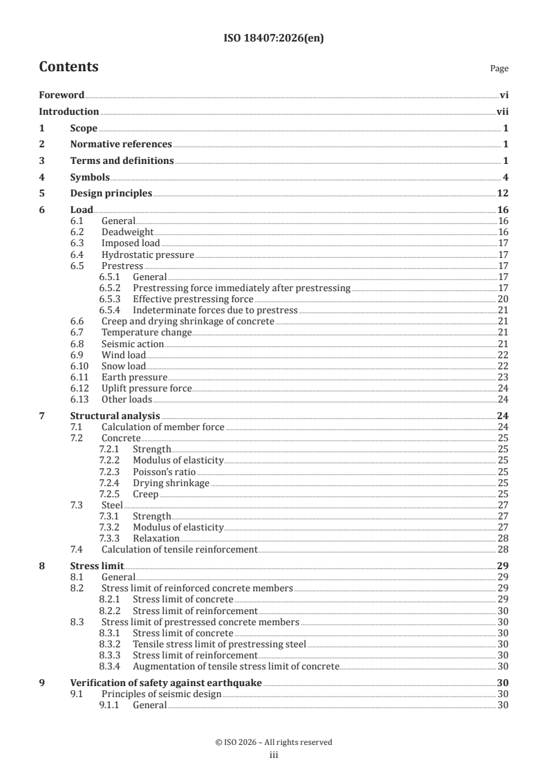
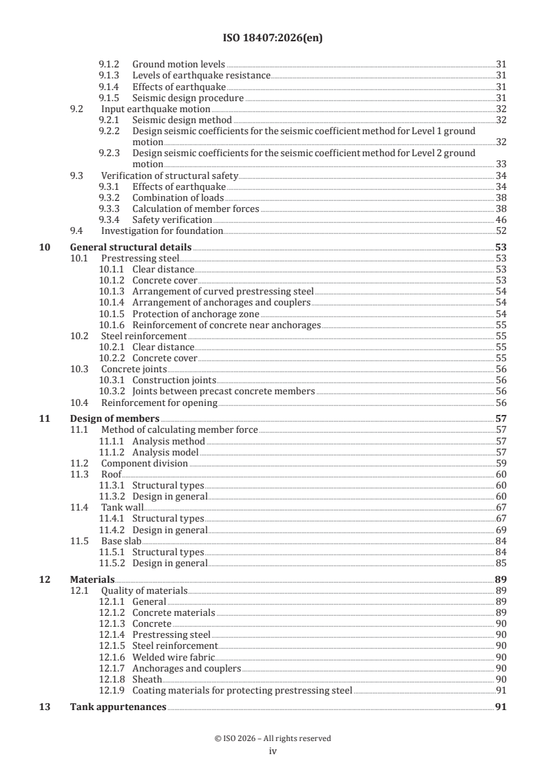
ISO 18407:2026 is an International Standard from ISO for the simplified design of prestressed concrete tanks for potable water. It gives planning, design and construction guidance for cylindrical ground-supported tanks, including load selection, structural analysis, stress limits, seismic verification and basic detailing, for designers, engineers and reviewers who need a self-contained design basis.
What does ISO 18407:2026 specify?
ISO 18407:2026 specifies guidelines for the planning, design and construction of a cylindrical prestressed concrete (PC) tank on the ground for potable water. It applies to tanks with a capacity of 30 000 m3 or less and a diameter-to-height ratio from 1,0 to 3,0.
ISO 18407:2026 also notes that when the ratio exceeds 3, the document is still used for design purposes except for the Hausner method. For tanks outside its scope, such as reinforced concrete tanks, underground tanks and elevated tanks, the document can still be used for common elements where that makes sense.
The document is organized into clauses on scope, normative references, terms and definitions, symbols, design principles, loads, structural analysis, stress limits, earthquake verification, general structural details, member design, materials and tank appurtenances. It ends with Annex A, which is an informative example of design calculation.
What are the key requirements of ISO 18407:2026?
ISO 18407:2026 is built around a simplified elastic design approach. Clause 5 says the tank site should be investigated carefully, and the design should check both ordinary service conditions and earthquake conditions. In practice, that means the designer must look at topography, geology and disaster history before fixing the structural concept.
Design basis and analysis method
Clause 5 requires the elastic method for member safety and serviceability. The document treats watertightness as a primary design objective, so cracking must be controlled and tensile reinforcement used where tensile stress appears. Clause 7 says member forces are calculated by elastic theory, with the concrete cross-section taken as effective even if partial cracking is expected.
This matters because the whole document is aimed at a simplified but conservative design route. The designer is expected to use the document as a whole, not pick only selected parts.
Loads to consider
Clause 6 groups loads into primary loads, subsidiary loads and particular loads. It covers deadweight, imposed load, hydrostatic pressure, prestress, creep and drying shrinkage, temperature change, seismic action, wind load, snow load, earth pressure and uplift pressure.
In practice, this means the load set is not just the water pressure. Site conditions, roof inspection loads, soil effects, groundwater, temperature difference and earthquake effects all need to be checked before finalizing member forces.
Seismic design and earthquake levels
Clause 6 and Clause 9 require earthquake design to consider Level 1 and Level 2 ground motions. The seismic design checks include ground motion input, dynamic water pressure, sloshing, soil-structure interaction and foundation stability.
For a reader, this means the tank is not designed only for static loading. The designer must verify both structural resistance and functional performance under earthquake action, including the ability to retain water serviceability after the event.
Stress limits and load combinations
Clause 8 sets stress limits for reinforced concrete members and prestressed concrete members. It also gives extra coefficients for selected load combinations, including temperature difference, wind load and Level 1 earthquake action.
In practice, this tells the designer how to judge whether a section remains acceptable under combined actions. It is also the clause that ties the ordinary-state checks back to serviceability and safety expectations.
Detailing of prestressing steel, joints and openings
Clause 10 covers clear distance, concrete cover, anchorages, couplers, protection of the anchorage zone, construction joints, joints between precast members and reinforcement around openings. These are the practical details that protect durability and watertightness.
For a project team, this clause is important because many tank problems start at discontinuities and penetrations. Openings should be controlled carefully, especially in the wall where stress is high.
Member design for roof, wall and base slab
Clause 11 divides the tank into roof, wall and base slab and gives design guidance for each. It also describes analysis models, including axisymmetric thin-wall shell analysis, finite elements and theoretical solutions.
This matters because the document treats the tank as an interacting system. Roof, wall and base slab are not designed in isolation, and support conditions at the wall bottom affect the member forces.
Material and appurtenance requirements
Clause 12 points to concrete, prestressing steel, reinforcement, welded wire fabric, anchorages, couplers, sheath and coating materials. Clause 13 covers ladders, stairs, handrails, manholes, ventilators, lightning rods, piping, catch basins, water-level gauges, rainwater treatment and protection equipment.
In practice, this makes the standard useful beyond pure structural design. It also helps a buyer or checker see which accessories and safety items are expected for a potable-water tank.
What terms does ISO 18407:2026 define?
- Bending analysis - A method for finding membrane force and bending moment while accounting for the boundary condition at the dome base.
- Clearance - The distance between the designed high-water level and the upper edge of the tank wall.
- Dynamic water pressure - Water pressure excited by earthquake motion.
- Housner method - A conventional approximate analysis method for liquid vibration.
- Prestressed concrete cylindrical tank - A tank with a roof, cylindrical wall and base slab, where prestressing steel is provided at least in the circumferential direction.
- Tank empty - The condition where no water is present in the tank.
- Tank full - The condition where the water level reaches the design high-water level.
- Waterstop - A plate inserted in joints between concrete lifts and wall-bottom joints to stop water.
Who uses ISO 18407:2026?
ISO 18407:2026 is used by structural engineers, concrete specialists, water utility designers, consultants, contractors and reviewing authorities involved in potable-water storage tanks. It is also relevant to quality managers and buyers who need to define tank design expectations for a project.
The document is especially aimed at less-developed areas, where a self-contained simplified design rule is useful. It supports planning, design, construction and checking of PC water tanks in earthquake-prone regions and in projects where potable-water watertightness is a key requirement.
What changed in ISO 18407:2026 from the previous edition?
ISO 18407:2026 cancels and replaces ISO 18407:2018. The foreword states that the main changes are:
- a design flow has been added;
- informative annexes providing particular local conditions have been deleted;
- terms and symbols have been corrected for consistency;
- errors have been corrected in some formulae.
Which standards are used with ISO 18407:2026?
ISO 18407:2026 cites the following normative references:
- ISO 1920-3 and ISO 1920-4 - concrete test specimen preparation, curing and hardened-concrete strength testing.
- ISO 3010 - seismic actions on structures.
- ISO 6934-1 to ISO 6934-5 - prestressing steel requirements for the main product forms.
- ISO 6935-1 to ISO 6935-3 - reinforcement steel and welded fabric.
- ISO 12439 - mixing water for concrete.
- ISO 14654 - epoxy-coated steel for concrete reinforcement.
- ISO 14824-3 - test methods for grout for prestressing tendons.
These references provide the material and test framework that ISO 18407:2026 builds on, especially for concrete, steel, grout and seismic action.
What does the ISO 18407:2026 document contain?
ISO 18407:2026 contains a clause structure that walks from design basis to detailing and appurtenances. Clause 4 lists symbols for geometry, loads, stiffness, material strengths and seismic terms, so the formulas can be used consistently across the document.
The body of the standard includes load models for deadweight, hydrostatic pressure, soil and uplift, as well as methods for temperature, wind, snow and earthquake actions. It also includes structural analysis methods for shell behavior, creep and drying shrinkage, prestress losses and tensile reinforcement.
For seismic design, the document provides procedures for dynamic water pressure, sloshing, member-force calculation and foundation checks, including spread and pile foundations. For ordinary design, it includes stress-limit checks, wall-bottom behavior, prestressing arrangement, opening reinforcement and the main detailing rules for roof, wall and base slab.
Annex A is an informative worked example of design calculation. It shows the design sequence for a tank, including roof, dome ring, wall, base slab, prestress losses, load combinations and earthquake verification, which helps readers apply the clauses in a real calculation flow.
Relations
- Effective Date
- 20-Jul-2024
Get Certified
Connect with accredited certification bodies for this standard

DIBt (Deutsches Institut für Bautechnik)
German Institute for Building Technology.
DIN CERTCO
DIN Group product certification.

Aboma Certification B.V.
Specialized in construction, metal, and transport sectors.
Sponsored listings
Frequently Asked Questions
ISO 18407:2026 is a standard published by the International Organization for Standardization (ISO). Its full title is "Simplified design of prestressed concrete tanks for potable water". This standard covers: This document provides guidelines for the planning, design and construction of a cylindrical tank constructed on the ground with prestressed concrete (PC) for use with potable water tank. This document is applicable to PC tanks for potable water with a capacity of 30 000 m3 or less and the diameter-to-height ratio (D/H) from 1,0 to 3,0. NOTE 1 The D/H ratio within the range of 1 to 3 is generally considered as a reasonable shape for a PC water tank. However, even if the ratio exceeds 3, this document is applied for design purposes except for applying the Hausner method. NOTE 2 When designing and constructing a tank not covered by this document (reinforced concrete tanks, underground tanks, elevated tanks, etc.), a designer can refer to this document for common elements where possible.
This document provides guidelines for the planning, design and construction of a cylindrical tank constructed on the ground with prestressed concrete (PC) for use with potable water tank. This document is applicable to PC tanks for potable water with a capacity of 30 000 m3 or less and the diameter-to-height ratio (D/H) from 1,0 to 3,0. NOTE 1 The D/H ratio within the range of 1 to 3 is generally considered as a reasonable shape for a PC water tank. However, even if the ratio exceeds 3, this document is applied for design purposes except for applying the Hausner method. NOTE 2 When designing and constructing a tank not covered by this document (reinforced concrete tanks, underground tanks, elevated tanks, etc.), a designer can refer to this document for common elements where possible.
ISO 18407:2026 is classified under the following ICS (International Classification for Standards) categories: 91.080.40 - Concrete structures. The ICS classification helps identify the subject area and facilitates finding related standards.
ISO 18407:2026 has the following relationships with other standards: It is inter standard links to ISO 18407:2018. Understanding these relationships helps ensure you are using the most current and applicable version of the standard.
ISO 18407:2026 is available in PDF format for immediate download after purchase. The document can be added to your cart and obtained through the secure checkout process. Digital delivery ensures instant access to the complete standard document.
Standards Content (Sample)
International
Standard
ISO 18407
Second edition
Simplified design of prestressed
2026-06
concrete tanks for potable water
Conception simplifiée du réservoir pour l'eau potable en béton
pré-armé
Reference number
© ISO 2026
All rights reserved. Unless otherwise specified, or required in the context of its implementation, no part of this publication may
be reproduced or utilized otherwise in any form or by any means, electronic or mechanical, including photocopying, or posting on
the internet or an intranet, without prior written permission. Permission can be requested from either ISO at the address below
or ISO’s member body in the country of the requester.
ISO copyright office
CP 401 • Ch. de Blandonnet 8
CH-1214 Vernier, Geneva
Phone: +41 22 749 01 11
Email: copyright@iso.org
Website: www.iso.org
Published in Switzerland
ii
Contents Page
Foreword .vi
Introduction .vii
1 Scope . 1
2 Normative references . 1
3 Terms and definitions . 1
4 Symbols . 4
5 Design principles .12
6 Load . .16
6.1 General .16
6.2 Deadweight .16
6.3 Imposed load .17
6.4 Hydrostatic pressure .17
6.5 Prestress .17
6.5.1 General .17
6.5.2 Prestressing force immediately after prestressing .17
6.5.3 Effective prestressing force . 20
6.5.4 Indeterminate forces due to prestress .21
6.6 Creep and drying shrinkage of concrete .21
6.7 Temperature change .21
6.8 Seismic action .21
6.9 Wind load. 22
6.10 Snow load. 22
6.11 Earth pressure . 23
6.12 Uplift pressure force . .24
6.13 Other loads .24
7 Structural analysis .24
7.1 Calculation of member force .24
7.2 Concrete . 25
7.2.1 Strength . 25
7.2.2 Modulus of elasticity . 25
7.2.3 Poisson’s ratio . 25
7.2.4 Drying shrinkage . 25
7.2.5 Creep . 25
7.3 Steel .27
7.3.1 Strength .27
7.3.2 Modulus of elasticity .27
7.3.3 Relaxation . 28
7.4 Calculation of tensile reinforcement . 28
8 Stress limit . .29
8.1 General . 29
8.2 Stress limit of reinforced concrete members . 29
8.2.1 Stress limit of concrete . 29
8.2.2 Stress limit of reinforcement . 30
8.3 Stress limit of prestressed concrete members . 30
8.3.1 Stress limit of concrete . 30
8.3.2 Tensile stress limit of prestressing steel . 30
8.3.3 Stress limit of reinforcement . 30
8.3.4 Augmentation of tensile stress limit of concrete . 30
9 Verification of safety against earthquake .30
9.1 Principles of seismic design . 30
9.1.1 General . 30
iii
9.1.2 Ground motion levels .31
9.1.3 Levels of earthquake resistance .31
9.1.4 Effects of earthquake .31
9.1.5 Seismic design procedure .31
9.2 Input earthquake motion .32
9.2.1 Seismic design method .32
9.2.2 Design seismic coefficients for the seismic coefficient method for Level 1 ground
motion .32
9.2.3 Design seismic coefficients for the seismic coefficient method for Level 2 ground
motion . 33
9.3 Verification of structural safety . 34
9.3.1 Effects of earthquake . 34
9.3.2 Combination of loads . 38
9.3.3 Calculation of member forces . 38
9.3.4 Safety verification . 46
9.4 Investigation for foundation .52
10 General structural details .53
10.1 Prestressing steel. 53
10.1.1 Clear distance . 53
10.1.2 Concrete cover . 53
10.1.3 Arrangement of curved prestressing steel . 54
10.1.4 Arrangement of anchorages and couplers . 54
10.1.5 Protection of anchorage zone . 54
10.1.6 Reinforcement of concrete near anchorages . 55
10.2 Steel reinforcement . 55
10.2.1 Clear distance . 55
10.2.2 Concrete cover . 55
10.3 Concrete joints . 56
10.3.1 Construction joints . 56
10.3.2 Joints between precast concrete members . 56
10.4 Reinforcement for opening . 56
11 Design of members .57
11.1 Method of calculating member force .57
11.1.1 Analysis method .57
11.1.2 Analysis model .57
11.2 Component division .59
11.3 Roof . 60
11.3.1 Structural types . 60
11.3.2 Design in general . 60
11.4 Tank wall .67
11.4.1 Structural types .67
11.4.2 Design in general . 69
11.5 Base slab . 84
11.5.1 Structural types . 84
11.5.2 Design in general . 85
12 Materials .89
12.1 Quality of materials . 89
12.1.1 General . 89
12.1.2 Concrete materials . 89
12.1.3 Concrete . 90
12.1.4 Prestressing steel . 90
12.1.5 Steel reinforcement . 90
12.1.6 Welded wire fabric. 90
12.1.7 Anchorages and couplers . 90
12.1.8 Sheath . 90
12.1.9 Coating materials for protecting prestressing steel .91
13 Tank appurtenances .91
iv
13.1 Ladders, stairs and handrails .91
13.2 Manhole and water sampling outlet .91
13.3 Ventilators . 92
13.4 Lightning rods . 92
13.5 Piping . 92
13.6 Catch basin . 93
13.7 Water-level gauge . 93
13.8 Rainwater treatment. 93
13.9 Protection equipment . 93
Annex A (informative) Example of design calculation .94
Bibliography .152
v
Foreword
ISO (the International Organization for Standardization) is a worldwide federation of national standards
bodies (ISO member bodies). The work of preparing International Standards is normally carried out through
ISO technical committees. Each member body interested in a subject for which a technical committee
has been established has the right to be represented on that committee. International organizations,
governmental and non-governmental, in liaison with ISO, also take part in the work. ISO collaborates closely
with the International Electrotechnical Commission (IEC) on all matters of electrotechnical standardization.
The procedures used to develop this document and those intended for its further maintenance are described
in the ISO/IEC Directives, Part 1. In particular, the different approval criteria needed for the different types
of ISO document should be noted. This document was drafted in accordance with the editorial rules of the
ISO/IEC Directives, Part 2 (see www.iso.org/directives).
ISO draws attention to the possibility that the implementation of this document may involve the use of (a)
patent(s). ISO takes no position concerning the evidence, validity or applicability of any claimed patent
rights in respect thereof. As of the date of publication of this document, ISO had not received notice of (a)
patent(s) which may be required to implement this document. However, implementers are cautioned that
this may not represent the latest information, which may be obtained from the patent database available at
www.iso.org/patents. ISO shall not be held responsible for identifying any or all such patent rights.
Any trade name used in this document is information given for the convenience of users and does not
constitute an endorsement.
For an explanation of the voluntary nature of standards, the meaning of ISO specific terms and expressions
related to conformity assessment, as well as information about ISO's adherence to the World Trade
Organization (WTO) principles in the Technical Barriers to Trade (TBT), see www.iso.org/iso/foreword.html.
This document was prepared by Technical Committee ISO/TC 71, Concrete, reinforced concrete and
prestressed concrete, Subcommittee SC 5, Simplified design standard for concrete structures.
This second edition cancels and replaces the first edition (ISO 18407:2018), which has been technically
revised.
The main changes are as follows:
— design flow has been added;
— informative annexes providing particular local conditions have been deleted;
— terms and symbols have been corrected to keep consistency;
— errors have been corrected in some formulae.
Any feedback or questions on this document should be directed to the user’s national standards body. A
complete listing of these bodies can be found at www.iso.org/members.html.
vi
Introduction
The aim of this document is to provide rules for the design and construction of prestressed concrete water
tanks to be built in less-developed areas of the world. The design rules are based on simplified worldwide-
accepted strength models. This document is self-contained; therefore actions (loads) and simplified analysis
procedures are included, as well as minimum acceptable construction practice guidelines.
A great effort was made to include self-explanatory tables, graphics and design aids to simplify the use of
this document and provide procedures. Notwithstanding, the economic implications of the conservatism
inherent in approximate procedures as a substitution to sound and experienced engineering should be a
matter of concern to the designer who employs this document and to the owner who hires him.
A prestressed concrete tank for potable water generally comprises the roof, wall and base slab. The roof
is made to entirely cover the top of the cylindrical wall to protect the water from contamination with
rainwater, etc. In many cases, it is made in the form of a dome shaped like a convex circular plate cut off
from a sphere. The wall is a vertical cylinder that forms a container for water in combination with the flat
base slab. Only the wall of a prestressed concrete water tank is made with prestressed concrete, while
the roof and base slab are made with reinforced concrete. Prestress is generally applied to the wall using
prestressing steel in the vertical and circumferential directions, but in some cases, prestress is applied only
to the circumferential direction. For this reason, this document defines a prestressed concrete cylindrical
tank as a structure having prestressing steel at least in the circumferential direction of the wall to apply
prestress, to cover both types. Therefore, the roof, base slab and wall in the vertical direction may not
necessarily be of prestressed concrete construction but may be of reinforced concrete construction.
A prestressed concrete water tank construction is generally adopted to preserve a water storage facility
with the aim of preventing severe secondary disasters and allowing the standing water to be used as an
emergency water supply. For this reason, it is required to be designed as a rule as a high degree of importance.
The minimum dimensional provisions contained in this document are intended to account for undesirable
side effects that will require more sophisticated analysis and design procedures. Material and construction
provisions are aimed at site-mixed concrete, as well as ready-mixed concrete and steel of the minimum
available strength grades.
The earthquake-resistance provisions are included to account for the fact that numerous developing regions
of the world occur in earthquake-prone areas. The earthquake resistance is based upon the employment of
structural concrete walls (shear walls) that limit the lateral deformations of the structure and provide for
its lateral strength.
This document contains provisions that can be modified by a national standards body due to local design
and construction requirements and practices. The national standards body is expected to review the values
(numerical values related to physical properties, limits, coefficients, and various construction procedures
for each material) and may substitute alternative definitive values for these elements for use in the national
application of this document.
vii
International Standard ISO 18407:2026(en)
Simplified design of prestressed concrete tanks for potable
water
1 Scope
This document provides guidelines for the planning, design and construction of a cylindrical tank
constructed on the ground with prestressed concrete (PC) for use with potable water tank.
This document is applicable to PC tanks for potable water with a capacity of 30 000 m or less and the
diameter-to-height ratio (D/H) from 1,0 to 3,0.
NOTE 1 The D/H ratio within the range of 1 to 3 is generally considered as a reasonable shape for a PC water tank.
However, even if the ratio exceeds 3, this document is applied for design purposes except for applying the Hausner
method.
NOTE 2 When designing and constructing a tank not covered by this document (reinforced concrete tanks,
underground tanks, elevated tanks, etc.), a designer can refer to this document for common elements where possible.
2 Normative references
The following documents are referred to in the text in such a way that some or all of their content constitutes
requirements of this document. For dated references, only the edition cited applies. For undated references,
the latest edition of the referenced document (including any amendments) applies.
ISO 1920-3, Testing of concrete — Part 3: Making and curing test specimens
ISO 1920-4, Testing of concrete — Part 4: Strength of hardened concrete
ISO 3010, Bases for design of structures — Seismic actions on structures
ISO 6934-1, Steel for the prestressing of concrete — Part 1: General requirements
ISO 6934-2, Steel for the prestressing of concrete — Part 2: Cold-drawn wire
ISO 6934-3, Steel for the prestressing of concrete — Part 3: Quenched and tempered wire
ISO 6934-4, Steel for the prestressing of concrete — Part 4: Strand
ISO 6934-5, Steel for the prestressing of concrete — Part 5: Hot-rolled steel bars with or without subsequent
processing
ISO 6935-1, Steel for the reinforcement of concrete — Part 1: Plain bars
ISO 6935-2, Steel for the reinforcement of concrete — Part 2: Ribbed bars
ISO 6935-3, Steel for the reinforcement of concrete — Part 3: Welded fabric
ISO 12439, Mixing water for concrete
ISO 14654, Epoxy-coated steel for the reinforcement of concrete
ISO 14824-3, Grout for prestressing tendons — Part 3: Test methods
3 Terms and definitions
For the purposes of this document, the following terms and definitions apply.
ISO and IEC maintain terminology databases for use in standardization at the following addresses:
— ISO Online browsing platform: available at https:// www .iso .org/ obp
— IEC Electropedia: available at https:// www .electropedia .org/
3.1
bending analysis
method for determining the membrane force and bending moment in consideration of the boundary
conditions at the base of the dome
3.2
clearance
distance between the designed high-water level and the upper edge of the tank wall
3.3
convective pressure
pressure produced by oscillation of the water as the consequences of impulsive pressure (3.16)
3.4
cylindrical prestressed concrete tank
concrete tank comprising the roof, cylindrical wall and base slab, for which prestressing steel is provided at
least in the circumferential direction to apply prestress
3.5
dome ring
circular beam provided along the base of the roof of a spherical or other shape of the dome to control radial
displacement at the base of the roof
3.6
dynamic water pressure
water pressure excited by earthquake motion
3.7
embedded system
system of applying prestress, whereby circumferential prestressing steel is provided within concrete
members
3.8
fixed support
wall-bottom connection, whereby the rotation or horizontal displacement of the wall with respect to the
bottom is not allowed
3.9
foundation slab
reinforced concrete or prestressed concrete slab provided in contact with the bottom surface of the base
slab
3.10
freely sliding support
wall-bottom connection, whereby the rotation and horizontal displacement of the wall with respect to the
bottom are allowed
3.11
hinged support
wall-bottom connection, whereby the rotation of the wall with respect to the bottom is allowed
3.12
hoop tension
circumferential axial tensile force generated by such loads as water pressure
3.13
horizontal thrust
horizontal component of the axial force in the meridian direction of the dome at the base of the dome
3.14
Housner method
conventional approximate analysis method for liquid vibration proposed by G. W. Housner
3.15
imposed load
load of portions not directly included in the design calculation as structural members and load applied to
the roof for such purposes as inspection
3.16
impulsive pressure
pressure associated with inertia force (3.17) produced by impulsive movements of the tank wall
3.17
inertia force
force given by the product of the mass of the structure and the structural response acceleration due to
ground motion by earthquake
3.18
in-plane shear force
shear force that acts parallel to the shell surface
3.19
membrane floor
part other than the ring plate of the base slab that does not resist bending moments
3.20
membrane force
in-plane axial force of a shell structure
3.21
out-of-plane shear force
shear force that acts at a right angle to the shell surface
3.22
particular load
special load that acts depending on the natural conditions of the tank construction site
Note 1 to entry: Particular load is judged as a primary load (3.24) or a subsidiary load (3.29) on a case-by-case basis.
3.23
pilaster
rectangular projections from the tank wall along its generatrix lines for anchoring circumferential
prestressing steel
3.24
primary load
load that constantly acts
3.25
ring plate
peripheral part of the base slab for transmitting forces primarily from the tank wall to the ground
3.26
sloshing
vibration of a solid oscillating surface generated in response to relatively long-period components of an
earthquake
3.27
spherical dome
curved shell in the form of a part of a sphere cut off by a plane
3.28
subsidiary load
load other than those considered as primary load
3.29
tank empty
state in which no water is present in the tank
3.30
tank full
state in which the water level in the tank reaches the design high water level
3.31
velocity potential method
method for a theoretical solution to irrotational vibration of a non-compressive and non-viscous fluid
3.32
waterstop
plate inserted in joints between concrete lifts and the wall-bottom joints for waterstopping
4 Symbols
A projection area
A area subjected to the effect of anchorage set
ep
A area of concrete subjected to bearing load
b
A cross-sectional area of member
c
A cross-sectional area of concrete
c
A total area of concrete surface
c
A surface area of dome
d
A cross-sectional area of element i
i
A cross-sectional area of prestressing steel
p
A cross-sectional area of tensile reinforcement
s
b member width
C wind force coefficient
C earth pressure coefficient
e
C structure characteristic coefficient
s
C correction factor by region
z
c concrete cover depth
D inner diameter of tank
D correction factor dependent on damping constant
he
D flexural stiffness of node i
i
D response reduction ratio due to plastic deformability
η
E elastic modulus
E elastic modulus of concrete
c
E elastic modulus of prestressing steel
p
E elastic modulus of steel reinforcement
s
F prestressing force applied to dome ring
d
f’ design compressive strength of concrete
cd
f’ characteristic compressive strength of concrete
ck
f tensile strength of prestressing steel
pu
f yield strength of prestressing steel
py
f yield strength of steel reinforcement
sy
f tensile strength of concrete
t
f design tensile strength of prestressing steel
ud
f design yield strength of steel reinforcement and structural steel
yd
g gravitational acceleration
g uniform pressure
H height of tank
H design depth of water from the base
H distance from the lower edge of tank wall to the point of action of the dome inertia force or
G
other partial weight inertia force
H length of thickened zone of tank wall (haunch height)
h
H total height of earth pressure action
s
H horizontal thrust
t
h height from the ground surface
h rise of dome
d
h height above the base of the wall to the centre of gravity of the impulsive lateral force excluding
rE
base pressure
h height above the base of the wall to the centre of gravity of the impulsive lateral force including
rI
base pressure
h height above the base of the wall to the centre of gravity of the convective lateral force excluding
sE
base pressure
h height above the base of the wall to the centre of gravity of the convective lateral force including
sI
base pressure
h virtual thickness of member
th
I second moment of area of element i
i
J vessel function
K flexural stiffness
K design horizontal seismic coefficient
h
K standard horizontal seismic coefficient for Level 1 ground motion
h01
K standard horizontal seismic coefficient for Level 2 ground motion
h02
K design horizontal seismic coefficient for Level 1 ground motion
h1
K design horizontal seismic coefficient for Level 2 ground motion
h2
K horizontal subgrade reaction modulus
s
K vertical subgrade reaction modulus
v
K vertical spring constants of node i
vi
K design vertical seismic coefficient for Level 1 ground motion
v1
K design vertical seismic coefficient for Level 2 ground motion
v2
K rotational spring constants of node i
θi
k spring constant of bearing
k coefficient considering the characteristics of foundations
α
k coefficient considering the rigidity of base slab
β
L ring plate length
rp
L water depth
w
l length from the tension end of prestressing steel to the design cross-section
l basic development length
d
l maximum spacing of prestressing steel
max
l length of prestressing steel
p
l distance from the upper edge of tank wall to the starting point of the action of distributed load
l distance from the upper edge of tank wall to the end point of the action of distributed load
M corrected vertical bending moment
a
M vertical bending moment of member
d
M vertical bending moment at the bottom of tank wall generated by changes in the curvature
e
radius of tank wall
M bending moment per unit length in the radial directions at node i
ri
M design flexural fracture capacity
ud
M vertical bending moment
x
M bending moment at node i determined by planar frame analysis
xi
M torsional moment
xϕ
M vertical bending moment
x0
M restraining moment at the bottom of tank wall
M vertical bending moment at the bottom of tank wall with a constant thickness
0c
M vertical bending moment at the bottom of tank wall generated by curvature changes when wall
0e
thickness is constant at t
M vertical bending moment at the bottom of tank wall
0f
M vertical bending moment at the bottom of tank wall considering an increase in wall bottom
0h
thickness
M (x) moment at distance, x from the lower edge of tank wall
0T
M vertical bending moment at the bottom of tank wall generated by the effect of Poisson’s ratio
0ν
due to vertical prestress when wall thickness is constant
vertical bending moment obtained from axisymmetric analysis under equivalent load
M
x
M circumferential bending moment
ϕ
M torsional moment
ϕx
M bending moment per unit length in the circumferential directions at node i
θi
M vertical bending moment at ξ from the top of the wall
ξ
N axial force in the vertical direction
x
N (x) vertical axial force at distance, x from the lower edge of tank wall
xo
N in-plane shear force
xϕ
N membrane force in the meridian direction
ϕ
N membrane force per unit length of dome in the meridian direction
ϕd
N in-plane shear force
ϕx
N circumferential axial force due to non-axisymmetric loads
ϕ0
N membrane force in the parallel direction
θ
N membrane force per unit length of dome in the parallel direction
θd
n elastic modulus ratio (=E /E )
p c
P prestressing force in the vertical direction
P concentrated load acting on node i
Fi
P (r) maximum impulsive pressure acting on base slab
br
P (r) maximum convective pressure acting on base slab
bs
P tensile force of prestressing steel at the jack position
i
P dynamic water pressure at the lower edge
l
P horizontal impulsive force acting on the centre of gravity
r
P horizontal convective force acting on the centre of gravity
s
P total earth pressure
sh
P concentrated load per unit length acting on node i
si
P tensile force o
...