

ISO 19457:2026
(Main)Rolling bearings — Roller blocks as subassemblies for linear motion rolling bearings — Boundary dimensions and tolerance values
- Abstract
This document specifies the boundary dimensions and tolerances for Types A to D of roller blocks. Types E and F of roller blocks are given in Annex A. They require fixing parts and are not yet produced on a broad manufacturer base.
- Status
- Published
- Publication Date
- 01-Jul-2026
- Technical Committee
- ISO/TC 4/SC 11 - Linear motion rolling bearings
- Drafting Committee
- ISO/TC 4/SC 11 - Linear motion rolling bearings
- Current Stage
- 6060 - International Standard published
- Start Date
- 02-Jul-2026
- Due Date
- 18-Jan-2026
- Completion Date
- 02-Jul-2026

ISO 19457:2026 is an ISO International Standard for roller blocks as subassemblies for linear motion rolling bearings. It specifies the boundary dimensions and tolerance values used to design, check, and specify roller blocks, mainly for manufacturers, machine builders, inspectors, and buyers who need a common dimensional basis.
What does ISO 19457:2026 specify?
ISO 19457:2026 specifies the boundary dimensions and tolerances for roller block Types A to D. Annex A gives Types E and F, which use fixing parts and are described as not yet produced on a broad manufacturer base.
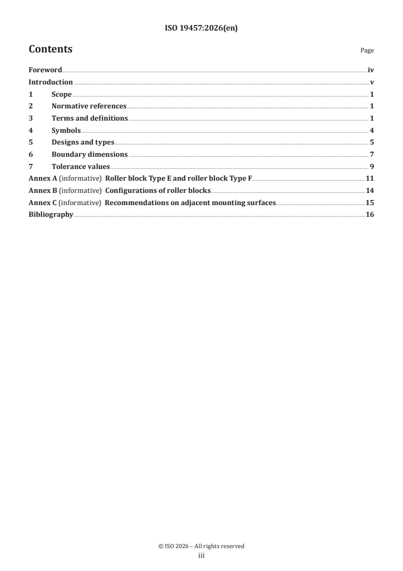
The document is organized into seven clauses plus three informative annexes:
| Annex | What it covers |
|---|---|
| Annex A | Roller block Type E and roller block Type F |
| Annex B | Configurations of roller blocks |
| Annex C | Recommendations on adjacent mounting surfaces |
Clauses 1 to 3 set the scope, required references, and terms. Clauses 4 to 7 then define symbols, show the different designs and types, give the boundary dimensions, and state the tolerance values. In practice, that structure lets a reader move from terminology to geometry and then to allowable variation without searching through unrelated material.
What are the key requirements of ISO 19457:2026?
ISO 19457:2026 gives the dimensional basis for roller blocks first, then adds the tolerance system that controls how precisely they are made. For users, this means the standard is mainly about interchangeability, fit, and inspection of roller block subassemblies.
Types and design scope
Clause 1 limits the main specification to roller block Types A to D. Annex A extends the document with Types E and F, which require mounting plates and, depending on the type, a mounting groove.
In practice, this tells a designer which roller block families are standardized in the main body of the document and which ones are treated as additional, informative examples. It matters when selecting a part for a machine redesign or a spare-parts strategy.
References and terminology
Clause 2 makes ISO 15241 and ISO 24393:2008 part of the document’s requirements. Clause 3 then uses the vocabulary from ISO 24393:2008 and adds terms specific to this document.
This matters because the dimensional tables and figures only make sense if the reader uses the same terms for roller block body, roller holding part, mounting surface, and rolling surface. That reduces misinterpretation when drawing, ordering, or inspecting parts.
Symbols and nominal dimensions
Clause 4 defines the symbols used for widths, lengths, heights, bolt-hole spacing, thread designations, and tolerance-related deviations. It also states that the symbols shown in the figures and tables denote nominal dimensions unless otherwise specified.
In practice, this is the key to reading the tables correctly. A buyer or inspector can use the same symbols in drawings, requests for quotation, and incoming inspection records.
Designs and configurations
Clause 5 shows the main roller block design families in figures and notes that the internal design is left to the manufacturer’s discretion. It also points to Annex B for the different configurations.
That means the standard fixes the external functional geometry, while leaving internal construction details open where they do not affect the boundary dimensions. For users, this supports sourcing from different manufacturers without locking the design to one internal layout.
Boundary dimensions
Clause 6 gives the boundary dimensions in Tables 2 to 6 for Types A, B, C1, C2, and D. The tables cover size designations, overall width and length, height, bolt-hole spacing, screw-thread designation where applicable, and related dimensions.
This is the section used when checking whether a roller block will fit the adjacent construction and whether different products can be treated as the same size family. It also shows the distinction between the metric and inch series for Type C.
Tolerance classes
Clause 7 defines four precision grades: G, E, D, and C, with subclasses listed in the tolerance table. The table gives limits for the main dimensional variations and deviations in micrometres.
In practice, this is the manufacturing and inspection control point. It tells a supplier which precision level to produce and tells a purchaser what level of dimensional scatter to expect.
Adjacent mounting surfaces
Clause 7 points to Annex C for recommendations on adjacent mounting surfaces and adjacent parts. Annex C adds guidance on tolerancing the surrounding structure.
That matters because a roller block can meet its own dimensions and still perform poorly if the mounting surfaces are not compatible. The annex helps designers control the parts that the roller block is mounted against.
What terms does ISO 19457:2026 define?
- Roller block - A linear bearing subassembly made of a roller block body and closed loops of recirculating rollers, designed for unlimited motion along a flat rail or flat guideway.
- Roller block body - The cuboid load-supporting part of the roller block, with one or more raceways on an outside surface.
- Roller holding part - The parts of the roller block other than the rollers and body that retain and guide the rollers in a recirculation path.
- Mounting surface - The surface of the roller block that is fixed to the adjacent construction.
- Rolling surface - The plane that is theoretically tangential to the cylindrical surfaces of the rollers.
- Type C1 - The metric series designation for Type C roller blocks.
- Type C2 - The inch series designation for Type C roller blocks.
Who uses ISO 19457:2026?
ISO 19457:2026 is used by manufacturers of rolling bearings and linear motion components, especially those making roller blocks for linear motion systems. It is also used by machine designers and equipment builders who need the external size and mounting geometry to match a rail, guideway, or adjacent structure.
Quality managers and inspection teams use it to verify dimensions, tolerance class, and mounting-related geometry. Buyers and maintenance teams use it when specifying or replacing roller block spare parts, especially in older linear motion applications where compatible parts are still needed.
Which standards are used with ISO 19457:2026?
- ISO 15241 - Provides the symbols for physical quantities used in the document.
- ISO 24393:2008 - Supplies the vocabulary for rolling bearings and the linear motion rolling bearing classification referenced in the title.
- ISO 12090-1 - Describes profiled rail guides for linear motion rolling bearings, and the introduction notes that these designs can replace the roller block design in this document.
- ISO 12090-2 - Gives the second part of the profiled rail guide family with the same replacement role noted in the introduction.
- ISO 273 - Gives clearance holes for bolts and screws, useful when adjacent mounting parts are being designed.
- ISO 286-1 and ISO 286-2 - Provide the ISO code system for linear-size tolerances, deviations, and fits, which supports the tolerance language used around adjacent parts.
What does the ISO 19457:2026 document contain?
ISO 19457:2026 contains an exploded-view example of a roller block, figures showing the mounting surfaces and rolling surface, and figures of the main designs and types. It also contains dimensional tables for the standardized sizes of Types A to D and separate tables for the informative Type E and Type F variants.
The tolerance section gives the precision classes and their allowed deviations. Annex B presents configurations and how roller location and mounting-hole arrangements differ between types. Annex C provides guidance figures for adjacent mounting surfaces and an example of how adjacent parts may be toleranced, which is useful when the roller block is part of a larger assembly.
Frequently Asked Questions
ISO 19457:2026 is a standard published by the International Organization for Standardization (ISO). Its full title is "Rolling bearings — Roller blocks as subassemblies for linear motion rolling bearings — Boundary dimensions and tolerance values". This standard covers: This document specifies the boundary dimensions and tolerances for Types A to D of roller blocks. Types E and F of roller blocks are given in Annex A. They require fixing parts and are not yet produced on a broad manufacturer base.
This document specifies the boundary dimensions and tolerances for Types A to D of roller blocks. Types E and F of roller blocks are given in Annex A. They require fixing parts and are not yet produced on a broad manufacturer base.
ISO 19457:2026 is classified under the following ICS (International Classification for Standards) categories: 21.100.20 - Rolling bearings. The ICS classification helps identify the subject area and facilitates finding related standards.
ISO 19457:2026 is available in PDF format for immediate download after purchase. The document can be added to your cart and obtained through the secure checkout process. Digital delivery ensures instant access to the complete standard document.
Standards Content (Sample)
International
Standard
ISO 19457
First edition
Rolling bearings — Roller blocks
2026-07
as subassemblies for linear motion
rolling bearings — Boundary
dimensions and tolerance values
Roulements — Roulements pour mouvement linéaire, sous-
ensembles, patin à rouleaux — Dimensions d'encombrement et
valeurs de tolérance
Reference number
© ISO 2026
All rights reserved. Unless otherwise specified, or required in the context of its implementation, no part of this publication may
be reproduced or utilized otherwise in any form or by any means, electronic or mechanical, including photocopying, or posting on
the internet or an intranet, without prior written permission. Permission can be requested from either ISO at the address below
or ISO’s member body in the country of the requester.
ISO copyright office
CP 401 • Ch. de Blandonnet 8
CH-1214 Vernier, Geneva
Phone: +41 22 749 01 11
Email: copyright@iso.org
Website: www.iso.org
Published in Switzerland
ii
Contents Page
Foreword .iv
Introduction .v
1 Scope . 1
2 Normative references . 1
3 Terms and definitions . 1
4 Symbols . 4
5 Designs and types . 5
6 Boundary dimensions . 7
7 Tolerance values . 9
Annex A (informative) Roller block Type E and roller block Type F .11
Annex B (informative) Configurations of roller blocks . 14
Annex C (informative) Recommendations on adjacent mounting surfaces .15
Bibliography .16
iii
Foreword
ISO (the International Organization for Standardization) is a worldwide federation of national standards
bodies (ISO member bodies). The work of preparing International Standards is normally carried out through
ISO technical committees. Each member body interested in a subject for which a technical committee
has been established has the right to be represented on that committee. International organizations,
governmental and non-governmental, in liaison with ISO, also take part in the work. ISO collaborates closely
with the International Electrotechnical Commission (IEC) on all matters of electrotechnical standardization.
The procedures used to develop this document and those intended for its further maintenance are described
in the ISO/IEC Directives, Part 1. In particular, the different approval criteria needed for the different types
of ISO document should be noted. This document was drafted in accordance with the editorial rules of the
ISO/IEC Directives, Part 2 (see www.iso.org/directives).
ISO draws attention to the possibility that the implementation of this document may involve the use of (a)
patent(s). ISO takes no position concerning the evidence, validity or applicability of any claimed patent
rights in respect thereof. As of the date of publication of this document, ISO had not received notice of (a)
patent(s) which may be required to implement this document. However, implementers are cautioned that
this may not represent the latest information, which may be obtained from the patent database available at
www.iso.org/patents. ISO shall not be held responsible for identifying any or all such patent rights.
Any trade name used in this document is information given for the convenience of users and does not
constitute an endorsement.
For an explanation of the voluntary nature of standards, the meaning of ISO specific terms and expressions
related to conformity assessment, as well as information about ISO's adherence to the World Trade
Organization (WTO) principles in the Technical Barriers to Trade (TBT), see www.iso.org/iso/foreword.html.
This document was prepared by Technical Committee ISO/TC 4, Rolling bearings, Subcommittee SC 11,
Linear motion rolling bearings.
Any feedback or questions on this document should be directed to the user’s national standards body. A
complete listing of these bodies can be found at www.iso.org/members.html.
iv
Introduction
Linear motion rolling bearing subassemblies as standardized in this document are a product that has been
on the market for several decades. It is projected that these products will become less important in future
technology. However, in some application areas there is still a need for spare parts.
The designs with profiled rail guides and linear motion rolling bearings in ISO 12090-1 and ISO 12090-2 can
replace the roller block design given in this document.
The title of this document applies the classification of linear motion rolling bearings as defined in
ISO 24393:2008, Annex A.
v
International Standard ISO 19457:2026(en)
Rolling bearings — Roller blocks as subassemblies for
linear motion rolling bearings — Boundary dimensions and
tolerance values
1 Scope
This document specifies the boundary dimensions and tolerances for Types A to D of roller blocks.
Types E and F of roller blocks are given in Annex A. They require fixing parts and are not yet produced on a
broad manufacturer base.
2 Normative references
The following documents are referred to in the text in such a way that some or all of their content constitutes
requirements of this document. For dated references, only the edition cited applies. For undated references,
the latest edition of the referenced document (including any amendments) applies.
ISO 15241, Rolling bearings — Symbols for physical quantities
ISO 24393:2008, Rolling bearings — Linear motion rolling bearings — Vocabulary
3 Terms and definitions
For the purposes of this document, the terms and definitions given in ISO 24393:2008 and the following
apply.
ISO and IEC maintain terminology databases for use in standardization at the following addresses:
— ISO Online browsing platform: available at https:// www .iso .org/ obp
— IEC Electropedia: available at https:// www .electropedia .org/
3.1
roller block
linear roller bearing
linear bearing subassembly consisting of roller block body and a number of closed loops of recirculating
rollers, which are designed to achieve unlimited motion along a flat rail or flat guideway
Note 1 to entry: An example of a roller block is illustrated in Figure 1.
[SOURCE: ISO 24393:2008, 03.01.07]
Key
1 roller block body (3.2)
2 rollers
3 roller holding part (3.3)
Figure 1 — Example of a roller block with exploded view
3.2
roller block body
cuboid part having rectangular cross-section of a roller block with one or more raceways on one of its
outside surfaces and supporting load
Note 1 to entry: See Figure 1.
[SOURCE: ISO 24393:2008, 04.01.07 modified – The wordings “having rectangular cross-section” as well as
“and supporting load” have been added. "basically" has been removed.]
3.3
roller holding part
parts of roller block except rollers and roller block body which together retain and guide the rollers in a
recirculation path
Note 1 to entry: See Figure 1.
3.4
mounting surface
surface of the roller block which is fixed to the adjacent construction
Note 1 to entry: See Figure 2.
a) Roller block Type A
b) Roller block Type B
c) Roller block Type C
d) Roller block Type D
e) Roller block Type E
f) Roller block Type F
Key
1 mounting surface
Figure 2 — Mounting surfaces of roller blocks
3.5
rolling surface
plane theoretically tangential to the cylindrical surfaces of rollers
Note 1 to entry: See Figure 3.
Key
1 rolling surface
Figure 3 — Rolling surface
4 Symbols
For the purposes of this document, the symbols given in ISO 15241 and the following apply, see Table 1.
The symbols (except those for tolerances) shown in Figures 4 to 7 and the values given in Tables 2 to 6
denote nominal dimensions, unless specified otherwise.
Table 1 — Symbols
Symbol Description Unit
B Overall width of roller block mm
B Width of roller holding part mm
H Height from mounting surface to rolling surface mm
H Height of roller block mm
h Overall length of bolt hole mm
h Height of mounting flange mm
J Centre distance between mounting bolt holes (width) mm
J Centre distance between mounting bolt holes (length) mm
L Length of roller block mm
L Length of mounting flange mm
L Length of mounting surface mm
M Designation of internal screw thread for mounting bolts -
N Diameter of mounting bolt holes mm
a, b
V Variation of the sorting height µm
HmL
V Variation of height from mounting surface to rolling surface µm
Hs
∆
Deviation of overall width of roller block µm
Bs
∆ Deviation of width of roller holding p
...