

kSIST prES 200 674-1 V2.3.1:2012
(Main)Intelligent Transport Systems (ITS) - Road Transport and Traffic Telematics (RTTT); Dedicated Short Range Communications (DSRC) - Part 1: Technical characteristics and test methods for High Data Rate (HDR) data transmission equipment operating in the 5,8 GHz Industrial, Scientific and Medical (ISM) band
- Abstract
Correct minor editorial and technical inconsistencies found in the standard after STF 422 test specifications.
- Status
- Not Published
- Technical Committee
- MOC - Mobile Communications
- Current Stage
- 5020 - Formal vote (FV) (Adopted Project)
- Start Date
- 18-Jul-2012
- Due Date
- 05-Sep-2012
- Completion Date
- 07-Sep-2012
Buy Documents
es_20067401v020301m - Intelligent Transport Systems (ITS); Road Transport and Traffic Telematics (RTTT); Dedicated Short Range Communications (DSRC); Part 1: Technical characteristics and test methods for High Data Rate (HDR) data transmission equipment operating in the 5,8 GHz Industrial, Scientific and Medical (ISM) band
es_20067401v020301p - Intelligent Transport Systems (ITS); Road Transport and Traffic Telematics (RTTT); Dedicated Short Range Communications (DSRC); Part 1: Technical characteristics and test methods for High Data Rate (HDR) data transmission equipment operating in the 5,8 GHz Industrial, Scientific and Medical (ISM) band
kSIST prES 200 674-1 V2.3.1:2012 is a SIST standard based on ETSI ES 200 674-1 V2.3.1. It specifies the technical characteristics and test methods for High Data Rate (HDR) Dedicated Short Range Communications (DSRC) equipment used in Intelligent Transport Systems (ITS) and Road Transport and Traffic Telematics (RTTT) in the 5,8 GHz Industrial, Scientific and Medical (ISM) band. The document is written for Road Side Units (RSUs) and On Board Units (OBUs), including transceivers and transponders, and it tells users how to verify the radio, data link and application-layer limits.
What does kSIST prES 200 674-1 V2.3.1:2012 specify?
kSIST prES 200 674-1 V2.3.1:2012 specifies radio parameters, data link services, protocol data units, and application services needed for efficient use of the spectrum for DSRC-based applications. It also gives the measurement methods used to verify the limits.
The scope is limited to 5,8 GHz Short Range Devices for RTTT that have either an RF output connection with a specified antenna or an integral antenna, are used for data transmission only, and operate in the 5 725 MHz to 5 875 MHz ISM band. The applicability covers both RSUs and OBUs, including transceivers and transponders.
The document is organized into:
- Clauses 1 to 3 for scope, references, definitions, symbols and abbreviations
- Clause 4 for presentation of equipment for testing, design and marking
- Clauses 5 and 6 for test conditions and general arrangements
- Clauses 7 to 9 for Layer 1 radio measurements on RSUs and OBUs
- Clause 10 for Layer 2 parameters and procedures
- Clause 11 for Layer 7 parameters and procedures
- Clause 12 for measurement uncertainty
| Annex | What it covers |
|---|---|
| Annex A | Radiated measurement sites and arrangements |
| Annex B | General description of measurement methods |
| Annex C | Receiver measurement methods using messages |
| Annex D | EETS profile for the European Electronic Fee Collection service |
What are the key requirements of kSIST prES 200 674-1 V2.3.1:2012?
kSIST prES 200 674-1 V2.3.1:2012 is mainly a type-testing and conformance document. The practical job of the standard is to define what has to be tested, how to test it, and what kind of test evidence belongs in the report.
Equipment presentation and test preparation
Clause 4 requires the applicant to submit equipment that is representative of the production model and to provide the application form, technical documentation and operating manuals. If the equipment needs ancillary items for testing, those items must accompany it.
In practice, this means the lab should not be left to guess the normal configuration. The equipment has to be tested on all frequencies over which it is intended to operate, and the declared power levels and antenna gains have to be stated in the application form and the test report.
Test conditions, power sources and temperatures
Clauses 5 and 6 define the normal and extreme test conditions, including the external test power source, temperature, humidity and voltage conditions. The document also requires an unmodulated carrier facility for transmitter measurements, and it allows special test signals where needed.
This matters because results must be repeatable at the lab and meaningful for field use. For example, receiver measurements can use an encoder and either continuous bit streams or correctly coded messages, and the test report has to describe the signal format that was used.
Clause 6 also sets up the measurement interfaces:
- A 50 Ω artificial antenna with VSWR not greater than 1,2:1
- A calibrated test fixture for integral-antenna equipment, with documented characteristics and coupling loss
- Specific arrangements for radiated measurements, with guidance in Annex A
RSU Layer 1 transmitter and receiver tests
Clauses 7 and 8 cover the RSU physical layer. Transmitter tests include equivalent isotropically radiated power (e.i.r.p.), frequency error, transmitter spectrum mask, modulation depth, eye pattern and spurious emissions. Receiver tests include maximum useable sensitivity, error behaviour at high wanted input signals, co-channel rejection, adjacent channel selectivity, spurious response rejection, blocking/desensitization, intermodulation response rejection, and receiver spurious emissions.
These are the core radio checks that show whether an RSU can radiate within limits and still receive correctly in the presence of wanted and unwanted signals. Clause 8 prefers continuous bit streams for receiver testing, with a nominal Bit Error Ratio (BER) of 1 × 10^-6, while message-based testing is allowed in special cases and is described in Annex C.
OBU Layer 1 tests
Clause 9 sets the OBU physical layer measurements. The main items are OBU sensitivity, on-board unit access, transponder conversion gain, maximum radiated subcarrier, frequency error and spurious radiation.
This matters because OBUs are tested differently from RSUs: the standard separates transceivers from transponders, and clause 9.3 applies only to transponders. The test setups use radiated arrangements, orientation angles and field strengths that reflect how the OBU is used in the communication zone.
Layer 2 and Layer 7 behaviour
Clause 10 defines the Layer 2 frame structure and the rules for opening and closing flags, LPDU validity, frame check sequence, transmission, reception and Link ID allocation. It also gives RSU-specific and OBU-specific procedures for frame transmission and reception.
Clause 11 defines the Layer 7 protocol. The protocol is asymmetric: the RSU is always the master and issues directives, while the OBU is always the slave and sends responses. The clause also defines the ASN.1 message structures, encoding rules, session rules, and a long list of directives such as Open-Rq, Close-Rq, Select-TBA-Id-Rq, Read-Display-Type-Rq, Write-Appl-Core-Rq, Set-Password-Rq and Get-Credential-Rq.
For users, this is the interoperability part of the standard. It tells implementers which APDUs are valid, when a request needs an active session, how long responses may be after encoding, and how RSU and OBU procedures have to line up.
EETS profile and measurement uncertainty
Annex D narrows the protocol choices for the European Electronic Fee Collection service (EETS). It specifies which directives, data, memory structure and security algorithms are used for that service.
Clause 12 gives the measurement uncertainty targets for the test system. In practice, a lab has to check that its own uncertainty stays within the stated bounds, or the measurements may not be acceptable against the standard.
What terms does kSIST prES 200 674-1 V2.3.1:2012 define?
- Dedicated Short Range Communications (DSRC) - The short-range communication system covered by the standard for RTTT and ITS applications.
- Road Side Unit (RSU) - The roadside equipment that communicates with OBUs and acts as the master role at Layer 7.
- On Board Unit (OBU) - The vehicle-side or on-board equipment that communicates with the RSU and acts as the slave role at Layer 7.
- Transceiver OBU - An OBU with local receiver and transmitter 5,8 GHz frequency generation.
- Transponder - An OBU without its own 5,8 GHz frequency generation.
- Equivalent isotropically radiated power (e.i.r.p.) - Radiated power referenced to an isotropic antenna, used to characterize transmitter output.
- Bit Error Ratio (BER) - The error metric used in receiver performance tests and sensitivity measurements.
- Application Protocol Data Unit (APDU) - The Layer 7 protocol message structure used for directives and responses.
Who uses kSIST prES 200 674-1 V2.3.1:2012?
kSIST prES 200 674-1 V2.3.1:2012 is used by manufacturers, test laboratories, and organizations that evaluate DSRC-HDR equipment for road transport systems. It is also useful for quality managers, compliance teams and buyers who need to check whether RSUs or OBUs match the required radio and protocol behavior.
In practice, users apply it when they:
- prepare equipment for type testing
- set up conducted or radiated measurements
- verify transmitter and receiver performance
- check Layer 2 frame handling and Layer 7 protocol messages
- configure EETS-related behavior for electronic fee collection equipment
What changed in kSIST prES 200 674-1 V2.3.1:2012 from the previous edition?
kSIST prES 200 674-1 V2.3.1:2012 is identified as the V2.3.1 publication, and its scope says it corrects minor editorial and technical inconsistencies found after STF 422 test specifications. The history line also shows earlier ETSI publications in the same series.
Which standards are used with kSIST prES 200 674-1 V2.3.1:2012?
| Standard | What it contributes |
|---|---|
| CEPT/ECC/DEC(02)01 | Frequency bands designated for coordinated introduction of RTTT systems |
| CEPT/ERC Recommendation 70-03 | Short Range Devices (SRD) use conditions |
| CISPR 16-1 | Radio disturbance and immunity measuring apparatus and methods |
| ETSI TR 100 028 (all parts) | Measurement uncertainty methods for mobile radio equipment characteristics |
| ITU-T Recommendation O.153 | Basic parameters for error performance measurement |
| IEC 60721-3-4 | Environmental conditions for stationary use at non-weather-protected locations |
| IEC 60721-3-5 | Environmental conditions for ground vehicle installations |
| ITU-T Recommendation X.200 / ISO/IEC 7498-1 | Open Systems Interconnection Basic Reference Model |
| ITU-T Recommendation X.207 / ISO/IEC 9545 | Application layer structure |
Annex A also points to ETSI TR 102 273 for verification of radiated test sites and related uncertainty guidance.
What does the kSIST prES 200 674-1 V2.3.1:2012 document contain?
The document contains the test arrangements, figures, tables, formulas and procedures needed to measure DSRC-HDR equipment. It includes radiated and conducted measurement setups, RSU and OBU receiver arrangements, and message-based alternatives for receiver testing.
It also contains ASN.1 definitions for Layer 7 protocol data units, detailed directive and response structures, and tables of result and diagnostic values. Annex D adds the EETS profile, including the data items, directives, memory structure and security mechanisms used for that service.
Buy Documents
es_20067401v020301m - Intelligent Transport Systems (ITS); Road Transport and Traffic Telematics (RTTT); Dedicated Short Range Communications (DSRC); Part 1: Technical characteristics and test methods for High Data Rate (HDR) data transmission equipment operating in the 5,8 GHz Industrial, Scientific and Medical (ISM) band
es_20067401v020301p - Intelligent Transport Systems (ITS); Road Transport and Traffic Telematics (RTTT); Dedicated Short Range Communications (DSRC); Part 1: Technical characteristics and test methods for High Data Rate (HDR) data transmission equipment operating in the 5,8 GHz Industrial, Scientific and Medical (ISM) band
Get Certified
Connect with accredited certification bodies for this standard

BSI Group
BSI (British Standards Institution) is the business standards company that helps organizations make excellence a habit.

Great Wall Tianjin Quality Assurance Center
Established 1993, first batch to receive national accreditation with IAF recognition.
Hong Kong Quality Assurance Agency (HKQAA)
Hong Kong's leading certification body.
Sponsored listings
Frequently Asked Questions
kSIST prES 200 674-1 V2.3.1:2012 is a standard published by the Slovenian Institute for Standardization (SIST). Its full title is "Intelligent Transport Systems (ITS) - Road Transport and Traffic Telematics (RTTT); Dedicated Short Range Communications (DSRC) - Part 1: Technical characteristics and test methods for High Data Rate (HDR) data transmission equipment operating in the 5,8 GHz Industrial, Scientific and Medical (ISM) band". This standard covers: Correct minor editorial and technical inconsistencies found in the standard after STF 422 test specifications.
Correct minor editorial and technical inconsistencies found in the standard after STF 422 test specifications.
kSIST prES 200 674-1 V2.3.1:2012 is classified under the following ICS (International Classification for Standards) categories: 03.220.20 - Road transport; 35.240.60 - IT applications in transport. The ICS classification helps identify the subject area and facilitates finding related standards.
kSIST prES 200 674-1 V2.3.1:2012 is available in PDF format for immediate download after purchase. The document can be added to your cart and obtained through the secure checkout process. Digital delivery ensures instant access to the complete standard document.
Standards Content (Sample)
Final draft ETSI ES 200 674-1 V2.3.1 (2012-06)
ETSI Standard
Intelligent Transport Systems (ITS);
Road Transport and Traffic Telematics (RTTT);
Dedicated Short Range Communications (DSRC);
Part 1: Technical characteristics and test methods for High
Data Rate (HDR) data transmission equipment operating in
the 5,8 GHz Industrial, Scientific and Medical (ISM) band
2 Final draft ETSI ES 200 674-1 V2.3.1 (2012-06)
Reference
RES/ITS-0020052
Keywords
DSRC, ITS, protocol, testing
ETSI
650 Route des Lucioles
F-06921 Sophia Antipolis Cedex - FRANCE
Tel.: +33 4 92 94 42 00 Fax: +33 4 93 65 47 16
Siret N° 348 623 562 00017 - NAF 742 C
Association à but non lucratif enregistrée à la
Sous-Préfecture de Grasse (06) N° 7803/88
Important notice
Individual copies of the present document can be downloaded from:
http://www.etsi.org
The present document may be made available in more than one electronic version or in print. In any case of existing or
perceived difference in contents between such versions, the reference version is the Portable Document Format (PDF).
In case of dispute, the reference shall be the printing on ETSI printers of the PDF version kept on a specific network drive
within ETSI Secretariat.
Users of the present document should be aware that the document may be subject to revision or change of status.
Information on the current status of this and other ETSI documents is available at
http://portal.etsi.org/tb/status/status.asp
If you find errors in the present document, please send your comment to one of the following services:
http://portal.etsi.org/chaircor/ETSI_support.asp
Copyright Notification
No part may be reproduced except as authorized by written permission.
The copyright and the foregoing restriction extend to reproduction in all media.
© European Telecommunications Standards Institute 2012.
All rights reserved.
TM TM TM
DECT , PLUGTESTS , UMTS and the ETSI logo are Trade Marks of ETSI registered for the benefit of its Members.
TM
3GPP and LTE™ are Trade Marks of ETSI registered for the benefit of its Members and
of the 3GPP Organizational Partners.
GSM® and the GSM logo are Trade Marks registered and owned by the GSM Association.
ETSI
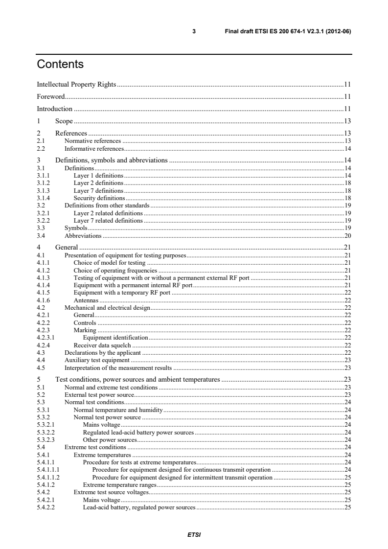
3 Final draft ETSI ES 200 674-1 V2.3.1 (2012-06)
Contents
Intellectual Property Rights . 11
Foreword . 11
Introduction . 11
1 Scope . 13
2 References . 13
2.1 Normative references . 13
2.2 Informative references . 14
3 Definitions, symbols and abbreviations . 14
3.1 Definitions . 14
3.1.1 Layer 1 definitions . 14
3.1.2 Layer 2 definitions . 18
3.1.3 Layer 7 definitions . 18
3.1.4 Security definitions . 18
3.2 Definitions from other standards . 19
3.2.1 Layer 2 related definitions . 19
3.2.2 Layer 7 related definitions . 19
3.3 Symbols . 19
3.4 Abbreviations . 20
4 General . 21
4.1 Presentation of equipment for testing purposes . 21
4.1.1 Choice of model for testing . 21
4.1.2 Choice of operating frequencies . 21
4.1.3 Testing of equipment with or without a permanent external RF port . 21
4.1.4 Equipment with a permanent internal RF port . 21
4.1.5 Equipment with a temporary RF port . 22
4.1.6 Antennas . 22
4.2 Mechanical and electrical design . 22
4.2.1 General . 22
4.2.2 Controls . 22
4.2.3 Marking . 22
4.2.3.1 Equipment identification . 22
4.2.4 Receiver data squelch . 22
4.3 Declarations by the applicant . 22
4.4 Auxiliary test equipment . 23
4.5 Interpretation of the measurement results . 23
5 Test conditions, power sources and ambient temperatures . 23
5.1 Normal and extreme test conditions . 23
5.2 External test power source. 23
5.3 Normal test conditions . 24
5.3.1 Normal temperature and humidity . 24
5.3.2 Normal test power source . 24
5.3.2.1 Mains voltage . 24
5.3.2.2 Regulated lead-acid battery power sources . 24
5.3.2.3 Other power sources . 24
5.4 Extreme test conditions . 24
5.4.1 Extreme temperatures . 24
5.4.1.1 Procedure for tests at extreme temperatures . 24
5.4.1.1.1 Procedure for equipment designed for continuous transmit operation . 24
5.4.1.1.2 Procedure for equipment designed for intermittent transmit operation . 25
5.4.1.2 Extreme temperature ranges . 25
5.4.2 Extreme test source voltages . 25
5.4.2.1 Mains voltage . 25
5.4.2.2 Lead-acid battery, regulated power sources . 25
ETSI
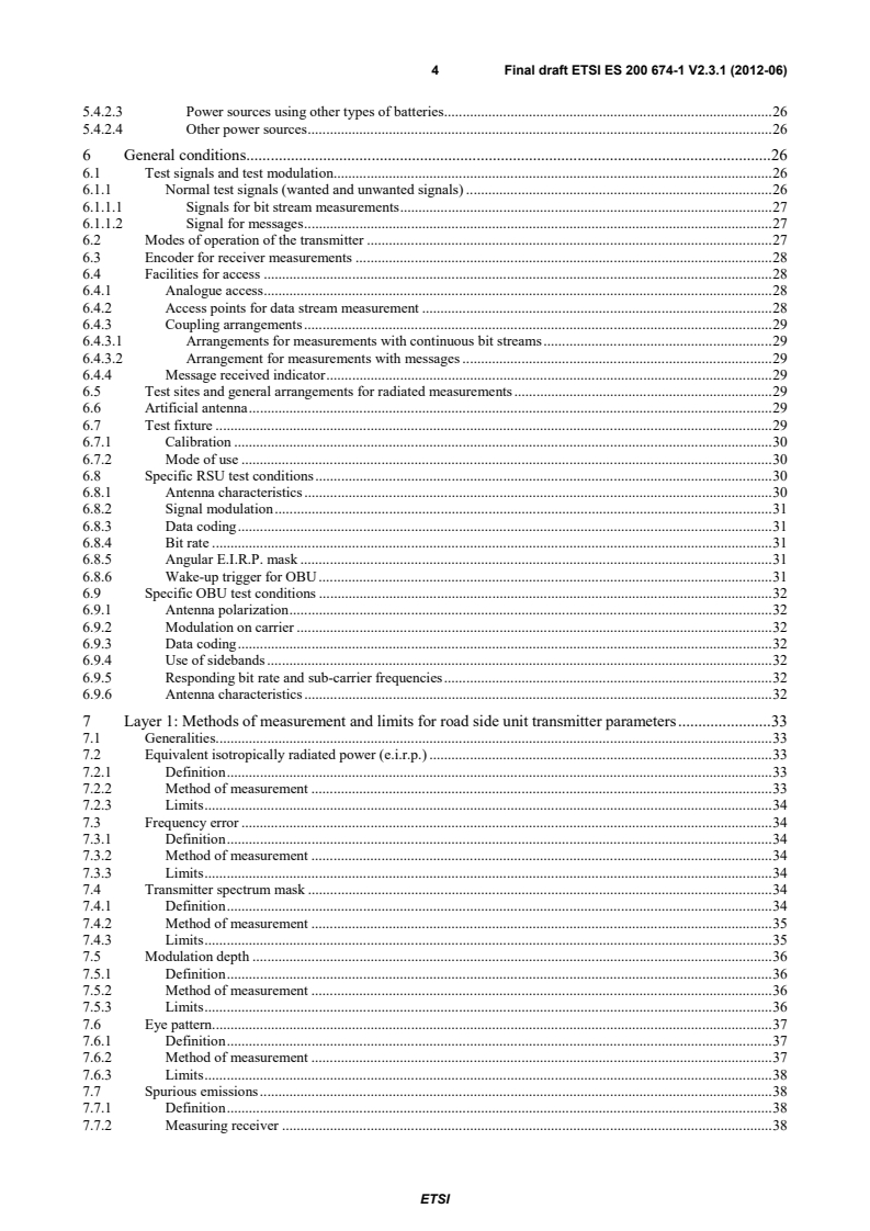
4 Final draft ETSI ES 200 674-1 V2.3.1 (2012-06)
5.4.2.3 Power sources using other types of batteries . 26
5.4.2.4 Other power sources . 26
6 General conditions . 26
6.1 Test signals and test modulation . 26
6.1.1 Normal test signals (wanted and unwanted signals) . 26
6.1.1.1 Signals for bit stream measurements . 27
6.1.1.2 Signal for messages . 27
6.2 Modes of operation of the transmitter . 27
6.3 Encoder for receiver measurements . 28
6.4 Facilities for access . 28
6.4.1 Analogue access . 28
6.4.2 Access points for data stream measurement . 28
6.4.3 Coupling arrangements . 29
6.4.3.1 Arrangements for measurements with continuous bit streams . 29
6.4.3.2 Arrangement for measurements with messages . 29
6.4.4 Message received indicator . 29
6.5 Test sites and general arrangements for radiated measurements . 29
6.6 Artificial antenna . 29
6.7 Test fixture . 29
6.7.1 Calibration . 30
6.7.2 Mode of use . 30
6.8 Specific RSU test conditions . 30
6.8.1 Antenna characteristics . 30
6.8.2 Signal modulation . 31
6.8.3 Data coding . 31
6.8.4 Bit rate . 31
6.8.5 Angular E.I.R.P. mask . 31
6.8.6 Wake-up trigger for OBU . 31
6.9 Specific OBU test conditions . 32
6.9.1 Antenna polarization . 32
6.9.2 Modulation on carrier . 32
6.9.3 Data coding . 32
6.9.4 Use of sidebands . 32
6.9.5 Responding bit rate and sub-carrier frequencies . 32
6.9.6 Antenna characteristics . 32
7 Layer 1: Methods of measurement and limits for road side unit transmitter parameters . 33
7.1 Generalities. 33
7.2 Equivalent isotropically radiated power (e.i.r.p.) . 33
7.2.1 Definition . 33
7.2.2 Method of measurement . 33
7.2.3 Limits . 34
7.3 Frequency error . 34
7.3.1 Definition . 34
7.3.2 Method of measurement . 34
7.3.3 Limits . 34
7.4 Transmitter spectrum mask . 34
7.4.1 Definition . 34
7.4.2 Method of measurement . 35
7.4.3 Limits . 35
7.5 Modulation depth . 36
7.5.1 Definition . 36
7.5.2 Method of measurement . 36
7.5.3 Limits . 36
7.6 Eye pattern. 37
7.6.1 Definition . 37
7.6.2 Method of measurement . 37
7.6.3 Limits . 38
7.7 Spurious emissions . 38
7.7.1 Definition . 38
7.7.2 Measuring receiver . 38
ETSI
5 Final draft ETSI ES 200 674-1 V2.3.1 (2012-06)
7.7.3 Method of measurement conducted spurious emission. 38
7.7.4 Method of measurement cabinet spurious radiation . 39
7.7.5 Method of measurement radiated spurious emission . 40
7.7.6 Limits . 40
8 Layer 1: Methods of measurement and limits for road side unit receiver parameters . 40
8.1 Maximum useable sensitivity . 41
8.1.1 Definition . 41
8.1.2 Method of measurements under normal and extreme test conditions . 41
8.1.2.1 Test arrangement for equipment with integral antenna . 41
8.1.2.2 Test arrangement for equipment with antenna connector . 42
8.1.2.3 Test procedure for continuous bit streams . 43
8.1.2.4 Test procedure for messages . 43
8.1.3 Limits . 43
8.2 Error behaviour at high wanted input signals . 43
8.2.1 Definition . 43
8.2.2 Method of measurement . 43
8.2.3 Limits . 44
8.3 Degradation measurements . 44
8.3.1 Definition . 44
8.3.2 General conditions . 44
8.3.3 Co-channel rejection . 45
8.3.3.1 Definition . 45
8.3.3.2 Method of measurement . 45
8.3.3.3 Limits . 46
8.3.4 Adjacent channel selectivity . 46
8.3.4.1 Definition . 46
8.3.4.2 Method of measurement . 46
8.3.4.3 Limits . 47
8.3.5 Spurious response rejection and blocking/desensitization . 47
8.3.5.1 Definition . 47
8.3.5.2 Method of measurement . 47
8.3.5.3 Limits . 48
8.3.6 Intermodulation response rejection . 48
8.3.6.1 Definition . 48
8.3.6.2 Method of measurement . 48
8.3.6.3 Limits . 49
8.4 Spurious emissions . 49
8.4.1 Definition . 49
8.4.2 Method of measurement - conducted spurious emissions . 49
8.4.3 Method of measurement - cabinet radiation . 50
8.4.4 Method of measurement - radiated spurious components . 50
8.4.5 Limits . 51
9 Layer 1: Method of measurements and limits for on-board units . 51
9.1 OBU sensitivity . 51
9.1.1 Definition . 51
9.1.2 Method of measurement . 51
9.1.3 Limits . 52
9.2 On board unit access. 52
9.2.1 Definition . 52
9.2.2 Method of measurement . 52
9.2.3 Limits . 54
9.3 Transponder conversion gain . 54
9.3.1 Definition . 54
9.3.2 Method of measurement . 54
9.3.3 Limits . 56
9.4 OBU maximum radiated subcarrier . 56
9.4.1 Definition . 56
9.4.2 Method of measurement . 56
9.4.3 Limits . 56
9.5 OBU frequency error . 57
ETSI
6 Final draft ETSI ES 200 674-1 V2.3.1 (2012-06)
9.5.1 Definition . 57
9.5.2 Method of measurement . 57
9.5.3 Limits . 58
9.6 OBU spurious radiation . 58
9.6.1 Definition . 58
9.6.2 Method of measurement . 58
9.6.3 Limits . 59
10 Layer 2 parameters and procedures . 59
10.1 General conditions . 59
10.2 Frame Structure . 59
10.2.1 Definition . 59
10.2.2 Limits . 60
10.2.2.1 Validity of frames . 60
10.2.2.2 Bit order . 60
10.2.2.3 Transparency . 60
10.2.2.4 Frame length . 60
10.3 Opening and closing flags . 60
10.3.1 Definition . 60
10.3.2 Limits . 61
10.4 LPDU . 61
10.4.1 Definition . 61
10.4.2 Limits . 61
10.5 Frame check sequence . 62
10.5.1 Definition . 62
10.5.2 Limits . 62
10.6 Frame transmission procedure . 62
10.7 Frame reception procedure . 62
10.8 Specific Road Side Unit parameters and procedures . 62
10.8.1 Link ID allocation . 62
10.8.2 Frame transmission . 63
10.8.3 Frame reception . 63
10.9 Specific On Board Units (OBUs) parameters and functions . 63
10.9.1 Link ID allocation . 63
10.9.2 Frame transmission . 63
10.9.3 Frame reception . 63
11 Layer 7 parameters and procedures . 64
11.1 General conditions . 64
11.2 General protocol rules . 64
11.2.1 Protocol data unit formats . 64
11.2.2 Concatenation . 64
11.2.3 Sessions . 64
11.3 Protocol messages and parameters: ASN.1 definitions . 65
11.4 Encoding rules . 69
11.4.1 Encoding of the primitive types . 70
11.4.1.1 BIT STRING type . 70
11.4.1.2 INTEGER type . 70
11.4.2 Encoding of the structured types . 70
11.4.2.1 SEQUENCE type . 70
11.4.2.2 SEQUENCE OF type . 70
11.4.2.3 CHOICE type . 70
11.4.2.4 SET type . 70
11.4.2.5 SET OF type. 70
11.5 RSU specific parameters and procedures . 71
11.5.1 Application protocol data unit formats . 71
11.5.2 Open-Rq directive . 71
11.5.2.1 Definition . 71
11.5.2.2 Method of measurement . 71
11.5.2.3 Limits . 72
11.5.3 Close-Rq directive . 72
11.5.3.1 Definition . 72
ETSI
7 Final draft ETSI ES 200 674-1 V2.3.1 (2012-06)
11.5.3.2 Method of measurement . 72
11.5.3.3 Limits . 72
11.5.4 Select-TBA-Id-Rq directive . 72
11.5.4.1 Definition . 72
11.5.4.2 Method of measurement . 72
11.5.4.3 Limits . 72
11.5.5 Read-Display-Type-Rq directive . 73
11.5.5.1 Definition . 73
11.5.5.2 Method of measurement . 73
11.5.5.3 Limits . 73
11.5.6 Read-Master-Core-Rq directive . 73
11.5.6.1 Definition . 73
11.5.6.2 Method of measurement . 73
11.5.6.3 Limits . 73
11.5.7 Get-Master-Record-Rq directive . 73
11.5.7.1 Definition . 73
11.5.7.2 Method of measurement . 73
11.5.6.3 Limits . 74
11.5.8 Read-Appl-Core-Rq directive . 74
11.5.8.1 Definition . 74
11.5.8.2 Method of measurement . 74
11.5.8.3 Limits . 74
11.5.9 Write-Appl-Core-Rq directive . 74
11.5.9.1 Definition . 74
11.5.9.2 Method of measurement . 74
11.5.9.3 Limits . 74
11.5.10 Write-Appl-Core-Conf-Rq directive . 75
11.5.10.1 Definition . 75
11.5.10.2 Method of measurement . 75
11.5.1
...
ETSI Standard
Intelligent Transport Systems (ITS);
Road Transport and Traffic Telematics (RTTT);
Dedicated Short Range Communications (DSRC);
Part 1: Technical characteristics and test methods for High
Data Rate (HDR) data transmission equipment operating in
the 5,8 GHz Industrial, Scientific and Medical (ISM) band
2 ETSI ES 200 674-1 V2.3.1 (2012-08)
Reference
RES/ITS-0020052
Keywords
DSRC, ITS, protocol, testing
ETSI
650 Route des Lucioles
F-06921 Sophia Antipolis Cedex - FRANCE
Tel.: +33 4 92 94 42 00 Fax: +33 4 93 65 47 16
Siret N° 348 623 562 00017 - NAF 742 C
Association à but non lucratif enregistrée à la
Sous-Préfecture de Grasse (06) N° 7803/88
Important notice
Individual copies of the present document can be downloaded from:
http://www.etsi.org
The present document may be made available in more than one electronic version or in print. In any case of existing or
perceived difference in contents between such versions, the reference version is the Portable Document Format (PDF).
In case of dispute, the reference shall be the printing on ETSI printers of the PDF version kept on a specific network drive
within ETSI Secretariat.
Users of the present document should be aware that the document may be subject to revision or change of status.
Information on the current status of this and other ETSI documents is available at
http://portal.etsi.org/tb/status/status.asp
If you find errors in the present document, please send your comment to one of the following services:
http://portal.etsi.org/chaircor/ETSI_support.asp
Copyright Notification
No part may be reproduced except as authorized by written permission.
The copyright and the foregoing restriction extend to reproduction in all media.
© European Telecommunications Standards Institute 2012.
All rights reserved.
TM TM TM
DECT , PLUGTESTS , UMTS and the ETSI logo are Trade Marks of ETSI registered for the benefit of its Members.
TM
3GPP and LTE™ are Trade Marks of ETSI registered for the benefit of its Members and
of the 3GPP Organizational Partners.
GSM® and the GSM logo are Trade Marks registered and owned by the GSM Association.
ETSI
3 ETSI ES 200 674-1 V2.3.1 (2012-08)
Contents
Intellectual Property Rights . 11
Foreword . 11
Introduction . 11
1 Scope . 13
2 References . 13
2.1 Normative references . 13
2.2 Informative references . 14
3 Definitions, symbols and abbreviations . 14
3.1 Definitions . 14
3.1.1 Layer 1 definitions . 14
3.1.2 Layer 2 definitions . 18
3.1.3 Layer 7 definitions . 18
3.1.4 Security definitions . 18
3.2 Definitions from other standards . 19
3.2.1 Layer 2 related definitions . 19
3.2.2 Layer 7 related definitions . 19
3.3 Symbols . 19
3.4 Abbreviations . 20
4 General . 21
4.1 Presentation of equipment for testing purposes . 21
4.1.1 Choice of model for testing . 21
4.1.2 Choice of operating frequencies . 21
4.1.3 Testing of equipment with or without a permanent external RF port . 21
4.1.4 Equipment with a permanent internal RF port . 22
4.1.5 Equipment with a temporary RF port . 22
4.1.6 Antennas . 22
4.2 Mechanical and electrical design . 22
4.2.1 General . 22
4.2.2 Controls . 22
4.2.3 Marking . 22
4.2.3.1 Equipment identification . 22
4.2.4 Receiver data squelch . 22
4.3 Declarations by the applicant . 23
4.4 Auxiliary test equipment . 23
4.5 Interpretation of the measurement results . 23
5 Test conditions, power sources and ambient temperatures . 23
5.1 Normal and extreme test conditions . 23
5.2 External test power source. 23
5.3 Normal test conditions . 24
5.3.1 Normal temperature and humidity . 24
5.3.2 Normal test power source . 24
5.3.2.1 Mains voltage . 24
5.3.2.2 Regulated lead-acid battery power sources . 24
5.3.2.3 Other power sources . 24
5.4 Extreme test conditions . 24
5.4.1 Extreme temperatures . 24
5.4.1.1 Procedure for tests at extreme temperatures . 24
5.4.1.1.1 Procedure for equipment designed for continuous transmit operation . 24
5.4.1.1.2 Procedure for equipment designed for intermittent transmit operation . 25
5.4.1.2 Extreme temperature ranges . 25
5.4.2 Extreme test source voltages . 25
5.4.2.1 Mains voltage . 25
5.4.2.2 Lead-acid battery, regulated power sources . 25
ETSI
4 ETSI ES 200 674-1 V2.3.1 (2012-08)
5.4.2.3 Power sources using other types of batteries . 26
5.4.2.4 Other power sources . 26
6 General conditions . 26
6.1 Test signals and test modulation . 26
6.1.1 Normal test signals (wanted and unwanted signals) . 26
6.1.1.1 Signals for bit stream measurements . 27
6.1.1.2 Signal for messages . 27
6.2 Modes of operation of the transmitter . 27
6.3 Encoder for receiver measurements . 28
6.4 Facilities for access . 28
6.4.1 Analogue access . 28
6.4.2 Access points for data stream measurement . 28
6.4.3 Coupling arrangements . 29
6.4.3.1 Arrangements for measurements with continuous bit streams . 29
6.4.3.2 Arrangement for measurements with messages . 29
6.4.4 Message received indicator . 29
6.5 Test sites and general arrangements for radiated measurements . 29
6.6 Artificial antenna . 29
6.7 Test fixture . 29
6.7.1 Calibration . 30
6.7.2 Mode of use . 30
6.8 Specific RSU test conditions . 30
6.8.1 Antenna characteristics . 30
6.8.2 Signal modulation . 31
6.8.3 Data coding . 31
6.8.4 Bit rate . 31
6.8.5 Angular E.I.R.P. mask . 31
6.8.6 Wake-up trigger for OBU . 31
6.9 Specific OBU test conditions . 32
6.9.1 Antenna polarization . 32
6.9.2 Modulation on carrier . 32
6.9.3 Data coding . 32
6.9.4 Use of sidebands . 32
6.9.5 Responding bit rate and sub-carrier frequencies . 32
6.9.6 Antenna characteristics . 32
7 Layer 1: Methods of measurement and limits for road side unit transmitter parameters . 33
7.1 Generalities. 33
7.2 Equivalent isotropically radiated power (e.i.r.p.) . 33
7.2.1 Definition . 33
7.2.2 Method of measurement . 33
7.2.3 Limits . 34
7.3 Frequency error . 34
7.3.1 Definition . 34
7.3.2 Method of measurement . 34
7.3.3 Limits . 34
7.4 Transmitter spectrum mask . 34
7.4.1 Definition . 34
7.4.2 Method of measurement . 35
7.4.3 Limits . 35
7.5 Modulation depth . 36
7.5.1 Definition . 36
7.5.2 Method of measurement . 36
7.5.3 Limits . 36
7.6 Eye pattern. 37
7.6.1 Definition . 37
7.6.2 Method of measurement . 37
7.6.3 Limits . 38
7.7 Spurious emissions . 38
7.7.1 Definition . 38
7.7.2 Measuring receiver . 38
ETSI
5 ETSI ES 200 674-1 V2.3.1 (2012-08)
7.7.3 Method of measurement conducted spurious emission. 38
7.7.4 Method of measurement cabinet spurious radiation . 39
7.7.5 Method of measurement radiated spurious emission . 40
7.7.6 Limits . 40
8 Layer 1: Methods of measurement and limits for road side unit receiver parameters . 40
8.1 Maximum useable sensitivity . 41
8.1.1 Definition . 41
8.1.2 Method of measurements under normal and extreme test conditions . 41
8.1.2.1 Test arrangement for equipment with integral antenna . 41
8.1.2.2 Test arrangement for equipment with antenna connector . 42
8.1.2.3 Test procedure for continuous bit streams . 43
8.1.2.4 Test procedure for messages . 43
8.1.3 Limits . 43
8.2 Error behaviour at high wanted input signals . 43
8.2.1 Definition . 43
8.2.2 Method of measurement . 43
8.2.3 Limits . 44
8.3 Degradation measurements . 44
8.3.1 Definition . 44
8.3.2 General conditions . 44
8.3.3 Co-channel rejection . 45
8.3.3.1 Definition . 45
8.3.3.2 Method of measurement . 45
8.3.3.3 Limits . 46
8.3.4 Adjacent channel selectivity . 46
8.3.4.1 Definition . 46
8.3.4.2 Method of measurement . 46
8.3.4.3 Limits . 47
8.3.5 Spurious response rejection and blocking/desensitization . 47
8.3.5.1 Definition . 47
8.3.5.2 Method of measurement . 47
8.3.5.3 Limits . 48
8.3.6 Intermodulation response rejection . 48
8.3.6.1 Definition . 48
8.3.6.2 Method of measurement . 48
8.3.6.3 Limits . 49
8.4 Spurious emissions . 49
8.4.1 Definition . 49
8.4.2 Method of measurement - conducted spurious emissions . 49
8.4.3 Method of measurement - cabinet radiation . 50
8.4.4 Method of measurement - radiated spurious components . 50
8.4.5 Limits . 51
9 Layer 1: Method of measurements and limits for on-board units . 51
9.1 OBU sensitivity . 51
9.1.1 Definition . 51
9.1.2 Method of measurement . 51
9.1.3 Limits . 52
9.2 On board unit access. 52
9.2.1 Definition . 52
9.2.2 Method of measurement . 52
9.2.3 Limits . 54
9.3 Transponder conversion gain . 54
9.3.1 Definition . 54
9.3.2 Method of measurement . 54
9.3.3 Limits . 56
9.4 OBU maximum radiated subcarrier . 56
9.4.1 Definition . 56
9.4.2 Method of measurement . 56
9.4.3 Limits . 56
9.5 OBU frequency error . 57
ETSI
6 ETSI ES 200 674-1 V2.3.1 (2012-08)
9.5.1 Definition . 57
9.5.2 Method of measurement . 57
9.5.3 Limits . 58
9.6 OBU spurious radiation . 58
9.6.1 Definition . 58
9.6.2 Method of measurement . 58
9.6.3 Limits . 59
10 Layer 2 parameters and procedures . 59
10.1 General conditions . 59
10.2 Frame Structure . 59
10.2.1 Definition . 59
10.2.2 Limits . 60
10.2.2.1 Validity of frames . 60
10.2.2.2 Bit order . 60
10.2.2.3 Transparency . 60
10.2.2.4 Frame length . 60
10.3 Opening and closing flags . 60
10.3.1 Definition . 60
10.3.2 Limits . 61
10.4 LPDU . 61
10.4.1 Definition . 61
10.4.2 Limits . 61
10.5 Frame check sequence . 62
10.5.1 Definition . 62
10.5.2 Limits . 62
10.6 Frame transmission procedure . 62
10.7 Frame reception procedure . 62
10.8 Specific Road Side Unit parameters and procedures . 62
10.8.1 Link ID allocation . 62
10.8.2 Frame transmission . 63
10.8.3 Frame reception . 63
10.9 Specific On Board Units (OBUs) parameters and functions . 63
10.9.1 Link ID allocation . 63
10.9.2 Frame transmission . 63
10.9.3 Frame reception . 63
11 Layer 7 parameters and procedures . 64
11.1 General conditions . 64
11.2 General protocol rules . 64
11.2.1 Protocol data unit formats . 64
11.2.2 Concatenation . 64
11.2.3 Sessions . 64
11.3 Protocol messages and parameters: ASN.1 definitions . 65
11.4 Encoding rules . 69
11.4.1 Encoding of the primitive types . 70
11.4.1.1 BIT STRING type . 70
11.4.1.2 INTEGER type . 70
11.4.2 Encoding of the structured types . 70
11.4.2.1 SEQUENCE type . 70
11.4.2.2 SEQUENCE OF type . 70
11.4.2.3 CHOICE type . 70
11.4.2.4 SET type . 70
11.4.2.5 SET OF type. 70
11.5 RSU specific parameters and procedures . 71
11.5.1 Application protocol data unit formats . 71
11.5.2 Open-Rq directive . 71
11.5.2.1 Definition . 71
11.5.2.2 Method of measurement . 71
11.5.2.3 Limits . 72
11.5.3 Close-Rq directive . 72
11.5.3.1 Definition . 72
ETSI
7 ETSI ES 200 674-1 V2.3.1 (2012-08)
11.5.3.2 Method of measurement . 72
11.5.3.3 Limits . 72
11.5.4 Select-TBA-Id-Rq directive . 72
11.5.4.1 Definition . 72
11.5.4.2 Method of measurement . 72
11.5.4.3 Limits . 72
11.5.5 Read-Display-Type-Rq directive . 73
11.5.5.1 Definition . 73
11.5.5.2 Method of measurement . 73
11.5.5.3 Limits . 73
11.5.6 Read-Master-Core-Rq directive . 73
11.5.6.1 Definition . 73
11.5.6.2 Method of measurement . 73
11.5.6.3 Limits . 73
11.5.7 Get-Master-Record-Rq directive . 73
11.5.7.1 Definition . 73
11.5.7.2 Method of measurement . 73
11.5.6.3 Limits . 74
11.5.8 Read-Appl-Core-Rq directive . 74
11.5.8.1 Definition . 74
11.5.8.2 Method of measurement . 74
11.5.8.3 Limits . 74
11.5.9 Write-Appl-Core-Rq directive . 74
11.5.9.1 Definition . 74
11.5.9.2 Method of measurement . 74
11.5.9.3 Limits . 74
11.5.10 Write-Appl-Core-Conf-Rq directive . 75
11.5.10.1 Definition . 75
11.5.10.2 Method of measurement . 75
11.5.10.3 Limits .
...