

SIST EN 16727-2-1:2026
(Main)Railway applications - Track - Noise barriers and related devices acting on airborne sound propagation - Non-acoustic performance - Part 2-1: Mechanical performance under dynamic loadings due to passing trains - Resistance to fatigue
- Abstract
This document describes the basic requirements for the verification of ultimate and serviceability limit states and the resistance to fatigue either of the noise barrier or its components by means of analytical methods and/or tests.
Analytical methods can be used for the determination of the characteristic values and design values.
Where sufficient information is not available, the analytical procedure can be combined with results from tests.
This document provides the following types of test procedures:
- test on small samples for defining detail categories, which might not be covered by Eurocodes (verification procedure A);
- test on a global element for defining the limit state against fatigue (verification procedure B);
- full scale tests under a given representative loading (verification procedure C) to determine fatigue resistance of the noise barrier components for defined loading conditions; verification procedure C is given as alternative to verification procedures A and B.
- Status
- Published
- Public Enquiry End Date
- 30-Nov-2025
- Publication Date
- 04-Oct-2026
- Technical Committee
- IŽNP - Reilway applications
- Current Stage
- 6060 - National Implementation/Publication (Adopted Project)
- Start Date
- 01-Oct-2026
- Due Date
- 06-Dec-2026
- Completion Date
- 05-Oct-2026


SIST EN 16727-2-1:2026 is the Slovenian adoption of EN 16727-2-1:2026 from CEN for railway noise barriers and related devices acting on airborne sound propagation. It specifies how to verify mechanical performance under dynamic loadings from passing trains, with a focus on resistance to fatigue, using calculation methods and tests for designers, manufacturers, laboratories, and infrastructure authorities.
What does SIST EN 16727-2-1:2026 specify?
SIST EN 16727-2-1:2026 sets the basic requirements for checking ultimate limit states, serviceability limit states, and fatigue resistance of a noise barrier or its components. It does this through analytical verification, testing, or a combination of both, so the user can choose a route that matches the available design data and test evidence.
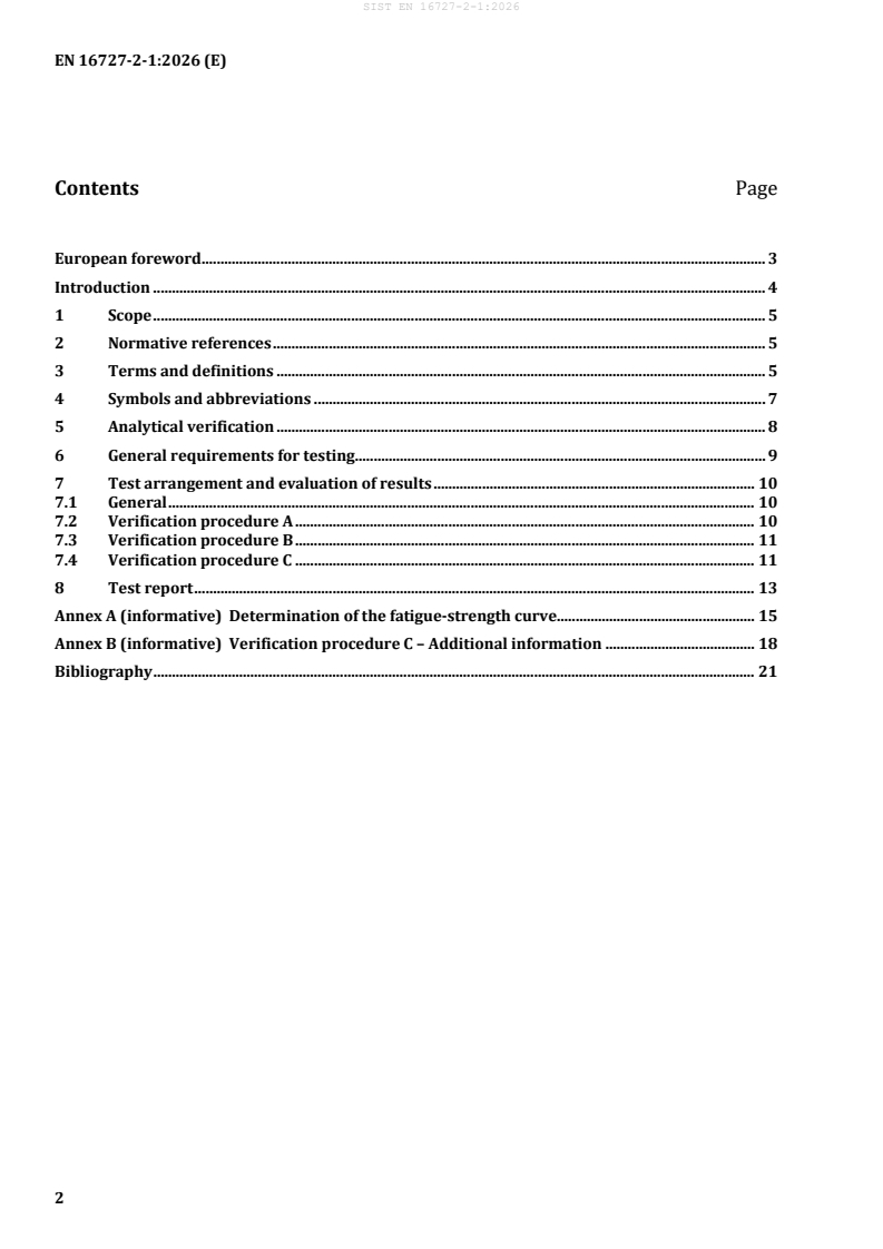
The document is organized into Clauses 1 to 8, covering scope, normative references, terms and definitions, symbols and abbreviations, analytical verification, test requirements, test arrangement and evaluation, and the test report. Annex A explains how to derive the fatigue-strength curve, and Annex B gives additional guidance for verification procedure C.
| Annex | What it covers |
|---|---|
| Annex A | Determination of the fatigue-strength curve and characteristic fatigue strength values |
| Annex B | Additional information for verification procedure C, including test equipment and loading arrangement |
What are the key requirements of SIST EN 16727-2-1:2026?
Analytical verification
- Clause 5 says analytical design may be used for foundations, posts, and panels, with verification according to the relevant Eurocodes or an EAD. In practice, this means the design route must match the material and product type, not just the overall structure.
- For steel and aluminium, Clause 5 points to the EN 1993 series and EN 1999 series, and for concrete it points to the EN 1992 series. The clause also highlights fatigue-sensitive details such as fasteners, support areas, profiled sheets, material combinations, and cold-formed sections. This matters because fatigue often starts in a local detail rather than in the main member.
- Clause 5 also requires consideration of combined actions such as bending, vertical shear, torsion, and anchorage behaviour. For concrete, it specifically brings in reinforcement anchorage, shear at the panel end, and possible separation of a porous layer from the supporting concrete layer. In practice, the engineer has to check the weak points where service loads become repeated damage.
Test planning and verification procedures
- Clause 6 requires a complete information package before testing, including the intended use, railway parameters, geometry, load transfer, torsional behaviour, drawings, photos, material certificates, the specimen condition, and the method for evaluating results. This is what makes the test result traceable and usable for design or approval.
- Clause 7.1 requires deformation-controlled static tests according to EN 16727-1 to confirm that the structural model reflects real behaviour, and it requires measurement at significant points on both faces of the element. It also requires attention to torsion and end twisting where they influence the panel. In practice, the test setup must represent the way the barrier actually bends, twists, and transfers load on site.
- Verification procedure A in Clause 7.2 is for small samples and detail categories. It is used to derive the fatigue-strength curve for a local detail, especially when a detail is not covered by Eurocode classification. That matters when a manufacturer needs to qualify a specific fastener, joint, or sheet detail.
- Verification procedure B in Clause 7.3 is for a global element. It separates assessment of bending at mid-span from vertical shear and bearing at supports, and it requires extra work if torsion, end twisting, or local load introduction affect fatigue resistance. This procedure is used when the question is whether the whole panel or element can withstand repeated train-induced loading.
- Verification procedure C in Clause 7.4 is for acoustic elements and special components under representative loading defined by the Infrastructure Manager or the relevant Authority. It uses the actual assembly of acoustic elements, fasteners, screws, gaskets, and frames, but not the supporting posts. In practice, this procedure checks whether the product behaves correctly as installed, not just as separate parts.
Evaluation and reporting
- Clause 7 says the test evaluation looks at visible cracking, plastic deformation, excessive gaps, strain histories, load histories, and the failure mode. The result is only meaningful if the same failure mode is compared across tests.
- Clause 8 requires the report to include the design basis, the specimen description, the loading arrangement, measurement data, failure descriptions, plots of load versus deformation and strain, and the evidence used to derive characteristic and design fatigue values. For procedure A it also requires the fatigue-strength curve and the stress-range model; for procedure B it adds statistical treatment and stiffness development with load cycles; for procedure C it adds the detailed product description, apparatus description, measurement results, and visual inspection results after each phase.
What terms does SIST EN 16727-2-1:2026 define?
- Noise barrier - a noise reducing device that blocks direct airborne sound from railways and is typically installed between posts, sometimes with an overhang.
- Cladding - a noise reducing device attached to a wall or other structure to reduce reflected sound.
- Acoustic element - the part whose main function is to provide acoustic performance.
- Structural element - the part whose main function is to support or hold acoustic elements in place.
- Added device - an extra component that affects the acoustic performance of the original noise-reducing device, mainly through diffracted energy.
- Representative loading - loading that reflects train air pressure waves together with site conditions, dynamic amplification, and fatigue damage accumulation.
Who uses SIST EN 16727-2-1:2026?
SIST EN 16727-2-1:2026 is used by railway infrastructure managers, noise barrier manufacturers, structural engineers, test laboratories, and assessment bodies. It is relevant to anyone who has to design, verify, test, or accept trackside noise barriers and related devices for fatigue resistance under passing trains.
Typical uses include:
- selecting analytical verification or a test route
- defining test specimens and loading arrangements
- checking fatigue resistance of panels, posts, fasteners, and joints
- preparing technical files and test reports
- comparing design calculations with measured behaviour
What changed in SIST EN 16727-2-1:2026 from the previous edition?
SIST EN 16727-2-1:2026 supersedes EN 16727-2-1:2018.
Which standards are used with SIST EN 16727-2-1:2026?
- EN 1990-1:2023+A1:2026 - provides the basis for structural and geotechnical design and is used for the statistical treatment of fatigue resistance.
- EN 1992 (all parts) - provides the design rules for concrete structures used in analytical verification.
- EN 1993 (all parts) - provides the design rules for steel structures used in analytical verification.
- EN 1999 (all parts) - provides the design rules for aluminium structures used in analytical verification and fatigue evaluation.
- EN 16727-1 - provides the static load calculation and test method used for the deformation checks that support fatigue verification.
- EN 16727-2-2 - is the companion part intended to be read with this document for calculation of mechanical performance under dynamic loadings.
- EAD - is mentioned for cases where analytical design uses a European Assessment Document for products not fully covered by a harmonised European standard.
What does the SIST EN 16727-2-1:2026 document contain?
The document includes a symbols-and-abbreviations table, test planning requirements, and detailed descriptions of three verification procedures. Annex A gives the statistical method for deriving the mean S-N curve, the characteristic fatigue strength at 2 million load cycles, and the related confidence treatment. Annex B describes a practical test rig with vertical supports, actuators, displacement measurement, and arrangements for bending and torsional testing, including guidance on load application, inspection, and photographic reporting.
It also contains the reporting content needed to document materials, specimens, loading, measurements, failures, and the relationship between load cycles and deformation or stiffness. For a reader, this means the standard is not only a design aid but also a checklist for building a defensible fatigue test file.
Relations
- Effective Date
- 01-Nov-2026
- Effective Date
- 07-Oct-2026
- Refers
kSIST FprEN 1993-1-11:2025 - Eurocode 3 - Design of steel structures - Part 1-11: Tension components - Effective Date
- 07-Oct-2026
Get Certified
Connect with accredited certification bodies for this standard

BSMI (Bureau of Standards, Metrology and Inspection)
Taiwan's standards and inspection authority.
Zavod za gradbeništvo Slovenije (ZAG) - Inšpekcija
ZAG inspection body for construction products, structures, and materials.
Sponsored listings
Frequently Asked Questions
SIST EN 16727-2-1:2026 is a standard published by the Slovenian Institute for Standardization (SIST). Its full title is "Railway applications - Track - Noise barriers and related devices acting on airborne sound propagation - Non-acoustic performance - Part 2-1: Mechanical performance under dynamic loadings due to passing trains - Resistance to fatigue". This standard covers: This document describes the basic requirements for the verification of ultimate and serviceability limit states and the resistance to fatigue either of the noise barrier or its components by means of analytical methods and/or tests. Analytical methods can be used for the determination of the characteristic values and design values. Where sufficient information is not available, the analytical procedure can be combined with results from tests. This document provides the following types of test procedures: - test on small samples for defining detail categories, which might not be covered by Eurocodes (verification procedure A); - test on a global element for defining the limit state against fatigue (verification procedure B); - full scale tests under a given representative loading (verification procedure C) to determine fatigue resistance of the noise barrier components for defined loading conditions; verification procedure C is given as alternative to verification procedures A and B.
This document describes the basic requirements for the verification of ultimate and serviceability limit states and the resistance to fatigue either of the noise barrier or its components by means of analytical methods and/or tests. Analytical methods can be used for the determination of the characteristic values and design values. Where sufficient information is not available, the analytical procedure can be combined with results from tests. This document provides the following types of test procedures: - test on small samples for defining detail categories, which might not be covered by Eurocodes (verification procedure A); - test on a global element for defining the limit state against fatigue (verification procedure B); - full scale tests under a given representative loading (verification procedure C) to determine fatigue resistance of the noise barrier components for defined loading conditions; verification procedure C is given as alternative to verification procedures A and B.
SIST EN 16727-2-1:2026 is classified under the following ICS (International Classification for Standards) categories: 17.140.30 - Noise emitted by means of transport; 93.100 - Construction of railways. The ICS classification helps identify the subject area and facilitates finding related standards.
SIST EN 16727-2-1:2026 has the following relationships with other standards: It is inter standard links to SIST EN 16727-2-1:2018, kSIST FprEN 1993-1-1:2022, kSIST FprEN 1993-1-11:2025. Understanding these relationships helps ensure you are using the most current and applicable version of the standard.
SIST EN 16727-2-1:2026 is available in PDF format for immediate download after purchase. The document can be added to your cart and obtained through the secure checkout process. Digital delivery ensures instant access to the complete standard document.
Standards Content (Sample)
SLOVENSKI STANDARD
01-november-2026
Nadomešča:
SIST EN 16727-2-1:2018
Železniške naprave - Zgornji ustroj proge - Protihrupne ovire in pripadajoče
naprave, ki vplivajo na širjenje zvoka v zraku - Neakustične lastnosti - 2-1. del:
Mehanske lastnosti pri dinamičnih obremenitvah zaradi mimo vozečih vlakov -
Odpornost proti utrujanju
Railway applications - Track - Noise barriers and related devices acting on airborne
sound propagation - Non-acoustic performance - Part 2-1: Mechanical performance
under dynamic loadings due to passing trains - Resistance to fatigue
Bahnanwendungen - Oberbau - Lärmschutzwände und verwandte Vorrichtungen zur
Beeinflussung der Luftschallausbreitung - Nicht akustische Eigenschaften - Teil 2-1:
Mechanische Eigenschaftsanforderungen unter dynamischen Belastungen aufgrund
vorbeifahrender Züge - Prüfverfahren zum Ermüdungsverhalten
Applications ferroviaires - Voie - Écrans antibruit et dispositifs connexes influant sur la
propagation aérienne du son - Performances non acoustiques - Partie 2-1 : Tenue
mécanique sous charges dynamiques dues à la circulation ferroviaire - Résistance à
fatigue
Ta slovenski standard je istoveten z: EN 16727-2-1:2026
ICS:
17.140.30 Emisija hrupa transportnih Noise emitted by means of
sredstev transport
93.100 Gradnja železnic Construction of railways
2003-01.Slovenski inštitut za standardizacijo. Razmnoževanje celote ali delov tega standarda ni dovoljeno.
EN 16727-2-1
EUROPEAN STANDARD
NORME EUROPÉENNE
September 2026
EUROPÄISCHE NORM
ICS 93.100 Supersedes EN 16727-2-1:2018
English Version
Railway applications - Track - Noise barriers and related
devices acting on airborne sound propagation - Non-
acoustic performance - Part 2-1: Mechanical performance
under dynamic loadings due to passing trains - Resistance
to fatigue
Applications ferroviaires - Voie - Écrans antibruit et Bahnanwendungen - Oberbau - Lärmschutzwände und
dispositifs connexes influant sur la propagation verwandte Vorrichtungen zur Beeinflussung der
aérienne du son - Performances non acoustiques - Luftschallausbreitung - Nicht akustische Eigenschaften
Partie 2-1 : Tenue mécanique sous charges - Teil 2-1: Mechanische Eigenschaftsanforderungen
dynamiques dues à la circulation ferroviaire - unter dynamischen Belastungen aufgrund
Résistance à la fatigue vorbeifahrender Züge - Prüfverfahren zum
Ermüdungsverhalten
This European Standard was approved by CEN on 3 August 2026.
CEN members are bound to comply with the CEN/CENELEC Internal Regulations which stipulate the conditions for giving this
European Standard the status of a national standard without any alteration. Up-to-date lists and bibliographical references
concerning such national standards may be obtained on application to the CEN-CENELEC Management Centre or to any CEN
member.
This European Standard exists in three official versions (English, French, German). A version in any other language made by
translation under the responsibility of a CEN member into its own language and notified to the CEN-CENELEC Management
Centre has the same status as the official versions.
CEN members are the national standards bodies of Austria, Belgium, Bulgaria, Croatia, Cyprus, Czech Republic, Denmark, Estonia,
Finland, France, Germany, Greece, Hungary, Iceland, Ireland, Italy, Latvia, Lithuania, Luxembourg, Malta, Netherlands, Norway,
Poland, Portugal, Republic of North Macedonia, Romania, Serbia, Slovakia, Slovenia, Spain, Sweden, Switzerland, Türkiye and
United Kingdom.
EUROPEAN COMMITTEE FOR STANDARDIZATION
COMITÉ EUROPÉEN DE NORMALISATION
EUROPÄISCHES KOMITEE FÜR NORMUNG
CEN-CENELEC Management Centre: Rue de la Science 23, B-1040 Brussels
© 2026 CEN All rights of exploitation in any form and by any means reserved Ref. No. EN 16727-2-1:2026 E
worldwide for CEN national Members.
Contents Page
European foreword . 3
Introduction . 4
1 Scope . 5
2 Normative references . 5
3 Terms and definitions . 5
4 Symbols and abbreviations . 7
5 Analytical verification . 8
6 General requirements for testing . 9
7 Test arrangement and evaluation of results . 10
7.1 General . 10
7.2 Verification procedure A . 10
7.3 Verification procedure B . 11
7.4 Verification procedure C . 11
8 Test report . 13
Annex A (informative) Determination of the fatigue-strength curve . 15
Annex B (informative) Verification procedure C – Additional information . 18
Bibliography . 21
European foreword
This document (EN 16727-2-1:2026) has been prepared by Technical Committee CEN/TC 256 “Railway
Applications”, the secretariat of which is held by DIN.
This European Standard shall be given the status of a national standard, either by publication of an
identical text or by endorsement, at the latest by March 2027, and conflicting national standards shall be
withdrawn at the latest by March 2027.
Attention is drawn to the possibility that some of the elements of this document may be the subject of
patent rights. CEN shall not be held responsible for identifying any or all such patent rights.
This document supersedes EN 16727-2-1:2018.
This document is one of the series EN 16727, Railway applications — Track — Noise barriers and related
devices acting on airborne sound propagation — Non-acoustic performance, as listed below:
— Part 1: Mechanical performance under static loadings — Calculation and test method;
— Part 2-1: Mechanical performance under dynamic loadings due to passing trains — Resistance to
fatigue [this document];
— Part 2-2: Mechanical performance under dynamic loadings caused by passing trains — Calculation
method;
— Part 3: General safety and environmental requirements.
This document is intended to be read in conjunction with:
— EN 16727-1, Railway applications — Track — Noise barriers and related devices acting on airborne
sound propagation — Non-acoustic performance — Part 1: Mechanical performance under static
loadings — Calculation and test method;
— EN 16727-2-2, Railway applications — Track — Noise barriers and related devices acting on airborne
sound propagation — Non-acoustic performance — Part 2-2: Mechanical performance under dynamic
loadings caused by passing trains — Calculation method.
Any feedback and questions on this document should be directed to the users’ national standards body.
A complete listing of these bodies can be found on the CEN website.
According to the CEN-CENELEC Internal Regulations, the national standards organisations of the
following countries are bound to implement this European Standard: Austria, Belgium, Bulgaria, Croatia,
Cyprus, Czech Republic, Denmark, Estonia, Finland, France, Germany, Greece, Hungary, Iceland, Ireland,
Italy, Latvia, Lithuania, Luxembourg, Malta, Netherlands, Norway, Poland, Portugal, Republic of North
Macedonia, Romania, Serbia, Slovakia, Slovenia, Spain, Sweden, Switzerland, Türkiye and the United
Kingdom.
Introduction
Passing trains generate an air pressure wave, which impacts noise barriers installed alongside the track.
It is important that noise barriers withstand this impact without any part of them becoming detached or
displaced in an unsafe manner; they should be designed for the specified requirements in ultimate,
serviceability and fatigue limit states. Where no design rules or sufficient experience with components
are available, the design should be based on calculation and/or tests carried out in a way that provides
information on the properties of the component for design in ultimate and serviceability limit states and
the resistance to fatigue of noise barrier components or noise barriers considered as a whole.
1 Scope
This document describes the basic requirements for the verification of ultimate and serviceability limit
states and the resistance to fatigue either of the noise barrier or its components by means of analytical
methods and/or tests.
Analytical methods can be used for the determination of the characteristic values and design values.
Where sufficient information is not available, the analytical procedure can be combined with results from
tests.
This document provides the following types of test procedures:
— test on small samples for defining detail categories, which might not be covered by Eurocodes
(verification procedure A);
— test on a global element for defining the limit state against fatigue (verification procedure B);
— full scale tests under a given representative loading (verification procedure C) to determine fatigue
resistance of the noise barrier components for defined loading conditions; verification procedure C
is given as alternative to verification procedures A and B.
2 Normative references
The following documents are referred to in the text in such a way that some or all of their content
constitutes requirements of this document. For dated references, only the edition cited applies. For
undated references, the latest edition of the referenced document (including any amendments) applies.
EN 1990-1:2023+A1:2026, Eurocode - Basis of structural and geotechnical design - Part 1: New structures
EN 1992 (all parts), Eurocode 2: Design of concrete structures
EN 1993 (all parts), Eurocode 3 — Design of steel structures
EN 1999 (all parts), Eurocode 9: Design of aluminium structures
EN 16727-1, Railway applications - Track - Noise barriers and related devices acting on airborne sound
propagation - Non-acoustic performance - Part 1: Mechanical performance under static loadings -
Calculation and test method
3 Terms and definitions
For the purposes of this document, the following terms and definitions apply.
ISO and IEC maintain terminology databases for use in standardization at the following addresses:
• ISO Online browsing platform: available at https://www.iso.org/obp
• IEC Electropedia: available at https://www.electropedia.org/
3.1
noise barrier
noise reducing device, which obstructs the direct transmission of airborne sound emanating from
railways, and which will typically span between posts and also may overhang the railway
Note 1 to entry: Noise barriers are generally made of acoustic and structural elements (3.3 and 3.4).
3.2
cladding
noise reducing device, which is attached to a wall or other structure and reduces the amount of sound
reflected
Note 1 to entry: Claddings are generally made of acoustic and structural elements (3.3 and 3.4).
3.3
acoustic element
element whose primary function is to provide the acoustic performance of the device
3.4
structural element
element whose primary function is to support or hold in place acoustic elements
Note 1 to entry: In some noise barriers, the acoustic function and the structural function cannot be clearly
separated and attributed to different components.
3.5
added device
added component that influences the acoustic performance of the original noise-reducing device (acting
primarily on the diffracted energy)
Note 1 to entry: In some noise barriers, the acoustic function and the structural function cannot be clearly
separated and attributed to different components.
3.6
representative loading
loading which takes into account the load effects caused by the air pressure wave of the train, the site-
dependent parameters, the dynamic amplification factor and the fatigue stress behaviour of the
component, including the fatigue damage accumulation
Note 1 to entry: Examples of site-dependent parameters are: the design life, the number of trains per day, the
maximum train speed, the spacing between the noise barrier and the rail track.
4 Symbols and abbreviations
For the purposes of this document, the symbols and abbreviations in Table 1 apply.
Table 1 — Symbols and abbreviations
Symbol or
Designation Unit
abbreviation
a term for the representation of the mean value (50 % exceedance probability)
-
of the S-N curve on a logarithmic scale
a auxiliary parameter -
k
m factor for the representation of the mean value (50 % exceedance
-
probability) of the S-N curve on a logarithmic scale
Δσ single value of the stress range Pa
i
Δσ , stress range at 2 million load cycles, mean value Pa
c m
Δσ , characteristic value of the fatigue strength at 2 million load cycles Pa
c k
Δσ stress range of the S-N-curve Pa
R
N single value of the number of load cycles -
i
N number of 2 million load cycles -
c
N spread around the mean value under the assumption of a Student-t
c,k
-
distribution
N number of load cycles of the S-N-curve -
R
x log Δσ -
i i
y log N -
i i
mean value of x
i -
X
y
mean value of y
i -
n number of specimens -
S variance of the random variable x -
xx i
S variance of the random variable y -
yy i
S covariance of the random variables x and y -
xy i i
S standard deviation -
N
f auxiliary parameter for the representation of the 95 % confidence interval
-
derived from the S-N curve on a logarithmic scale
x auxiliary parameter -
c
t(α) parameter describing the Student-t Distribution with (n-2) degrees of
-
freedom and a 95 % confidence interval
5 Analytical verification
Where the design can be performed by analytical models, the verification for the foundations, posts and
panels shall be in accordance with Eurocodes or European Assessment Document (EAD) .
Steel and aluminium elements shall be designed in accordance with the relevant part of Eurocode 3,
i.e. the EN 1993 series, and Eurocode 9, i.e. the EN 1999 series. In particular, the following aspects shall
be considered:
a) behaviour of all relevant details and the whole panel for alternating loading conditions and the
corresponding frequency range;
b) failure of fasteners subject to multiple axial stress condition, e.g. shear from global bending and
tension from local load effects;
c) interaction of bending, vertical shear and torsion;
d) behaviour of the panel and the bearings at the support area considering secondary load paths;
e) fatigue resistance of profiled, perforated and coated thin metal sheets;
f) consideration of different material-combinations, e.g. aluminium linked with stainless steel;
g) fatigue strength of cold-formed elements and cross-sections considering local load effects.
The analytical verification of concrete elements shall be performed in accordance with the EN 1992 series
for bending, shear and torsion as well as for bearing conditions at the uprights and for the anchoring of
the reinforcement. In particular, the following aspects shall be considered:
h) anchoring of the longitudinal reinforcement at the end support taking into account the anchoring
length according to the EN 1992 series;
i) verification of the ultimate limit state and the fatigue limit state for the shear force and the end
anchorage at the end of the panel for alternating actions;
j) verification of the ultimate limit state against fatigue of the porous layer of the panel (if any) against
bonding failure in the interface and separation from the supporting concrete layer.
European Assessment Document (EAD), established by the European Organisation for Technical Assessment (EOTA) as the
basis for European Technical Assessments (ETAs) for construction products that are not or not fully covered by a harmonised
European standard (hEN) under the Construction Products Regulation (EU) 3110/2024. Freely available at
https://www.eota.eu/.
6 General requirements for testing
The following information shall be provided before testing:
a) scope for the use of the noise barrier or of its components;
b) relevant railway and construction parameters (designed speed, traffic density, train types, maximum
wall height, minimum distance to track, spacing of uprights, foundation type, wind zone, etc.);
c) description of the noise barrier or components and of the global and local load transfer and bearing
behaviour;
d) information about the torsional behaviour (torsional stiffness and stresses) of the component caused
by end twisting;
e) drawings of the relevant noise barrier components including all details and information about
tolerances;
f) photographic information of all construction details;
g) informative documents and certificates of used materials and fasteners, and the required material
tests and the relevant standards to define the material properties;
h) description of test programme and test specimens; the structural supporting of the elements shall be
in accordance with on-site conditions;
i) method for the evaluation of test results and for the determination of the characteristic and design
values of resistance against fatigue in accordance with the EN 1999 series and Annex B of this
document;
j) description of the load arrangement and load application: the load arrangement should be
comparable with site conditions taking into account the effect of distributed loads due to the pressure
wave and torsional deformations caused by the flexibility of the supporting posts; the influence of
torsion may be neglected in testing if at critical points the increase of stresses due to torsion does not
exceed 10 % of the corresponding stresses due to bending;
k) test measuring setup with information about measurement devices for deformations and strains;
l) specification of the representative loading in the case of use of verification procedure C;
m) specification of the state of the sample: new or aged, condition of ageing (e.g. natural or accelerated,
chemical, mechanical, UV radiation, etc.).
7 Test arrangement and evaluation of results
7.1 General
In order to verify that the structural model used in verification procedures A and B is in accordance with
the real behaviour of the element, two deformation-controlled static tests according to EN 16727-1 shall
be carried out, taking into account the different mechanical behaviour of the two sides of the element
(conventionally denoted as “facing the train” and “facing the receivers”). The sample under test shall be
equipped with suitable measurement devices (e.g. strain-gauges, displacement transducers etc.), in order
to verify that the mechanical model used gives realistic data about the stresses at significant points. For
the verification procedure A, at least one fatigue test with N = 5 x 10 load-cycles using the design values
of the action due to aerodynamic excitation, if necessary under consideration of inertia forces, shall be
performed. This test shall allow an assessment of the deformation behaviour and of the possible
degradation of the deformation and load-bearing behaviour of the element at the limit state against
fatigue.
Fatigue tests for defining detail properties (verification procedure A) and fatigue tests according to
verification procedure B shall be force-controlled. Alternatively, tests of whole panels (verification
procedure B) may be deformation-controlled, but with checks and, if necessary, adjustment of the load
amplitude at specified intervals (e.g. every 50 000 load-cycles). Where whole elements are tested, in
addition to the measurement of deformations, suitable strain measurements (e.g. with strain-gauges) are
required in order to determine relevant stress ranges at all critical points.
Special preliminary tests are required where fatigue tests with whole elements are performed neglecting
effects of torsion caused by the flexibility of the substructure. In this case, the fatigue resistance
determined by verification procedure B shall be modified where the reduction due to torsion shall be
verified by an appropriate mechanical model or by separate tests. In order to determine the torsional
effects, tests for the determination of the torsional rigidity and the shear and warping stresses sha
...