

SIST EN 4709-007:2026
(Main)Aerospace series - Unmanned Aircraft Systems - Part 007: General product requirements for UAS of classes C5 and C6
- Abstract
This document provides technical specification and specifies verification methods to support compliance with Commission Delegated Regulation (EU) 2019/945 of 12 March 2019 amended by Commission Delegated Regulation (EU) 2020/1058 of 27 April 2020 on unmanned aircraft systems (UAS) and on third-country operators of unmanned aircraft systems.
This includes compliance with product requirements for UAS intended to be operated under a standard scenario in the ‘specific’ category (class C5 and class C6 UAS).
This document is only applicable for unmanned aircraft (UA) with energy sources based on electro-chemical technologies.
Additional hazards that occur from the characteristics of the payload are excluded and are under the responsibility of the manufacturer and operator.
The present document covers requirements expressed in Annex, Part 16 requirements (1), (3), (4) and (6) and Part 17 requirements (1), (3), (6) and (7) of the Regulation 2020/1058.
- Status
- Not Published
- Public Enquiry End Date
- 29-Jan-2024
- Technical Committee
- I13 - Imaginarni 13
- Current Stage
- 6060 - National Implementation/Publication (Adopted Project)
- Start Date
- 19-Oct-2026
- Due Date
- 24-Dec-2026

SIST EN 4709-007 is a standard in the Aerospace series for Unmanned Aircraft Systems (UAS). It specifies technical product requirements and verification methods for UAS classes C5 and C6, to support compliance with Commission Delegated Regulation (EU) 2019/945 as amended. It is aimed at manufacturers, test labs, and compliance teams that need to show the product meets the class-specific UAS requirements.
What does SIST EN 4709-007 specify?
SIST EN 4709-007 sets the product requirements and test methods for UAS intended to be operated under a standard scenario in the ‘specific’ category, specifically class C5 and class C6 UAS. It also links those requirements to the relevant parts of Commission Delegated Regulation (EU) 2020/1058, so the document is used as a technical route to demonstrate conformity.
The scope is limited to unmanned aircraft (UA) with energy sources based on electro-chemical technologies. It excludes additional hazards caused by payload characteristics, which remain the responsibility of the manufacturer and operator. It also excludes UAS intended for the ‘Specific’ or ‘Certified’ categories and UAS lighter than air, such as airships and balloons.
The document is organized into:
- Clause 1 - Scope
- Clause 2 - Normative references
- Clause 3 - Terms and definitions
- Clause 4 - Product requirements and compliance for class C5 UAS
- Clause 5 - Product requirements and compliance for class C6 UAS
- Informative annexes A to D and Annex ZA
| Annex | What it covers |
|---|---|
| Annex A | Signal strength examples for digital, analog, and cellular C2 links |
| Annex B | Examples of graphical interfaces showing UA geographical position |
| Annex C | Colour and size recommendations for alerts, plus verification guidance |
| Annex D | Example ways to program the UA trajectory |
| Annex ZA | Relationship with the essential requirements of Delegated Regulation (EU) 2019/945 |
What are the key requirements of SIST EN 4709-007?
SIST EN 4709-007 separates the requirements for class C5 and class C6 UAS, and each class has its own set of operational and interface expectations. In practice, the document focuses on what the remote pilot must be able to see, control, and verify during flight, and on how those functions are checked.
Class C5 requirements
Clause 4 requires that, unless the UA is tethered, a class C5 UA must not be equipped with fixed wings. The verification is by visual inspection, so the design itself has to be checked, not just the flight behavior.
Clause 4 also requires a selectable low-speed mode that limits ground speed to not more than 5 m/s, unless the UA is tethered. The manufacturer’s instructions must explain how to set the speed, activate and deactivate the mode, and what conditions or limitations affect it. This matters because the remote pilot needs a controlled low-speed option for constrained operations.
Clause 4.4 requires command-and-control (C2) link monitoring and alerting. The system must show at least four signal-strength states - strong, medium, weak, and loss of C2 link - and must provide caution and warning alerts, with visual signals and aural and/or haptic alerts where required. The manufacturer must define the thresholds and describe the signals in the instructions, because operators need clear and distinguishable alerts when the link quality changes.
Clause 4.4 also sets out verification by repeated tests of the signal indication, the caution and warning alerts, and the relationship between the displayed signal state and the actual link quality. In practice, this means the remote-control interface has to track link degradation in a way that reflects what the pilot can actually rely on.
Class C6 requirements
Clause 5.1 requires the manufacturer to declare the maximum ground speed in level flight, and the declared value must not exceed 50 m/s. The measured ground speed in horizontal flight must not exceed that declared limit. This gives buyers and assessors a clear speed ceiling to check against the manufacturer’s stated capability.
Clause 5.2 requires the geographical position, speed, and height of the UA to be updated at least every second. The remote-control interface must display the UA position, the take-off point or remote pilot position, a selectable or variable scale, and an orientation reference or other orientation aid. For practical use, this means the pilot needs a map-based display that is current enough for live control.
Clause 5.2 also requires the display of coordinates, speed, and height to be clear and usable. The document sets expectations for coordinate format, icon visibility, and the way accuracy is shown, including worst-case displacement where needed. That matters because the pilot must be able to understand where the UA is, how fast it is moving, and how uncertain the displayed position may be.
Clause 5.3 requires a means to program the UA trajectory. The remote pilot must be able to set ordered waypoints, have routes automatically created between waypoints, and define the height at each waypoint. The system must warn the remote pilot if the flight plan exceeds the flight envelope, and the instructions must explain how to use the function.
Clause 5.3 verification checks that the programmed trajectory is consistent with the selected waypoints and that the height at each waypoint stays within the defined tolerance. In practice, this is the part that links route planning in the control station to what the UA actually flies.
Shared items for C5 and C6
Clause 5.4 points back to the C2 link monitoring and alerting requirements in Clause 4.4. That means the same link-monitoring logic and alert behavior applies across both class families.
What terms does SIST EN 4709-007 define?
- alert - an indication on the remote-control equipment that draws the remote pilot’s attention to a non-normal operational or system condition.
- caution - an alert level for conditions that need immediate awareness, but not as urgent a response as a warning.
- warning - an alert level for conditions that need immediate awareness and immediate remote pilot response.
- haptic signal - a vibration-type signal delivered through handheld control equipment.
- nominal mode - the basic operating mode used in normal operation, without loss of function or degraded performance.
- controlled ground area - an area where the UAS is operated and only involved persons are present.
- positioning system - the instrumental and computational system used to determine position.
- global navigation satellite system (GNSS) - a satellite system used to determine location anywhere in the world.
Who uses SIST EN 4709-007?
SIST EN 4709-007 is used by UAS manufacturers, remote-control system designers, test laboratories, and conformity-assessment teams. It is also useful for quality managers and buyers who need to specify C5 or C6 capabilities in procurement or product acceptance.
In practice, these users rely on the standard when designing low-speed modes, C2 link alerts, position and height displays, and trajectory programming functions. Certification and regulatory teams use it to check whether the product evidence supports the relevant UAS class requirements.
Which standards are used with SIST EN 4709-007?
- EN 4709-001 - provides the base product requirements and verification methods that this part refers to for shared test approaches and measurement checks.
- EN 4709-005 - provides the verification method for the Geocaging function, which is referenced for the graphical interface and related flight checks.
What does the SIST EN 4709-007 document contain?
The document contains detailed performance requirements, verification methods, and pass criteria for class C5 and class C6 UAS. It also includes test approaches that use visual inspection, flight tests, display recording, and analysis of measured data.
Annex A gives examples of how signal strength can be interpreted for digital, analog, and cellular C2 links. Annex B shows example graphical interfaces for displaying UA geographical position, while Annex C gives colour and size recommendations for alerts and explains how to verify them. Annex D gives an example of how to program the UA trajectory, and Annex ZA maps the document clauses to the essential requirements of Delegated Regulation (EU) 2019/945.
Relations
- Effective Date
- 21-Oct-2026
- Effective Date
- 21-Oct-2026
- Effective Date
- 21-Oct-2026
Get Certified
Connect with accredited certification bodies for this standard

BSI Group
BSI (British Standards Institution) is the business standards company that helps organizations make excellence a habit.

Bureau Veritas
Bureau Veritas is a world leader in laboratory testing, inspection and certification services.

DNV
DNV is an independent assurance and risk management provider.
Sponsored listings
Frequently Asked Questions
SIST EN 4709-007:2026 is a draft published by the Slovenian Institute for Standardization (SIST). Its full title is "Aerospace series - Unmanned Aircraft Systems - Part 007: General product requirements for UAS of classes C5 and C6". This standard covers: This document provides technical specification and specifies verification methods to support compliance with Commission Delegated Regulation (EU) 2019/945 of 12 March 2019 amended by Commission Delegated Regulation (EU) 2020/1058 of 27 April 2020 on unmanned aircraft systems (UAS) and on third-country operators of unmanned aircraft systems. This includes compliance with product requirements for UAS intended to be operated under a standard scenario in the ‘specific’ category (class C5 and class C6 UAS). This document is only applicable for unmanned aircraft (UA) with energy sources based on electro-chemical technologies. Additional hazards that occur from the characteristics of the payload are excluded and are under the responsibility of the manufacturer and operator. The present document covers requirements expressed in Annex, Part 16 requirements (1), (3), (4) and (6) and Part 17 requirements (1), (3), (6) and (7) of the Regulation 2020/1058.
This document provides technical specification and specifies verification methods to support compliance with Commission Delegated Regulation (EU) 2019/945 of 12 March 2019 amended by Commission Delegated Regulation (EU) 2020/1058 of 27 April 2020 on unmanned aircraft systems (UAS) and on third-country operators of unmanned aircraft systems. This includes compliance with product requirements for UAS intended to be operated under a standard scenario in the ‘specific’ category (class C5 and class C6 UAS). This document is only applicable for unmanned aircraft (UA) with energy sources based on electro-chemical technologies. Additional hazards that occur from the characteristics of the payload are excluded and are under the responsibility of the manufacturer and operator. The present document covers requirements expressed in Annex, Part 16 requirements (1), (3), (4) and (6) and Part 17 requirements (1), (3), (6) and (7) of the Regulation 2020/1058.
SIST EN 4709-007:2026 is classified under the following ICS (International Classification for Standards) categories: 49.020 - Aircraft and space vehicles in general. The ICS classification helps identify the subject area and facilitates finding related standards.
SIST EN 4709-007:2026 has the following relationships with other standards: It is inter standard links to SIST EN 4709-001:2026, SIST EN 4709-003:2026, SIST EN 4709-005:2026. Understanding these relationships helps ensure you are using the most current and applicable version of the standard.
SIST EN 4709-007:2026 is associated with the following European legislation: EU Directives/Regulations: 2019/945; Standardization Mandates: M/567. When a standard is cited in the Official Journal of the European Union, products manufactured in conformity with it benefit from a presumption of conformity with the essential requirements of the corresponding EU directive or regulation.
SIST EN 4709-007:2026 is available in PDF format for immediate download after purchase. The document can be added to your cart and obtained through the secure checkout process. Digital delivery ensures instant access to the complete standard document.
Standards Content (Sample)
SLOVENSKI STANDARD
oSIST prEN 4709-007:2024
01-januar-2024
Aeronavtika - Letalski sistemi brez posadke - 007. del: Splošne zahteve za
proizvode za UAS razredov C5 in C6
Aerospace series - Unmanned Aircraft Systems - Part 007: General product
requirements for UAS of classes C5 and C6
Luft- und Raumfahrt - Unbemannte Luftfahrzeugsysteme - Teil 007: Allgemeine
Produktanforderungen für UAS der Klassen C5 und C6
Série aérospatiale - Aéronefs télépilotés - Partie 007 : Exigences produit générales pour
les classes d'UAS C5 et C6
Ta slovenski standard je istoveten z: prEN 4709-007
ICS:
49.020 Letala in vesoljska vozila na Aircraft and space vehicles in
splošno general
oSIST prEN 4709-007:2024 en,fr,de
2003-01.Slovenski inštitut za standardizacijo. Razmnoževanje celote ali delov tega standarda ni dovoljeno.
oSIST prEN 4709-007:2024
oSIST prEN 4709-007:2024
DRAFT
EUROPEAN STANDARD
prEN 4709-007
NORME EUROPÉENNE
EUROPÄISCHE NORM
November 2023
ICS
English Version
Aerospace series - Unmanned Aircraft Systems - Part 007:
General product requirements for UAS of classes C5 and
C6
Luft- und Raumfahrt - Unbemannte
Luftfahrzeugsysteme - Teil 007: Allgemeine
Produktanforderungen für UAS der Klassen C5 und C6
This draft European Standard is submitted to CEN members for enquiry. It has been drawn up by the Technical Committee
CEN/TC 471.
If this draft becomes a European Standard, CEN members are bound to comply with the CEN/CENELEC Internal Regulations
which stipulate the conditions for giving this European Standard the status of a national standard without any alteration.
This draft European Standard was established by CEN in three official versions (English, French, German). A version in any other
language made by translation under the responsibility of a CEN member into its own language and notified to the CEN-CENELEC
Management Centre has the same status as the official versions.
CEN members are the national standards bodies of Austria, Belgium, Bulgaria, Croatia, Cyprus, Czech Republic, Denmark, Estonia,
Finland, France, Germany, Greece, Hungary, Iceland, Ireland, Italy, Latvia, Lithuania, Luxembourg, Malta, Netherlands, Norway,
Poland, Portugal, Republic of North Macedonia, Romania, Serbia, Slovakia, Slovenia, Spain, Sweden, Switzerland, Türkiye and
United Kingdom.
Recipients of this draft are invited to submit, with their comments, notification of any relevant patent rights of which they are
aware and to provide supporting documentation.
Warning : This document is not a European Standard. It is distributed for review and comments. It is subject to change without
notice and shall not be referred to as a European Standard.
EUROPEAN COMMITTEE FOR STANDARDIZATION
COMITÉ EUROPÉEN DE NORMALISATION
EUROPÄISCHES KOMITEE FÜR NORMUNG
CEN-CENELEC Management Centre: Rue de la Science 23, B-1040 Brussels
© 2023 CEN All rights of exploitation in any form and by any means reserved Ref. No. prEN 4709-007:2023 E
worldwide for CEN national Members.
oSIST prEN 4709-007:2024
prEN 4709-007:2023 (E)
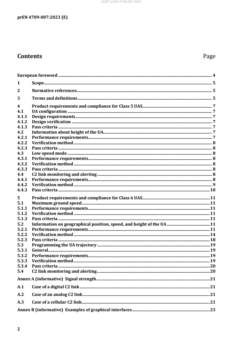
Contents Page
European foreword . 4
1 Scope . 5
2 Normative references . 5
3 Terms and definitions . 5
4 Product requirements and compliance for Class 5 UAS. 7
4.1 UA configuration . 7
4.1.1 Design requirements . 7
4.1.2 Design verification . 7
4.1.3 Pass criteria . 7
4.2 Information about height of the UA . 7
4.2.1 Performance requirements . 7
4.2.2 Verification method . 8
4.2.3 Pass criteria . 8
4.3 Low-speed mode . 8
4.3.1 Performance requirements . 8
4.3.2 Verification method . 8
4.3.3 Pass criteria . 8
4.4 C2 link monitoring and alerting . 8
4.4.1 Performance requirements . 8
4.4.2 Verification method . 9
4.4.3 Pass criteria . 10
5 Product requirements and compliance for Class 6 UAS. 11
5.1 Maximum ground speed . 11
5.1.1 Performance requirements . 11
5.1.2 Verification method . 11
5.1.3 Pass criteria . 11
5.2 Information on geographical position, speed, and height of the UA . 11
5.2.1 Performance requirements . 11
5.2.2 Verification method . 14
5.2.3 Pass criteria . 18
5.3 Programming the UA trajectory . 19
5.3.1 General. 19
5.3.2 Performance requirements . 19
5.3.3 Verification method . 19
5.3.4 Pass criteria . 20
5.4 C2 link monitoring and alerting . 20
Annex A (informative) Signal strength . 21
A.1 Case of a digital C2 link . 21
A.2 Case of an analog C2 link . 21
A.3 Case of a cellular C2 link . 21
Annex B (informative) Examples of graphical interfaces . 23
oSIST prEN 4709-007:2024
prEN 4709-007:2023 (E)
Annex C (informative) Colours and size recommendations for alerts . 26
Annex D (informative) Example of ways to program the UA's trajectory . 29
Annex ZA (informative) Relationship between this document and the essential
requirements of Delegated regulation (EU) 2019/945 of 12 March 2019 on
unmanned aircraft systems and on third-country operators of unmanned aircraft
systems aimed to be covered. 30
Bibliography . 31
oSIST prEN 4709-007:2024
prEN 4709-007:2023 (E)
European foreword
This document (prEN 4709-007:2023) has been prepared by Technical Committee CEN/TC 471 UAS,
the secretariat of which is held by BNAE.
This document is currently submitted to the CEN Enquiry.
This document has been prepared under a standardization request addressed to CEN by the European
Commission. The Standing Committee of the EFTA States subsequently approves these requests for its
Member States.
For the relationship with EU Legislation, see informative Annex ZA, which is an integral part of this
document.
oSIST prEN 4709-007:2024
prEN 4709-007:2023 (E)
1 Scope
This document provides technical specification and verification methods to support compliance with
Commission Delegated Regulation (EU) 2019/945 of 12 March 2019 amended by Commission
Delegated Regulation (EU) 2020/1058 of 27 April 2020 on unmanned aircraft systems and on third-
country operators of unmanned aircraft systems.
This includes compliance with product requirements for UAS intended to be operated under a standard
scenario in the ‘specific’ category (class C5 and class C6 UAS).
This document covers neither UAS intended to be operated in the “Specific” or “Certified” categories of
UAS operations nor UAS lighter than air (e.g. airships and balloons).
Compliance with this document assists in complying with CE marking technical requirements.
This document is only applicable for UA with energy sources based on electro-chemical technologies.
Additional hazards that occur from the characteristics of the payload are excluded and are under the
responsibility of the manufacturer and operator.
The present document covers requirements expressed in Annex, Part 16 requirements (1), (3), (4) and
(6) and Part 17 requirements (1), (3), (6) and (7) of the Regulation 2020/1058.
2 Normative references
The following documents are referred to in the text in such a way that some or all of their content
constitutes requirements of this document. For dated references, only the edition cited applies. For
undated references, the latest edition of the referenced document (including any amendments) applies.
EN 4709-001:—, Aerospace series — Unmanned Aircraft Systems — Part 001: Product requirements and
verification
EN 4709-005:—, Aerospace series — Unmanned Aircraft Systems — Part 005: Verification method for
the Geocaging function
3 Terms and definitions
For the purposes of this document, the terms and definitions given in EN 4709-001 and the following
apply.
ISO and IEC maintain terminology databases for use in standardization at the following addresses:
— ISO Online browsing platform: available at https://www.iso.org/obp/
— IEC Electropedia: available at https://www.electropedia.org/
3.1
alert
indication on the equipment to control the UA remotely meant to attract the attention of and identify to
the remote pilot a non-normal operational or system condition
Note 1 to entry: alerts are classified at levels or categories corresponding to Warning and Caution.
Note 2 to entry: alert indications also include non-normal range markings.
Under preparation. Stage at the time of publication: prEN 4709-001:2021.
Under preparation. Stage at the time of publication: prEN 4709-005:2023.
oSIST prEN 4709-007:2024
prEN 4709-007:2023 (E)
3.2
caution
level or category of alert for conditions that require immediate remote pilot awareness and a less
urgent subsequent remote pilot response than a warning alert
3.3
haptic signal
any type of signal that is transferred to the hand of the user through the handheld equipment to control
the UA remotely in the form of vibrations
3.4
nominal mode
basic modes of operation encountered in normal operation in the absence of any loss of features,
functions or capabilities, or degradation of performance
3.5
warning
level or category of alert for conditions that require immediate remote pilot awareness and immediate
remote pilot response
3.6
orientation reference
reference providing the orientation or direction of a given map with respect to the directions on the
ground or any other reference specified by the manufacturer
EXAMPLE Magnetic north.
3.7
controlled ground area
ground area where the UAS is operated and within which the UAS operator can ensure that only
involved persons are present
3.8
positioning system
system of instrumental and computational components for determining position
EXAMPLES Inertial, integrated, linear, optical and satellite positioning systems
3.9
view
visual content displayed on the graphical interface, which allows the adjustable display of all the
required and supportive visual information by the usage of different windows and zoom levels
3.10
field of view
geographical area that is currently displayed on the view
3.11
total station
electronic tachymeter
tachymeter with microprocessor(s), display and memory for opto-electronic distance measurement,
angle reading, processing, displaying and storing of measurement data
[SOURCE: ISO 9849:2017(en), 3.1.20]
oSIST prEN 4709-007:2024
prEN 4709-007:2023 (E)
3.12
global navigation satellite system
GNSS
system that comprises several networks of satellites that transmit radio signals containing time and
distance data that can be picked up by a receiver, allowing the user to identify the location of the
receiver anywhere around the world
[SOURCE: ISO 7078:2020, 3.1.26]
3.13
GNSS receiver
electronic device that receives and digitally processes signals from GNSS satellites in order to provide
position, velocity and time (of the receiver)
[SOURCE: ISO 7078:2020, 3.5.27]
3.14
clear and concise information
extent to which an information is presented
Note 1 to entry: the information considered in this document is the geographical position (i.e. latitude and
longitude, WGS 84, …) of the UA, its speed and its height above the surface or take-off point according to
Commission Delegated Regulation (EU) 2020/1058 of 27 April 2020 Annex, Part 16 and Part 17.
Note 2 to entry: the attributes considered are visibility, character height, object size, syntax for physical
quantities and units and accuracy.
4 Product requirements and compliance for Class 5 UAS
4.1 UA configuration
4.1.1 Design requirements
Unless the UA is tethered, the UA is not equipped with fixed wings, whether or not equipped with VTOL
capabilities.
4.1.2 Design verification
Unless tethered, verify by visual inspection that the UA is not equipped with fixed wings.
4.1.3 Pass criteria
The UA is not equipped with fixed wings.
4.2 Information about height of the UA
4.2.1 Performance requirements
4.2.1.1 Update rate
Refer to 5.2 for the height of the UA.
4.2.1.2 Height of the UA
Refer to 5.2 for the height of the UA.
oSIST prEN 4709-007:2024
prEN 4709-007:2023 (E)
4.2.2 Verification method
Refer to 5.2 for the height of the UA.
4.2.3 Pass criteria
Compliance with pass criteria, refer to 5.2 for the height of the UA.
4.3 Low-speed mode
4.3.1 Performance requirements
(1) Unless tethered, the UA shall be equipped with a selectable “low-speed mode” limiting the ground
speed to not more than 5 m/s.
(2) The manufacturer shall provide in the manufacturer’s instructions:
a. the procedure how to set the speed, how to select (“activate”) and de-select (“deactivate”) the
“low-speed mode”;
b. conditions and limitations that affect the “Low-speed mode”.
4.3.2 Verification method
— Verify by review of the manufacturers’ instructions that the UA is equipped with a “Low-speed
mode”.
— Determine the maximum horizontal speed of the UA when “Low-speed mode” is selected by any of
the tests described in EN 4709-001:— , 4.2.2.
— Verify that the maximum horizontal speed in all possible flight modes and in any possible direction
of level flight is not exceeded.
— Repeat the selected test 3 times and consider the maximum value measured.
4.3.3 Pass criteria
(1) Compliance with the low-speed mode requirement.
(2) Verify by review of the manufacturer’s instructions that the following is provided:
a. the procedure how to set the speed, how to select (“activate”) and de-select (“deactivate”) the
“low speed mode”;
b. conditions and limitations that affect the “Low-speed mode”.
4.4 C2 link monitoring and alerting
4.4.1 Performance requirements
The UAS shall monitor the command-and-control link and shall provide to the remote pilot:
(1) a visual signal strength indication with at least four levels (strong, medium, weak, loss of C2 link);
(2) a visual caution signal accompanied by an aural and/or haptic alert in case of weak signal strength
indication;
oSIST prEN 4709-007:2024
prEN 4709-007:2023 (E)
(3) a visual warning signal accompanied by an aural and/or haptic alert within a period of time defined
in the manufacturer’s instructions after loss of C2 link. A delay of up to 5 seconds is considered as
an acceptable delay. Otherwise, the manufacturer should provide a risk assessment proving the
safe operation in case of C2 link loss.
(4) (2) and (3) requirements shall be distinguishable;
(5) The signal strength indication shall be based on an index value (or a fusion of several signal
metrics) and appropriate threshold determined by the manufacturer;
NOTE 1 Examples of these values and thresholds for different transmission technologies are given in Annex A.
NOTE 2 For the display of the alert, colours and size recommendations are presented in Annex C.
NOTE 3 For aural, visual and haptic alerts, guidance can be found in EN 61310-1.
NOTE 4 Examples of visual indications:
— warning light at the equipment to control the UA remotely;
— text message on the display of the equipment to control the UA remotely;
— depiction indicating the need for action on the equipment to control the UA remotely.
(6) the manufacturer’s instructions shall include detailed information and specification.
The manufacturer shall define the visual signal strength indication, visual caution signal and visual
warning. Aural and haptic alerts should also be described in the manufacturer’s instructions with
their expected scheme (such as type, frequency, duration and pattern).
4.4.2 Verification method
Carry out the following tests for each of the requirements three times:
(1) visual signal strength indication;
Turn on the UA and the equipment to control the UA remotely and check that the signal strength is
visually provided. Observe the signal strength indication during the tests described in
EN 4709-001:— , 6.7.1 and verify that the indication is continuously provided and reflects a
reduced link quality.
(2) caution signal;
Reduce the signal strength.
NOTE 1 The test can consist of using shielding e.g. entering into building or using a shielded box without
closing to reduce signal strength reception or place UA at the limits of the signal range and move away from
UA with the equipment to control the UA remotely.
(3) warning signal;
Reduce signal strength to loss of connection.
NOTE 2 Perform the test per EN 4709-001:— , 6.7.1.2.1.
(4) characteristics of caution and warning signals;
oSIST prEN 4709-007:2024
prEN 4709-007:2023 (E)
While performing the tests in 4.4.2 (1), (2) and (3), observe and record all visual, aural and haptic
alerts encountered during the test phase.
(5) signal strength measurement;
Perform the following test:
— connect the UA and the equipment to control the UA remotely;
— place the UAS in optimal signal conditions (UA and equipment to control the UA remotely in
close proximity in the case of direct communication) and check the signal quality indicator;
— record signal quality index value and visual signal strength indication on the display;
— gradually reduce signal quality by moving the UA away from the equipment to control the UA
remotely, or by using a signal attenuation system;
— keep recording the signal quality index value and signal strength indication on the display until
the command-and-control link is lost;
— repeat the process three times.
(6) manufacturers’ instructions;
Verify by review of the manufacturer’s instructions that signal strength indication, visual, aural and
or haptic signals are described and specified.
4.4.3 Pass criteria
(1) Visual signal strength indication.
Verify that the signal strength indicated varies from strong signal, medium signal, weaker signal(s)
to no signal reflecting signal strength reduction according to requirement 1 to 3.
(2) Caution signal.
Verify that in case the signal reaches the low value as defined by the manufacturer, a respective
signal is initiated.
(3) Warning signal.
Verify that in case of signal loss, a respective signal is issued within a time frame specified in the
manufacturer’s instructions.
(4) Characteristics of caution and warning signals.
Both signals are distinguishable from each other.
(5) Signal strength measurement.
The visual signal strength indication on the display follows the evolutions of the signal quality index
value as described by the manufacturer. The visual signal strength indication changes at ± 5 % of
the threshold values. If the command-and-control signal is lost, the visual signal strength indication
indicates it.
oSIST prEN 4709-007:2024
prEN 4709-007:2023 (E)
(6) Manufacturer’s instructions.
By review of manufacturer’s instructions, the required information is provided. Aural and haptic
alerts correspond to the alerts described in the manufacturer’s instructions.
5 Product requirements and compliance for Class 6 UAS
5.1 Maximum ground speed
5.1.1 Performance requirements
(1) The manufacturer shall declare the maximum ground speed in level flight in the manufacturer’s
instructions.
(2) The declared maximum speed shall not exceed 50 m/s in level flight.
(3) The maximum speed of the UA shall not exceed the declared maximum ground speed in horizontal
flight in all directions.
5.1.2 Verification method
The verification methodology given in EN 4709-001:— , 4.2.2 shall be applied.
5.1.3 Pass criteria
(1) Verify by review of the manufacturer’s instructions that the maximum ground speed is declared.
(2) Verify that the declared maximum ground speed does not exceed 50 m/s.
(3) Verify that the measured ground speed in level flight does not exceed the declared maximum.
5.2 Information on geographical position, speed, and height of the UA
5.2.1 Performance requirements
5.2.1.1 Update rate
The geographical position of the UA, its speed and its height shall be updated at least every second.
5.2.1.2 Information on geographical position of the UA
5.2.1.2.1 Graphical interface information
The geographical position of the UA shall be shown by a graphical interface included within the
equipment to control the UA remotely. The graphical interface shall allow to display during the flight:
— the geographical position of the UA;
— the position of the take-off point or the position of the remote pilot;
— have a selectable/variable scale;
— provide a map orientation reference and/or any other orientation aid as specified by the
manufacturer.
Where the map is movable on the screen, the geographical interface shall have the possibility to centre
the UA or any other selected item by the remote pilot.
oSIST prEN 4709-007:2024
prEN 4709-007:2023 (E)
All the symbology of items represented on the geographical interface shall be explained in the
manufacturer’s instructions.
Depending on the scale, all elements may not be visible at all times.
NOTE Annex B provides examples of graphical interfaces showing the geographical position of the UA.
The graphical interface shall respect the following requirements:
(1) A geographical map is shown.
(2) The geographical map shows (all of the following):
a. UA location;
b. remote pilot location and/or position of the take-off point (icon);
c. a basemap allowing to locate the drone in its environment. A satellite map is recommended.
However, a map showing only roads, buildings, and other man-made features can be accepted
if it is accurate enough to detect the relative movement of the UA with respect to its
environment;
d. orientation reference and/or any other orientation aid as specified by the manufacturer.
(3) Where a function is provided to manipulate the Field of View (pan, tilt, zoom, centre on location),
the View subject to demonstration is considered appropriate for the intended operation according
to the guidance provided in the manufacturer’s instructions. In addition to such guidance, the view
respects the following requirements:
a. it can be manipulated to display the whole operational volume;
b. it can be manipulated to display both UA, remote pilot and take-off point position; and
c. it can be manipulated to display the UA and the object(s) the UA is intended to interact with.
(4) The UA location is shown as an icon or as a
...