

oSIST prEN 13201-4:2026
(Main)Road lighting - Part 4: Methods of measuring lighting performance
- Abstract
This European Standard specifies measurement conditions and procedures for measuring the photometric quality parameters of road lighting installations, i.e. the quantities that quantify their performances in accordance with EN 13201-2 lighting classes.
Parameters used for quantifying the energy performance of road lighting installations are not considered.
A methodology to evaluate the road lighting performances considering tolerances in the design parameters is described in the informative Annex A.
- Status
- Not Published
- Public Enquiry End Date
- 30-Dec-2026
- Technical Committee
- STV - Steklo, svetloba in razsvetljava v gradbeništvu
- Current Stage
- 4020 - Public enquire (PE) (Adopted Project)
- Start Date
- 30-Sep-2026
- Due Date
- 17-Feb-2027


oSIST prEN 13201-4:2026 is a CEN draft European Standard for road lighting. It specifies the measurement conditions and procedures used to measure the photometric quality parameters of road lighting installations, so users can check performance against the lighting classes in EN 13201-2. It is intended for engineers, laboratories, road authorities, contractors, and maintenance teams that need a common measurement method for testing, monitoring, or investigating road lighting.
What does oSIST prEN 13201-4:2026 specify?
oSIST prEN 13201-4:2026 specifies how to measure the photometric performance of road lighting installations, including the conditions, instruments, grid points, uncertainty treatment, and test reporting needed to make the results comparable. It does not cover parameters used to quantify energy performance.
The document is organized into nine clauses and eight annexes.
| Annex | What it covers |
|---|---|
| A | Important particular parameters and extended uniformity methods |
| B | Normative conventions for symbols of photometric quality parameters |
| C | Guidelines for measurement systems for adaptive road lighting |
| D | Measurements for discrepancies between photometric measures and design expectation |
| E | Measurement uncertainty evaluation |
| F | Practical information for preparing measurement procedures |
| G | Example of report |
| H | Mobile observer concept for luminance measurement with ILMD |
The main clauses cover scope, normative references, terms and definitions, symbols and abbreviations, preliminary information, measurement conditions, photometric measurements, non-photometric parameters, and test reports.
What are the key requirements of oSIST prEN 13201-4:2026?
oSIST prEN 13201-4:2026 requires the measurement procedure to match the measurement aim, the lighting class, and the way the results will be used. In practice, that means the person responsible for the measurement must first decide whether the work is for final testing, lifetime monitoring, adaptive lighting control, or discrepancy investigation, because each case can call for different parameters and geometries.
Measurement planning and comparison of results
Clause 5 states that measurements should be carried out with a detailed operating procedure that includes the standard or design target, uncertainty evaluation, and practical constraints. When results are compared, they should use the same measurement points and, where relevant, the same observer position. For final testing, lifetime monitoring, and compliance checks, this is what makes different campaigns comparable over time.
Static and dynamic systems
Clause 5 allows both static and dynamic measurement systems. The choice depends on the required accuracy, safety, local conditions, and tender requirements. Dynamic systems can cover longer road sections faster, which matters when whole routes or large networks must be assessed.
Instruments, calibration, and uncertainty
Clause 5 requires calibrated instruments with metrological traceability in the range used. Luminance and illuminance meters must be suitable for the specific measurement task, and ILMD use brings extra checks such as shutter repeatability, pixel saturation, ghost images, and optical characteristics.
The standard treats uncertainty as a practical decision tool, not just a calculation exercise. It separates uncertainty from the measuring system, the road lighting installation, and the changing weather or environment. When comparing a result with a requirement, the expanded uncertainty must be taken into account so the comparison is made on the coverage interval, not only on the measured value.
Measurement conditions
Clause 6 requires suitable ageing and stabilization before measurements. Lamps are generally measured after the relevant ageing period, while SSL sources are excluded from that ageing requirement. Measurements must also be taken after the installation has stabilised after switch-on.
Clause 6 also requires the measurement conditions to be suitable for the aim of the work. Climatic conditions, road surface condition, extraneous light, and obstructions can all affect the result and should be controlled, recorded, or both. For luminance measurements in M classes, the road must be dry.
Photometric measurements
Clause 7 requires the nominal grid points and observer positions to follow EN 13201-3. Reduced or alternative grids are allowed only when agreed and documented, and any change in point position must be included in the uncertainty evaluation.
The clause covers:
- luminance measurement, including static and dynamic methods and the mobile observer concept
- horizontal, hemispherical, semicylindrical, and vertical illuminance
- Edge Illuminace Ratio (R_EI)
- threshold increment (f_TI)
These measurements matter because they are the core photometric quantities used to judge road lighting performance. The document also explains when road markings, shadows, or other local effects should be excluded from average and uniformity calculations and recorded instead.
Non-photometric parameters and reporting
Clause 8 covers supporting data such as supply voltage, temperature, humidity, and geometric data like column height, outreach, tilt, orientation, and rotation. These values matter because they help explain why a road performs differently from the design or why results vary between campaigns.
Clause 9 sets out the test report content. The report should state the objective, instruments and calibration, weather and electrical conditions, procedures, uncertainty, results, reasons for any reduced measurement zone, and action taken to deal with extraneous light. For dynamic systems, the report must also include average vehicle speed and the corrections applied.
What terms does oSIST prEN 13201-4:2026 define?
- Automatic measuring system for control purpose - an automatic system that generates a control signal from one or more measured photometric parameters to influence the operating conditions of a road lighting installation.
- Dynamic measurement system - a measurement system that moves along the road surface during measurement.
- Static measurement system - a measurement system that does not move when in service.
- Normative parameter - a quantity defined in EN 13201-2 and calculated according to EN 13201-3, or measured under conditions matching that calculation framework.
- Particular parameter - a quantity calculated, measured, or evaluated under defined conditions that are different from those in EN 13201-3.
- Extended uniformity - a parameter used to analyse the effect of non-homogeneity in the environment or road surface.
- Set measurement - a measurement carried out in an installation to determine the values used by an automatic control system.
- ILMD (imaging luminance measuring device) - a calibrated digital device with a lens and detector matrix used to measure luminance distributions in an image.
Who uses oSIST prEN 13201-4:2026?
oSIST prEN 13201-4:2026 is used by road lighting designers, testing laboratories, inspection teams, road authorities, operators, and maintenance contractors. It is also relevant to buyers and suppliers when measurement methods need to be written into a tender, commissioning plan, acceptance test, maintenance audit, or troubleshooting investigation.
In practice, users apply it to verify compliance with EN 13201-2 lighting classes, check design expectations, monitor degradation over time, assess adaptive lighting control, and investigate discrepancies between measured and expected performance.
What changed in oSIST prEN 13201-4:2026 from the previous edition?
oSIST prEN 13201-4:2026 supersedes EN 13201-4:2015. The foreword states that the former Annex A on tolerances in road lighting installation design has been removed, and that a new Annex H on the mobile observer concept for luminance measurement with ILMD has been added.
Which standards are used with oSIST prEN 13201-4:2026?
| Standard | Contribution |
|---|---|
| EN 12665 | Basic terms and criteria for specifying lighting requirements |
| EN 13032-1 | Measurement and presentation of photometric data of lamps and luminaires; calibration and meter characteristics |
| EN 13201-2 | Road lighting performance requirements and lighting classes |
| prEN 13201-3:2026 | Calculation of performance, grid definition, observer position, and normative photometric parameters |
The document also cites EN 13032-4 for SSL stabilization guidance, EN ISO/IEC 17025 for calibration laboratories, ISO/CIE FDIS 19476 for meter performance, ISO/IEC Guides 98-1, 98-3, 98-4, and 99 for measurement uncertainty and conformity assessment, and CIE 194, CIE 198, and CIE 244 for road lighting measurement practice and ILMD characterization.
What does the oSIST prEN 13201-4:2026 document contain?
oSIST prEN 13201-4:2026 contains the measurement framework for road lighting installations, including choice of method, measurement conditions, grid point location, luminance and illuminance methods, and handling of adaptive lighting and discrepancy investigations. It also contains practical guidance on extraneous light, obstructions, road conditions, and the way measurement results should be compared with requirements.
Several annexes are especially useful in practice. Annex E gives structured uncertainty sources for luminance and illuminance measurements, including dynamic-system effects. Annex G gives a report template that covers geometry, road surface, luminaires, supply, environment, measurement grid, and dynamic-measurement information. Annex H describes how to reconstruct the measurement grid from ILMD images using the mobile observer concept, which is useful for dynamic luminance work and for modern camera-based measurement systems.
Relations
- Effective Date
- 07-Apr-2025
Get Certified
Connect with accredited certification bodies for this standard

Zavod za gradbeništvo Slovenije (ZAG) - Inšpekcija
ZAG inspection body for construction products, structures, and materials.
Sponsored listings
Frequently Asked Questions
oSIST prEN 13201-4:2026 is a draft published by the Slovenian Institute for Standardization (SIST). Its full title is "Road lighting - Part 4: Methods of measuring lighting performance". This standard covers: This European Standard specifies measurement conditions and procedures for measuring the photometric quality parameters of road lighting installations, i.e. the quantities that quantify their performances in accordance with EN 13201-2 lighting classes. Parameters used for quantifying the energy performance of road lighting installations are not considered. A methodology to evaluate the road lighting performances considering tolerances in the design parameters is described in the informative Annex A.
This European Standard specifies measurement conditions and procedures for measuring the photometric quality parameters of road lighting installations, i.e. the quantities that quantify their performances in accordance with EN 13201-2 lighting classes. Parameters used for quantifying the energy performance of road lighting installations are not considered. A methodology to evaluate the road lighting performances considering tolerances in the design parameters is described in the informative Annex A.
oSIST prEN 13201-4:2026 is classified under the following ICS (International Classification for Standards) categories: 93.080.40 - Street lighting and related equipment. The ICS classification helps identify the subject area and facilitates finding related standards.
oSIST prEN 13201-4:2026 has the following relationships with other standards: It is inter standard links to SIST EN 13201-4:2016. Understanding these relationships helps ensure you are using the most current and applicable version of the standard.
oSIST prEN 13201-4:2026 is available in PDF format for immediate download after purchase. The document can be added to your cart and obtained through the secure checkout process. Digital delivery ensures instant access to the complete standard document.
Standards Content (Sample)
SLOVENSKI STANDARD
01-november-2026
Cestna razsvetljava - 4. del: Metode merjenja svetlobne učinkovitosti
Road lighting - Part 4: Methods of measuring lighting performance
Straßenbeleuchtung - Teil 4: Methoden zur Messung der Gütemerkmale von
Straßenbeleuchtungsanlagen
Éclairage public - Partie 4 : Méthodes de mesure des performances photométriques
Ta slovenski standard je istoveten z: prEN 13201-4
ICS:
93.080.40 Cestna razsvetljava in Street lighting and related
pripadajoča oprema equipment
2003-01.Slovenski inštitut za standardizacijo. Razmnoževanje celote ali delov tega standarda ni dovoljeno.
DRAFT
EUROPEAN STANDARD
NORME EUROPÉENNE
EUROPÄISCHE NORM
November 2026
ICS Will supersede EN 13201-4:2015
English Version
Road lighting - Part 4: Methods of measuring lighting
performance
Éclairage public - Partie 4 : Méthodes de mesure des Straßenbeleuchtung - Teil 4: Methoden zur Messung
performances photométriques der Gütemerkmale von Straßenbeleuchtungsanlagen
This draft European Standard is submitted to CEN members for enquiry. It has been drawn up by the Technical Committee
CEN/TC 169.
If this draft becomes a European Standard, CEN members are bound to comply with the CEN/CENELEC Internal Regulations
which stipulate the conditions for giving this European Standard the status of a national standard without any alteration.
This draft European Standard was established by CEN in three official versions (English, French, German). A version in any other
language made by translation under the responsibility of a CEN member into its own language and notified to the CEN-CENELEC
Management Centre has the same status as the official versions.
CEN members are the national standards bodies of Austria, Belgium, Bulgaria, Croatia, Cyprus, Czech Republic, Denmark, Estonia,
Finland, France, Germany, Greece, Hungary, Iceland, Ireland, Italy, Latvia, Lithuania, Luxembourg, Malta, Netherlands, Norway,
Poland, Portugal, Republic of North Macedonia, Romania, Serbia, Slovakia, Slovenia, Spain, Sweden, Switzerland, Türkiye and
United Kingdom.
Recipients of this draft are invited to submit, with their comments, notification of any relevant patent rights of which they are
aware and to provide supporting documentation.
Warning : This document is not a European Standard. It is distributed for review and comments. It is subject to change without
notice and shall not be referred to as a European Standard.
EUROPEAN COMMITTEE FOR STANDARDIZATION
COMITÉ EUROPÉEN DE NORMALISATION
EUROPÄISCHES KOMITEE FÜR NORMUNG
CEN-CENELEC Management Centre: Rue de la Science 23, B-1040 Brussels
© 2026 CEN All rights of exploitation in any form and by any means reserved Ref. No. prEN 13201-4:2026 E
worldwide for CEN national Members.
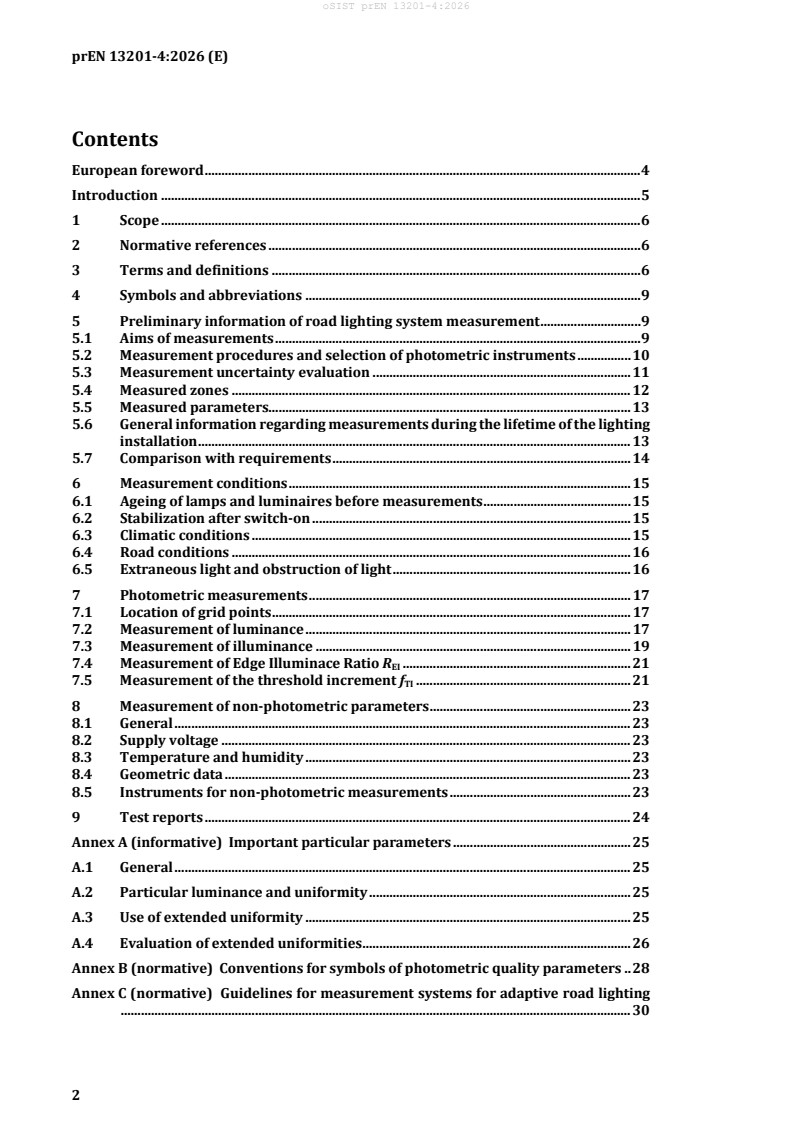
Contents
European foreword . 4
Introduction . 5
1 Scope . 6
2 Normative references . 6
3 Terms and definitions . 6
4 Symbols and abbreviations . 9
5 Preliminary information of road lighting system measurement . 9
5.1 Aims of measurements . 9
5.2 Measurement procedures and selection of photometric instruments . 10
5.3 Measurement uncertainty evaluation . 11
5.4 Measured zones . 12
5.5 Measured parameters. 13
5.6 General information regarding measurements during the lifetime of the lighting
installation . 13
5.7 Comparison with requirements . 14
6 Measurement conditions . 15
6.1 Ageing of lamps and luminaires before measurements . 15
6.2 Stabilization after switch-on . 15
6.3 Climatic conditions . 15
6.4 Road conditions . 16
6.5 Extraneous light and obstruction of light . 16
7 Photometric measurements . 17
7.1 Location of grid points . 17
7.2 Measurement of luminance . 17
7.3 Measurement of illuminance . 19
7.4 Measurement of Edge Illuminace Ratio R . 21
EI
7.5 Measurement of the threshold increment f . 21
TI
8 Measurement of non-photometric parameters . 23
8.1 General . 23
8.2 Supply voltage . 23
8.3 Temperature and humidity . 23
8.4 Geometric data . 23
8.5 Instruments for non-photometric measurements . 23
9 Test reports . 24
Annex A (informative) Important particular parameters . 25
A.1 General . 25
A.2 Particular luminance and uniformity . 25
A.3 Use of extended uniformity . 25
A.4 Evaluation of extended uniformities . 26
Annex B (normative) Conventions for symbols of photometric quality parameters . 28
Annex C (normative) Guidelines for measurement systems for adaptive road lighting
........................................................................................................................................................ 30
Annex D (informative) Measurements for investigation of discrepancies between
photometric measures and design expectation . 32
)
Annex E (informative) Measurement uncertainty evaluation . 33
E.1 Luminance measurements . 33
E.2 Illuminance measurements . 37
Annex F (informative) Practical information . 41
F.1 General . 41
F.2 Measurement precautions . 41
F.3 Measurement organization . 41
Annex G (informative) Example of report . 42
G.1 Premise . 42
G.2 General test information . 42
G.3 Geometrical data . 42
G.4 Road surface data . 42
G.5 Lamp and luminaire data . 42
G.6 Electricity supply . 43
G.7 Environmental conditions . 43
G.8 Condition of installation . 44
G.9 Measuring devices data. 44
G.10 Photometric measuring devices characteristics . 44
G.11 Measurement grid . 45
G.12 Light monitoring record . 45
G.13 Specific information for dynamic measurements . 46
Annex H (informative) Guidelines for the use of the mobile observer concept for
luminance measurement with ILMD . 47
H.1 Motivation . 47
H.2 Measurement methodology with an angle of observation from the horizontal α
........................................................................................................................................................ 47
H.3 Methodology of measurements with an observation angle different from 1° from
the horizontal. . 49
Bibliography . 50
European foreword
This document (prEN 13201-4:2026) has been prepared by Technical Committee CEN/TC 169
“Light and lighting”, the secretariat of which is held by DIN.
This document is currently submitted to the enquiry.
This document will supersede EN 13201-4:2015.
The main technical changes in this document are:
— Former Annex A – Evaluation of to tolerances in road lighting installation design has been
removed.
— A new Annex H – Guidelines for the use of the mobile observer concept for luminance
measurement with imaging luminance measuring devices (ILMD) has been added.
Introduction
The purpose of this document is to:
a) establish conventions and procedures for the characterization based on measurements of road
lighting installations considering the photometric quality parameters, i.e. the set of quantities
that characterize a lighting class, specified in EN 13201-2;
b) give advice on the use and selection of luminance meters and illuminance meters for this
particular application;
c) specify measurement requirements according to the aims of the measurement and expected
accuracy;
d) establish conventions for evaluating the measurement uncertainty of involved parameters;
e) give information on the application of tolerance analysis in the design of the lighting
installation.
A non-exhaustive list of possible measurement aims is:
f) verification of compliance with standard requirements;
g) verification of compliance with design expectations;
h) road lighting installation monitoring, e.g. for maintenance purposes;
i) road lighting installation control, e.g. for optimizing energy saving;
j) investigation of discrepancies between real lighting conditions and design expectations.
The conventions for observer position and location of measurement points are those adopted in
EN 13201-3. However, relaxation from these is permitted especially where the measurements are
used for monitoring the performance of a road lighting installation, to control its performances or
other purposes or when different conditions are specified in the road lighting installation design.
Conditions, which can lead to inaccuracies, are identified and precautions are given to minimize
and quantify these.
This document is intended to be used for writing measurement procedures for the characterization
of road lighting installations.
Criteria for deciding when measurements should be done, on the purpose of measurements and on
how the measurement results shall be used fall outside the scope of this document.
1 Scope
This document specifies measurement conditions and procedures for measuring the photometric
quality parameters of road lighting installations, i.e. the quantities that quantify their performances
in accordance with EN 13201-2 lighting classes.
Parameters used for quantifying the energy performance of road lighting installations are not
considered.
2 Normative references
The following documents, in whole or in part, are normatively referenced in this document and are
indispensable for its application. For dated references, only the edition cited applies. For undated
references, the latest edition of the referenced document (including any amendments) applies.
EN 12665, Light and lighting - Basic terms and criteria for specifying lighting requirements
EN 13032-1, Light and lighting − Measurement and presentation of photometric data of lamps and
luminaires − Part 1: Measurement and file format
EN 13201-2, Road lighting - Part 2: Performance requirements
prEN 13201-3:2026, Road lighting − Part 3: Calculation of performance
3 Terms and definitions
For the purposes of this document, the terms and definitions given in EN 12665 and the following
apply.
ISO and IEC maintain terminological databases for use in standardization at the following
addresses:
• IEC Electropedia: available at http://www.electropedia.org/
• ISO Online browsing platform: available at https://www.iso.org/obp/ui/#home
3.1
automatic measuring system for control purpose
automatic system used to generate a control signal, correlated to one or more measured
photometric parameters that can influence the operating conditions of a road lighting installation
Note 1 to entry: Metrological parameters, such as measurement repeatability and stability, generally are the
main characteristic of the system.
3.2
dynamic measurement system
measurement system that moves along the road surface to carry out the measurement
3.3
static measurement system
measurement system that does not move when in service
3.4
normative parameter
quantity defined in EN 13201-2 following calculation rules of EN 13201-3
Note 1 to entry: The value of the parameter can:
a) give standard requirements;
b) give values effectively required by the road authority (design expectations). These values can
differ from values given in EN 13201-2;
c) be evaluated using the appropriate algorithm (based on a physical model of light propagation in
the environment) as specified by EN 13201-3;
d) be measured following conditions that fit those specified in EN 13201-3 for the points of the grid
and, if necessary, for the position of the observer and verifying if the influence of the metrological
characteristics of the measuring instrument is compatible with the physical definition of the parameter.
3.5
particular parameter
quantity calculated, measured or evaluated in accordance with given and well-defined conditions,
but different to those specified in EN 13201-3
Note 1 to entry: The set of conditions shall be described with the measurement results.
3.6
normative luminance
L
luminance of an elementary surface centred at a given point when viewed from the standard
observation position according to EN 13201-3
Note 1 to entry: The normative luminance is expressed in candela per square metre.
3.7
particular luminance
L
p
luminance of a surface centred at a given point when viewed from a specified observation position
and/or specified conditions highlighted using the subscript p
Note 1 to entry: The particular luminance is expressed in candela per square metre.
3.8
extended uniformity
particular parameter introduced to mathematically analyse the influence of non-homogeneity of
the environment or of the road surface
Note 1 to entry: This is particularly useful when dynamic measurement systems are used and the presence
of non- homogeneity cannot be evaluated before the measurement.
Note 2 to entry: Extended uniformity is discussed in the informative Annex A.
3.9
set measurement
measurement carried out in an installation to determine the values of parameters used by an
automatic measuring system for control purpose
3.10
imagine luminance measuring device
ILMD
digital electronic device, equipped with a lens, an adequate photometric matching filter, a sensor
made by a matrix of detector (pixel), and calibrated for measuring the luminance distributions of
the framed scene
Note 1 to entry: Every pixel is calibrated to determine the luminance values of the space imaged on its
surface by the lens system.
Note 2 to entry: The matrix of pixel is generally realized with CCD (charge coupled device) or CMOS
(complementary metal oxide semiconductor) sensors.
Note 3 to entry: In literature different terms can be found to describe ILMD such as multi-channel luminance
meter, luminance mapper, array (or matrix) luminance meter, video photometer, photo luminance meter,
CCD luminance meter, luminance camera, multidirectional luminance meter, spatial luminance profile
device.
[SOURCE: EN 12665:2024, 3.6.9]
3.11
split detector system
method of measuring horizontal illuminance using two detectors, the first detector of every couple
measures light from the hemisphere in the forward direction, the second one measures light from
the hemisphere in the rearward direction
Note 1 to entry: This method is usually applied in dynamic measurement system where one detector is
mounted on the front of the vehicle and the other on the rear of the vehicle.
Note 2 to entry: The point illuminance value is obtained by summing the readings of the two detectors at the
same spatial point.
3.12
adaptive lighting
lighting responding to circumstances or according to predefined conditions, while maintaining the
lighting quality within the specified requirements for these circumstances or conditions
Note 1 to entry: The requirements can focus on different aspects such as energy efficiency, dynamic user
needs, visual task or ambience.
Note 2 to entry: The terms “smart lighting” and “intelligent lighting” are sometimes used with a similar
meaning.
Note 3 to entry: When applied to road lighting this includes temporal changes in relation to traffic volume,
time and weather.
[SOURCE: EN 12665:2024, 3.2.71]
4 Symbols and abbreviations
EN 13201-3 lists the normative photometric quality parameters of a road lighting installation.
For particular measurement purposes, in addition of normative parameters, a set of particular
parameters is described in the informative Annex A. In accordance with the measurement aims and
measurement procedures, the person responsible for the measurement decides if it is necessary to
use these parameters.
When necessary, to clearly specify with a symbol the meaning or the measurement conditions
linked to a parameter the conventions described in the normative Annex B shall be adopted.
5 Preliminary information of road lighting system measurement
5.1 Aims of measurements
At least four different aims require the measurement of the photometric quality parameters of a
road lighting system:
Measurements at the final testing phase: measurements carried out during the final
testing/commissioning phase of the road lighting installation, to verify the compliance with
standard requirements and/or with design expectations. These results can be used for the road
lighting installations formal approval.
Measurements during the road lighting lifetime: measurements carried out at pre-determined
intervals during the road lighting lifetime, to quantify the degradation of the lighting performance
and to define the need for maintenance or to verify the compliance of the road lighting installation
with the standard requirements or design expectations, generally based on maintained values.
Measurements for adaptive road lighting: measurements may be carried out continuously or at
pre-determined intervals to control the luminous flux of luminaires in adaptive road lighting,
where the installations performance is kept at the given value within a given tolerance. Where
possible, measurements should be carried out with the lighting system configured in ways that are
representative of actual use. A schedule of system settings at which performance will be measured
should be agreed with all parties.
Measurements for investigation of discrepancies: measurements carried out as and when required
to investigate discrepancies between measures and design expectations or environment influence.
For every aim different measurement procedures, requirements and metrological characteristics
of instruments shall be considered.
The main part of this document considers requirements for measurement at the final testing phase
and during the road lighting lifetime. Peculiarities or additional requirements for measurements
for adaptive road lighting are given in the normative Annex C and for investigation of discrepancies
in the informative Annex D.
The set measurement (see 3.9) is considered as a peculiar measurement that shall follow
requirements for measurement at the final testing phase.
Except for the set measurement, when measurement results need to be compared they shall be
carried out considering the same set of measurement points and, if required, observer position.
Measurements shall be carried out following a detailed operating procedure that shall consider the
standard requirements or design expectations, describes the evaluation of measurement
uncertainty (see informative guidelines in Annex E), specifies the conditions of its applicability and
considers practical aspects (see informative guidelines in Annex F).
The objectives of the measurement shall be written in the test report (see Clause 9 and the
informative Annex G).
5.2 Measurement procedures and selection of photometric instruments
5.2.1 Static versus Dynamic measurements
Measurements can be done with either static or dynamic measurement systems. For a given
measurement aim (see 5.1), the selection of the adopted system shall be done considering the
required accuracy of the results and other constrains that can rise from safety reasons, local and
temporary conditions and/or tender requirements.
A dynamic measurement system can measure the total length (or surface) of a road lighting
installation in a more reasonable time than a static measurement system. This peculiarity can be
useful when the homogeneity of performances of the road lighting installation shall be investigated
or when an entire road network has to be evaluated at a given instant.
NOTE Guidance on design and use of dynamic measurement systems is given in CIE 194:2011.
5.2.2 General requirements on measurement procedures and on measurement devices
The measurement procedures adopted shall be suited to the purpose of the measurements.
For a given measurement aim, the maximum acceptable value of the expanded measurements
uncertainly shall be defined considering national or tender requirements and upon the evaluation
of the influence this uncertainty can have on the decision taken using the measurement results or
on the power consumption of the road lighting installation or any other parameters defined in
EN 13201-5.
All instruments shall be calibrated in the range used to ensure their metrological traceability.
NOTE 1 Calibration performed by an EN ISO/IEC 17025 accredited calibration laboratory guaranties this
requirement.
The metrological characteristics of the instruments used shall be suited to the purpose of the
measurements. Luminance shall be measured with a luminance meter which has a performance
suitable for the purpose of the measurements. Illuminance shall be measured with an illuminance
meter which has a performance suitable for the purpose of the measurements:
• for the measurement of horizontal and vertical illuminance a photometer head for the
measurement of planar illuminance is required;
• for semicylindrical or hemispherical illuminance a photometer head designed for this purpose
is required.
The instruments metrological performances shall be evaluated for the specific conditions of the
application.
Therefore, if needed, the calibration and photometric characteristics of the detector used shall be
corrected taking account of the ambient temperature and humidity conditions during
measurements and the spectra emitted in the visible region by the luminaires.
Instruments used for measurement of photometric parameters shall be characterized in
accordance with EN 13032 1 for all the relevant parameters and their influence shall be considered
in the uncertainty evaluation model.
NOTE 2 Guidance on the performance of illuminance and luminance meters is given in ISO/CIE
FDIS 19476.
5.2.3 Specific requirements for luminance meter
For every type of luminance meter the influence of light sources external to the framed field shall
be considered.
For every type of luminance meter, in every case of grid point measurement the angular subtense
of the measured road surface shall not be greater than 2 min of arc in the vertical plane and not
greater than 20 min of arc in the horizontal plane. The minimum angular subtense shall be no lower
of 1 min of arc.
NOTE 1 The field of calculation specified in EN 13201-3 commences 60 m from the observer. This means
that to prevent overlap of the measurement areas as seen through a luminance meter set at this distance, the
maximum value of angle of the measurement cone has the value indicated above.
NOTE 2 The minimum value of the angular subtense consider a conventional visual acuity of 1 min of arc.
If the measurement is carried out at a closer distance respect to the nominal positions of the
observer given in EN 13201-3 (see 7.2.1) it is recommended that the measurement cone of the
luminance meter should not exceed 30 min of arc.
The size of measurement area on the road should not exceed 10 % of the lane width in the
transversal direction, nor 50 % of the distance between calculation points in the longitudinal
direction as defined in EN 13201-3, but the size of the measurement area on the road should not
be greater than 0,5 m transversely and 2,5 m longitudinally.
5.2.4 Additional requirements for ILMD
For ILMDs the influence of shutter repeatability, pixel saturation and ghost images shall also be
considered. See CIE 224.
If an ILMD is used the luminance for each grid point may be determined by averaging the reading
of adjacent pixels. In every case the conditions on the angular subtense of the measured surfaces
shall comply with requirements given in 5.2.3.
5.3 Measurement uncertainty evaluation
The measurement uncertainty can be considered as having three groups of components:
1. Those concerning the metrological characteristics of the measurement system and the
influence of measurement procedures;
2. Those concerning the influence of the nominal characteristics and layout of the road lighting
installation being measured;
3. Those concerning the influence of the instantaneous characteristics of the road lighting
installation being measured, and of the weather and environmental conditions.
These three groups shall be separated because the last one can change significantly from one
measurement to another, while the influence of the measurement system can remain substantially
constant.
The various sources of measurement uncertainty can be classified as:
— accuracy of measurement instruments;
— accuracy of the coordinate reference of the measured point or area (if relevant);
— influence of the measurement procedure;
— influence of data elaboration methods;
— road lighting installation characteristics and stability of the photometric parameter’s during
measurement;
— electrical power supply conditions;
— weather conditions (temperature, relative humidity, wind velocity, etc.);
— environmental conditions (presence of trees, shielding objects, disturbing light sources, other
lighting installations, etc.).
For practical reasons this document does not require the evaluation of the uncertainty contribution
of the last three, but only a description in the test report of their conditions, because:
— they are not usually under the control of the measurement team;
— their evaluation or measurement can be difficult or expensive;
— the road lighting installation should normally be evaluated in real working conditions that do
not need to be quantitatively known in detail;
— the influence of these matters on the measured illuminance or luminance value is generally not
known, and it is likely to be impossible to determine without a laborious and expensive set of
measurements.
If point values or uniformities are given in the test report, the influence of the detector
misalignment (e.g. the detector surface is not in the nominal position with respect to grid points)
for illuminance measurements or position and dimensions of the framed surface for luminance
measurements shall be considered when evaluating measurement uncertainties. This correlation
is a characteristic of the road lighting installation (spatial variation of illuminance or luminance
near the point due to non-uniform light distribution) and not of the measurement system or
measurement procedures.
This contribution to the measurement uncertainties need not be considered for average values.
Guidelines for the evaluation of measurement uncertainty in road lighting installation
characterization are given in the informative Annex E.
NOTE Guidance on the calculation of measurement uncertainty is given in ISO/IEC Guide 98-1:2024 and
ISO/IEC Guide 98-3:2008, there is also guidance related to photometric measurement in CIE 198.
5.4 Measured zones
The measurements shall consider the entire length of the road lighting installation and all its
operating conditions (lighting classes).
If the road lighting installation characteristics are designed as constant for the total length of the
installation, it is possible to select a relevant number of zones and to carry out measurements only
in these zones (measured zones). In this case a description of the reasons, justifications and
consequences of this choice shall be written in the test report.
NOTE If the luminous flux emitted by luminaires is strictly correlated to their supply voltage, a possible
reason for selecting particular measurement zones is the voltage drop in the power supply line.
5.5 Measured parameters
The road geometrical parameters in the measured zone (column spacing, carriage and lane width)
shall be measured or known to allow for defining the reference for point coordinates and the
nominal values of point coordinates.
The position, inclination and orientation of the sensitive surface of the illuminance meter (for
illuminance measurement) or of the position of measured surface (for luminance measurement)
with respect to the nominal grid points shall be recorded in the test report.
For illuminance measurement the z coordinate (height of the light sensitive surface of the detector
with respect to the road surface) shall also be specified.
NOTE These parameters are specified using their nominal value and tolerances, or the measured values
with uncertainty.
Measurement for the verification of compliance with standard requirements shall consider all the
photometric quality parameters for the pertinent lighting class/classes.
A reduced set of parameters may be adopted if agreed with the purchaser or operator and if this
choice is described in the road installation design.
Measurement for the verification of compliance with design expectation shall consider a congruent
set of parameters as specified and evaluated in the road lighting installation design.
EXAMPLE This set can specify the measurement of illuminance in grid points instead of the road surface
average luminance and the calculation of uniformities considering these values.
The following additional points shall be described in the test report:
a) electrical power supply conditions,
b) weather and environmental conditions,
and shall be measured if requested as part of a tender specification or required as part of a
pertinent standard (see Clause 8).
If a installation specification or pertinent standard require the measurement of illuminance, as a
preliminary verification step for M lighting classes, point illuminances at the same points of the grid
used for luminance calculation shall be calculated for M lighting classes and illuminance measured
at the same points.
If M lighting classes (see EN 13201-2) are considered and the project has allows a tolerance this
should restrict the verification of compliance with standard requirements to the illuminance
verifications only.
5.6 General information regarding measurements during the lifetime of the
lighting installation
Measurements during the road lighting lifetime are usually carried out before or after installation
maintenance, in accordance with design requirements.
A limited set of measured parameters and simplified measurement geometry may be selected in
accordance with the design specifications or tender requirements.
The determination of some parameters can even be avoided, such as the verifications of the
electrical working conditions of the installation, unless requested as part of a tender specification
or required as part of a pertinent standard.
If measurements are carried out at pre-determined intervals or periodically to quantify the
degradation of the lighting performance they may be done using simplified procedures. Different
set of parameters or geometries may be measured but at least one parameter with a given geometry
shall be measured for comparison purpose each time measurements are taken.
Correlation between the parameters measured in these conditions and the normative parameters
shall consider previous measurements or specific measurement conditions describe in the road
lighting installation design. However, all measurements shall be carried out in a compatible way
each time monitoring is carried out.
5.7 Comparison with requirements
All comparison of measured results with standard requirements or design expectations shall be
carried out considering the expanded measurement uncertainty of the measure:
a) for parameters that require a value greater or equal to a given level, the lower limit of the
coverage interval of the expanded measurement uncertainty shall be greater or equal to the
given level;
b) for parameters that require a value lower or equal to a given level, the upper limit of the
coverage interval of the expanded measurement interval shall be lower or equal to the given
level.
NOTE 1 The expanded measurement uncertainty is defined in ISO/IEC Guide 99:2007, definition 2.35.
NOTE 2 The coverage interval is defined in ISO/IEC Guide 99:2007, definition 2.36.
NOTE 3 Guidance on the role of measurement uncertainty in conformity assessment is given in
ISO/IEC Guide 98-4.
This standard does not give requirements for the range of acceptable values of measurement
uncertainty.
The expanded measurement uncertainty required for measurements can be indicated at the final
engineering stage as requirements for optimization of management or electrical energy
consumptions.
For the verification of compliance with standard requirements the measured values shall be
compared to the specific road lighting installation parameters. Generally, the requirement of
EN 13201-2 shall be used.
For the verification of compliance with design expectation the measured values shall be compared
to the congruent set of parameters specified and evaluated in the road lighting installation design.
If specific design parameters are given in the tender they shall be used.
In the declaration of compliance with standard requirements all the parameters that identify a
given lighting class shall be mentioned. Non-conformities require the measurement of other
photometric or not-photometric parameters in the installation, if the reasons of the discrepancies
are to be investigated (see informative Annex D).
6 Measurement conditions
6.1 Ageing of lamps and luminaires before measurements
Generally, measurements shall be carried out after a period of ageing of the light sources installed
in luminaires of not less than the period specified, for a given lamp type, in EN 13032-1.
No ageing is required for Solid State Light (SSL) sources.
6.2 Stabilization after switch-on
Luminaires require a period of time for their light output to stabilize, and all measurements shall
be done after this stabilization period.
NOTE 1 Guidance on the stabilization period for different lamp typologies is given in EN 13032-1.
NOTE 2 Guidance on the stabilization period for SSL light sources is given in EN 13032-4.
Monitoring readings shall be taken if there are concerns about the stability of the road lighting
installation during the period of measurement.
EXAMPLE Illuminance measurements at the same location or locations should be taken at regular time
intervals to ensure that stability has been reached and maintained before and during the period of definitive
light measurements of the road lighting installation.
NOTE 3 Depending on the type of lamps and road lighting installation adequate information is obtained
by monitoring the supply voltage.
6.3 Climatic conditions
6.3.1 General
The climatic conditions should be such as not to affect measures significantly, unless this is
intended to.
NOTE In some weather conditions, atmospheric absorption significantly reduces the illuminance level
or modifies the luminance measured.
If the climatic conditions at the measurement time do not represent the conditions required for the
measurement aim, the person responsible for the measurement should decide whether to
postpone the measurements.
6.3.2 Instruments
High or low temperatures can affect the calibration and the accuracy of the light measuring
instruments.
Condensation or moisture on light transmitting surfaces of measuring instruments or on their
electric circuits can affect their accuracy.
High wind speeds can make the measuring instruments vibrate or oscillate.
The influence of climatic conditions on the instrument performances shall be considered using
correction factors. These uncertainties shall be considered in the measurement uncertainty
evaluation.
If the climatic conditions are outside the range of the known correction factors the person
responsible for the measurement shall postpone the measurements.
6.3.3 Road lighting installations
High or low temperatures or high wind speeds can affect the light output of thermally sensitive
lamps or luminaires.
High wind speeds can make the luminaires oscillate.
The light transmission of the atmosphere affects the light reaching the surface to be measured, and
in the case of luminance measurements the light reaching the luminance meter from the surface to
be measured.
The climatic conditions should be such as not to affect the measurements significantly, unless this
is intended.
Luminance measurements shall only be performed when the road is dry when considering the M
Classes requirements for dry conditions.
NOTE When taking dry surface measurements even a slight dampness of the road surface significantly
affects the luminance of the road surface.
If the climatic conditions at the measurement time do not represent the conditions evaluated in the
design phase of the road lighting installation, the person responsible for the measurement should
decide whether to postpone the measurements.
6.4 Road conditions
The photometric characteristics of the road surface can largely evolve over time, especially during
the first three years of age of the material.
In case of luminance measurements on a new road surface, measured values can be different from
the expected ones because the actual reduced luminance coefficient is different from that used at
the design stage (measured or obtained from standard road surface tables).
In this case road surface conditions can be estimated comparing illuminance measurements and
illuminance calculation (see informative Annex E).
6.5 Extraneous light and obstruction of light
When measurements are intended to record the lightin
...