

kSIST FprEN IEC 61076-2-118:2026
(Main)Circular connectors - Detail specification for shielded and unshielded, free and fixed connectors with bayonet-locking size b12, b17, b23 and b40, for power, signal and data transmission
General Information
- Abstract
- Status
- Not Published
- Public Enquiry End Date
- 26-Dec-2024
- Technical Committee
- I11 - Imaginarni 11
- Current Stage
- 5020 - Formal vote (FV) (Adopted Project)
- Start Date
- 27-Jan-2026
- Due Date
- 17-Mar-2026
- Completion Date
- 29-Jan-2026

Overview
kSIST FprEN IEC 61076-2-118:2026 defines detailed requirements for circular connectors used in electrical and electronic equipment, specifically focusing on shielded and unshielded, free and fixed connectors with bayonet-locking in sizes B12, B17, B23, and B40. Developed by CLC in conjunction with the IEC, this standard provides guidance on connectors capable of transmitting power, signal, and data across various industrial applications. It covers the performance, dimensional requirements, safety aspects, and variant combinations of these versatile connector systems, ensuring reliability and compatibility in demanding environments.
Key Topics
Connector Sizes and Types: This standard specifies four size variants (B12, B17, B23, B40) and details both shielded and unshielded, free and fixed connector options. Connectors are available as rewirable or non-rewirable and can be either straight or angled.
Bayonet-Locking Mechanism: The featured bayonet-locking ensures secure mating and unmating, providing robust vibration resistance and protection against accidental disconnection, which is essential for industrial and high-reliability applications.
Contact Configurations:
- Power contacts (currents up to 64 A, voltages up to 600 V)
- Signal contacts (up to 20 A, 50 V AC/DC)
- Data contacts (up to 8 A, data transmission up to 600 MHz)
Climatic and Mechanical Classification: Specifications include performance in various temperature and vibration conditions, ensuring usability in industrial environments.
Type Designation: Unique identification based on size, contact configuration (power, signal, data), and application type. Codings ensure correct mating and prevent improper connections.
Safety Compliance: References IEC 61984 for safety aspects, especially for extra-low voltage (ELV) applications and connectors incorporating protective earthing (PE).
Applications
kSIST FprEN IEC 61076-2-118:2026 is highly relevant for sectors requiring robust, reliable, and secure electrical connectivity under harsh conditions. Typical applications include:
- Industrial Automation: Machinery and production line interconnects where quick connection/disconnection, resistance to vibration, and secure locking are critical.
- Power and Data Distribution: Systems where power, control signals, and data must be transmitted simultaneously using a compact and standardized interface.
- Transportation and Rail: In vehicles or rolling stock where connectors face mechanical shocks, vibrations, and climatic extremes.
- Process Control and Instrumentation: Where sensor modules and controllers require shielded, interference-resistant linkages.
- Renewable Energy: Wind, solar, and other generator connections where modular plug-and-play wiring is necessary.
The clear identification system and diverse configurations make these connectors suitable for both new designs and upgrades of existing equipment, supporting power over data as well as pure data transmission paths.
Related Standards
When implementing or specifying circular connectors according to kSIST FprEN IEC 61076-2-118:2026, consider the following relevant standards for complete compliance and compatibility:
- IEC 61076-1: Generic specification for connectors for electronic equipment.
- IEC 61984: Safety requirements and tests for connectors.
- IEC 60050-581, IEC 60068-1: Electrotechnical vocabulary and general environmental testing guidance.
- IEC 60352 (series): Solderless connection methods, such as crimped, insulation displacement, or press-in.
- IEC 60512 (series): Test and measurement procedures for connector electrical and mechanical properties.
- IEC 60529: Degrees of protection provided by enclosures (IP Code).
- IEC 60664-1: Insulation coordination for low-voltage equipment.
By adhering to these standards alongside FprEN IEC 61076-2-118, manufacturers and users ensure international compatibility, safety, and high performance for circular connector solutions in demanding environments.
Keywords: circular connectors, bayonet locking, shielded connectors, unshielded connectors, power transmission, signal transmission, data transmission, industrial connectors, connector standards, IEC 61076-2-118, connector specifications, electrical connectors.
Frequently Asked Questions
kSIST FprEN IEC 61076-2-118:2026 is a draft published by the Slovenian Institute for Standardization (SIST). Its full title is "Circular connectors - Detail specification for shielded and unshielded, free and fixed connectors with bayonet-locking size b12, b17, b23 and b40, for power, signal and data transmission". This standard covers: Circular connectors - Detail specification for shielded and unshielded, free and fixed connectors with bayonet-locking size b12, b17, b23 and b40, for power, signal and data transmission
Circular connectors - Detail specification for shielded and unshielded, free and fixed connectors with bayonet-locking size b12, b17, b23 and b40, for power, signal and data transmission
kSIST FprEN IEC 61076-2-118:2026 is classified under the following ICS (International Classification for Standards) categories: 31.220.10 - Plug-and-socket devices. Connectors. The ICS classification helps identify the subject area and facilitates finding related standards.
kSIST FprEN IEC 61076-2-118:2026 is available in PDF format for immediate download after purchase. The document can be added to your cart and obtained through the secure checkout process. Digital delivery ensures instant access to the complete standard document.
Standards Content (Sample)
SLOVENSKI STANDARD
oSIST prEN IEC 61076-2-118:2024
01-december-2024
Okrogli konektorji - Podrobna specifikacija za oklepljene in neoklepljene, proste in
pritrjene konektorje z bajonetnim zaklepom velikosti b12, b17, b23 in b40 za
prenos električnega napajanja, signalov in podatkov
Circular connectors - Detail specification for shielded and unshielded, free and fixed
connectors with bayonet-locking size b12, b17, b23 and b40, for power, signal and data
transmission
Ta slovenski standard je istoveten z: prEN IEC 61076-2-118:2024
ICS:
31.220.10 Vtiči in vtičnice, konektorji Plug-and-socket devices.
Connectors
oSIST prEN IEC 61076-2-118:2024 en
2003-01.Slovenski inštitut za standardizacijo. Razmnoževanje celote ali delov tega standarda ni dovoljeno.
oSIST prEN IEC 61076-2-118:2024
oSIST prEN IEC 61076-2-118:2024
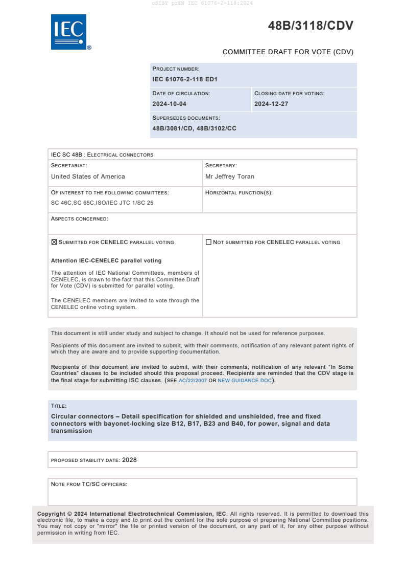
48B/3118/CDV
COMMITTEE DRAFT FOR VOTE (CDV)
PROJECT NUMBER:
IEC 61076-2-118 ED1
DATE OF CIRCULATION: CLOSING DATE FOR VOTING:
2024-10-04 2024-12-27
SUPERSEDES DOCUMENTS:
48B/3081/CD, 48B/3102/CC
IEC SC 48B : ELECTRICAL CONNECTORS
SECRETARIAT: SECRETARY:
United States of America Mr Jeffrey Toran
OF INTEREST TO THE FOLLOWING COMMITTEES: HORIZONTAL FUNCTION(S):
SC 46C,SC 65C,ISO/IEC JTC 1/SC 25
ASPECTS CONCERNED:
SUBMITTED FOR CENELEC PARALLEL VOTING NOT SUBMITTED FOR CENELEC PARALLEL VOTING
Attention IEC-CENELEC parallel voting
The attention of IEC National Committees, members of
CENELEC, is drawn to the fact that this Committee Draft
for Vote (CDV) is submitted for parallel voting.
The CENELEC members are invited to vote through the
CENELEC online voting system.
This document is still under study and subject to change. It should not be used for reference purposes.
Recipients of this document are invited to submit, with their comments, notification of any relevant patent rights of
which they are aware and to provide supporting documentation.
Recipients of this document are invited to submit, with their comments, notification of any relevant “In Some
Countries” clauses to be included should this proposal proceed. Recipients are reminded that the CDV stage is
the final stage for submitting ISC clauses. (SEE AC/22/2007 OR NEW GUIDANCE DOC).
TITLE:
Circular connectors – Detail specification for shielded and unshielded, free and fixed
connectors with bayonet-locking size B12, B17, B23 and B40, for power, signal and data
transmission
PROPOSED STABILITY DATE: 2028
NOTE FROM TC/SC OFFICERS:
electronic file, to make a copy and to print out the content for the sole purpose of preparing National Committee positions.
You may not copy or "mirror" the file or printed version of the document, or any part of it, for any other purpose without
permission in writing from IEC.
oSIST prEN IEC 61076-2-118:2024
48B/3118/CDV – 2 – IEC CDV 61076-2-118 ED1 © IEC 2024
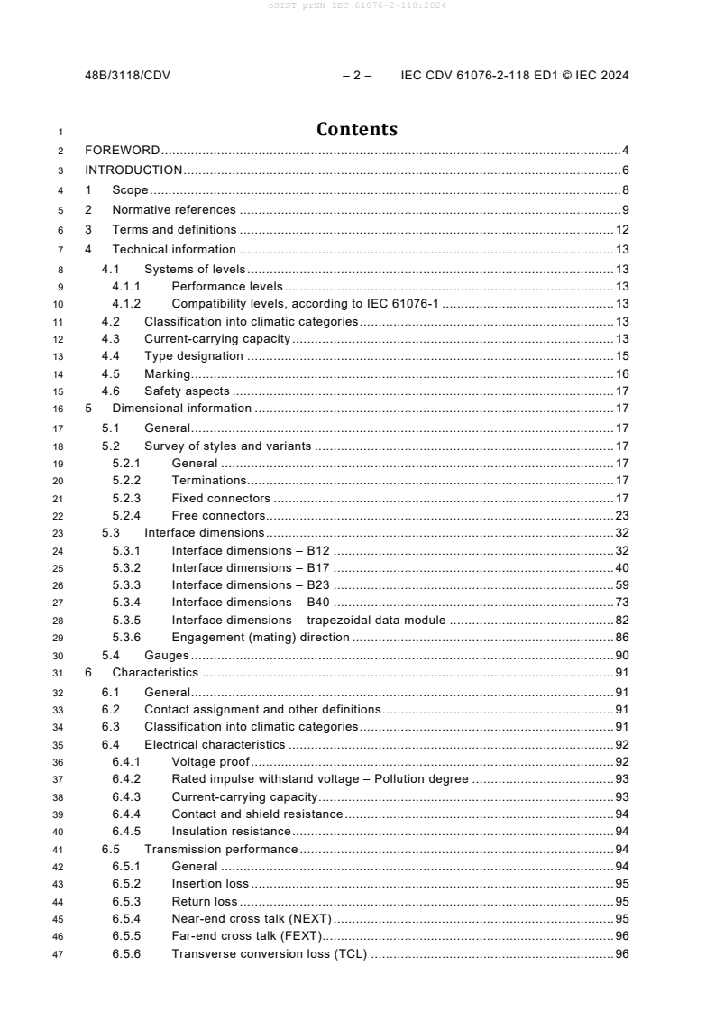
1 Contents
2 FOREWORD . 4
3 INTRODUCTION . 6
4 1 Scope . 8
5 2 Normative references . 9
6 3 Terms and definitions . 12
7 4 Technical information . 13
8 4.1 Systems of levels . 13
9 4.1.1 Performance levels . 13
10 4.1.2 Compatibility levels, according to IEC 61076-1 . 13
11 4.2 Classification into climatic categories . 13
12 4.3 Current-carrying capacity . 13
13 4.4 Type designation . 15
14 4.5 Marking . 16
15 4.6 Safety aspects . 17
16 5 Dimensional information . 17
17 5.1 General . 17
18 5.2 Survey of styles and variants . 17
19 5.2.1 General . 17
20 5.2.2 Terminations. 17
21 5.2.3 Fixed connectors . 17
22 5.2.4 Free connectors. 23
23 5.3 Interface dimensions . 32
24 5.3.1 Interface dimensions – B12 . 32
25 5.3.2 Interface dimensions – B17 . 40
26 5.3.3 Interface dimensions – B23 . 59
27 5.3.4 Interface dimensions – B40 . 73
28 5.3.5 Interface dimensions – trapezoidal data module . 82
29 5.3.6 Engagement (mating) direction . 86
30 5.4 Gauges . 90
31 6 Characteristics . 91
32 6.1 General . 91
33 6.2 Contact assignment and other definitions . 91
34 6.3 Classification into climatic categories . 91
35 6.4 Electrical characteristics . 92
36 6.4.1 Voltage proof . 92
37 6.4.2 Rated impulse withstand voltage – Pollution degree . 93
38 6.4.3 Current-carrying capacity . 93
39 6.4.4 Contact and shield resistance . 94
40 6.4.5 Insulation resistance . 94
41 6.5 Transmission performance . 94
42 6.5.1 General . 94
43 6.5.2 Insertion loss . 95
44 6.5.3 Return loss . 95
45 6.5.4 Near-end cross talk (NEXT) . 95
46 6.5.5 Far-end cross talk (FEXT). 96
47 6.5.6 Transverse conversion loss (TCL) . 96
oSIST prEN IEC 61076-2-118:2024
IEC CDV 61076-2-118 ED1 © IEC 2024 – 3 – 48B/3118/CDV
48 6.5.7 Transverse conversion transfer loss (TCTL) . 96
49 6.5.8 Transfer impedance . 97
50 6.5.9 Coupling attenuation . 97
51 6.5.10 Power sum alien (exogenous) NEXT (PS NEXT) . 97
52 6.5.11 Power sum alien (exogenous) FEXT (PS AFEXT) . 98
53 6.5.12 Propagation delay . 98
54 6.6 Mechanical characteristics . 98
55 6.6.1 Mechanical operations . 98
56 6.6.2 Effectiveness of connector coupling device . 99
57 6.6.3 Insertion and withdrawal forces . 99
58 6.6.4 Polarization and coding . 99
59 6.7 Other characteristics . 100
60 6.7.1 Vibration (sinusoidal) . 100
61 6.7.2 Shock . 100
62 6.7.3 Degree of protection provided by enclosures (IP code) . 100
63 6.7.4 Locking and unlocking torque . 100
64 7 Test schedule . 101
65 7.1 General . 101
66 7.1.1 Overview . 101
67 7.1.2 Climatic category . 101
68 7.1.3 Arrangement for contact resistance measurements . 101
69 7.1.4 Arrangement for dynamic stress tests (vibration) . 103
70 7.1.5 Wiring of specimens . 104
71 7.2 Test schedule . 104
72 7.2.1 Test group P – Preliminary . 104
73 7.2.2 Test group AP – Dynamic / Climatic . 105
74 7.2.3 Test group BP – Mechanical endurance . 108
75 7.2.4 Test group CP – Electrical load . 109
76 7.2.5 Test group DP – Connection method tests . 110
77 7.2.6 Test group EP – Signal integrity requirements . 111
78 7.2.7 Test group FP – Current carrying capacity . 111
oSIST prEN IEC 61076-2-118:2024
48B/3118/CDV – 4 – IEC CDV 61076-2-118 ED1 © IEC 2024
81 INTERNATIONAL ELECTROTECHNICAL COMMISSION
82 ____________
84 CONNECTORS FOR ELECTRICAL AND ELECTRONIC EQUIPMENT –
85 PRODUCT REQUIREMENTS –
87 Part 2-118: Circular connectors – Detail specification for shielded and
88 unshielded, free and fixed connectors with bayonet-locking size B12, B17,
89 B23 and B40, for power, signal and data transmission
92 FOREWORD
93 1) The International Electrotechnical Commission (IEC) is a worldwide organization for standardization comprising
94 all national electrotechnical committees (IEC National Committees). The object of IEC is to promote international
95 co-operation on all questions concerning standardization in the electrical and electronic fields. To this end and
96 in addition to other activities, IEC publishes International Standards, Technical Specifications, Technical Reports,
97 Publicly Available Specifications (PAS) and Guides (hereafter referred to as "IEC Publication(s)"). Their
98 preparation is entrusted to technical committees; any IEC National Committee interested in the subject dealt with
99 may participate in this preparatory work. International, governmental and non-governmental organizations liaising
100 with the IEC also participate in this preparation. IEC collaborates closely with the International Organization for
101 Standardization (ISO) in accordance with conditions determined by agreement between the two organizations.
102 2) The formal decisions or agreements of IEC on technical matters express, as nearly as possible, an international
103 consensus of opinion on the relevant subjects since each technical committee has representation from all
104 interested IEC National Committees.
105 3) IEC Publications have the form of recommendations for international use and are accepted by IEC National
106 Committees in that sense. While all reasonable efforts are made to ensure that the technical content of IEC
107 Publications is accurate, IEC cannot be held responsible for the way in which they are used or for any
108 misinterpretation by any end user.
109 4) In order to promote international uniformity, IEC National Committees undertake to apply IEC Publications
110 transparently to the maximum extent possible in their national and regional publications. Any divergence between
111 any IEC Publication and the corresponding national or regional publication shall be clearly indicated in the latter.
112 5) IEC itself does not provide any attestation of conformity. Independent certification bodies provide conformity
113 assessment services and, in some areas, access to IEC marks of conformity. IEC is not responsible for any
114 services carried out by independent certification bodies.
115 6) All users should ensure that they have the latest edition of this publication.
116 7) No liability shall attach to IEC or its directors, employees, servants or agents including individual experts and
117 members of its technical committees and IEC National Committees for any personal injury, property damage or
118 other damage of any nature whatsoever, whether direct or indirect, or for costs (including legal fees) and
119 expenses arising out of the publication, use of, or reliance upon, this IEC Publication or any other IEC
120 Publications.
121 8) Attention is drawn to the Normative references cited in this publication. Use of the referenced publications is
122 indispensable for the correct application of this publication.
123 9) IEC draws attention to the possibility that the implementation of this document may involve the use of (a)
124 patent(s). IEC takes no position concerning the evidence, validity or applicability of any claimed patent rights in
125 respect thereof. As of the date of publication of this document, IEC had not received notice of (a) patent(s), which
126 may be required to implement this document. However, implementers are cautioned that this may not represent
127 the latest information, which may be obtained from the patent database available at https://patents.iec.ch. IEC
128 shall not be held responsible for identifying any or all such patent rights.
129 IEC 61076-2-118 has been prepared by subcommittee 48B: Electrical connectors, of IEC
130 technical committee 48: Electrical connectors and mechanical structures for electrical and
131 electronic equipment. It is an International Standard.
132 The text of this International Standard is based on the following documents:
Draft Report on voting
48B/XX/FDIS 48B/XX/RVD
oSIST prEN IEC 61076-2-118:2024
IEC CDV 61076-2-118 ED1 © IEC 2024 – 5 – 48B/3118/CDV
134 Full information on the voting for its approval can be found in the report on voting indicated in
135 the above table.
136 The language used for the development of this International Standard is English.
137 This document was drafted in accordance with ISO/IEC Directives, Part 2, and developed in
138 accordance with ISO/IEC Directives, Part 1 and ISO/IEC Directives, IEC Supplement, available
139 at www.iec.ch/members_experts/refdocs. The main document types developed by IEC are
140 described in greater detail at www.iec.ch/publications.
141 The committee has decided that the contents of this document will remain unchanged until the
142 stability date indicated on the IEC website under webstore.iec.ch in the data related to the
143 specific document. At this date, the document will be
144 • reconfirmed,
145 • withdrawn,
146 • replaced by a revised edition, or
147 • amended.
IMPORTANT – The "colour inside" logo on the cover page of this document indicates
that it contains colours which are considered to be useful for the correct understanding
of its contents. Users should therefore print this document using a colour printer.
oSIST prEN IEC 61076-2-118:2024
48B/3118/CDV – 6 – IEC CDV 61076-2-118 ED1 © IEC 2024
150 INTRODUCTION
IEC SC 48B – Electrical connectors IEC 61076-2-118 ED1
Specification available from:
IEC General secretariat
or from the addresses shown on the inside cover.
DETAIL SPECIFICATION in accordance with IEC 61076-1
Circular connectors
With bayonet-locking
Size B12, B17, B23 and B40,
for power, signal and data
transmission
Male (power and signal) +
male (data) and female
(power and signal) + female
(data) connectors
Male (power and signal) +
female (data) and female
(power and signal) + male
(data) connectors
Male and female contacts
Shielded and unshielded
Rewirable
Non-rewirable
Free connectors
Straight and angled
connectors
Fixed connectors
Flange mounting
Single hole mounting
oSIST prEN IEC 61076-2-118:2024
IEC CDV 61076-2-118 ED1 © IEC 2024 – 7 – 48B/3118/CDV
153 The International Electrotechnical Commission (IEC) draws attention to the fact that it is claimed
154 that compliance with this document may involve the use of a patent. IEC takes no position
155 concerning the evidence, validity, and scope of this patent right.
156 The holder of this patent right has assured IEC that s/he is willing to negotiate licences under
157 reasonable and non-discriminatory terms and conditions with applicants throughout the world.
158 In this respect, the statement of the holder of this patent right is registered with IEC. Information
159 may be obtained from the patent database available at patents.iec.ch/.
160 Attention is drawn to the possibility that some of the elements of this document may be the
161 subject of patent rights other than those in the patent database. IEC shall not be held
162 responsible for identifying any or all such patent rights.
oSIST prEN IEC 61076-2-118:2024
48B/3118/CDV – 8 – IEC CDV 61076-2-118 ED1 © IEC 2024
165 CONNECTORS FOR ELECTRICAL AND ELECTRONIC EQUIPMENT –
166 PRODUCT REQUIREMENTS –
168 Part 2-118: Circular connectors –
169 Detail specification for free and fixed connectors with bayonet-locking
170 size B12, B17, B23 and B40, for power, signal and data transmission
173 1 Scope
174 This part of IEC 61076 specifies circular connectors with size B12, B17, B23 and B40 with
175 bayonet-locking, typically used for power, signal and data transmissions in industrial
176 applications. These connectors consist of fixed and free connectors either rewirable or non-
177 rewirable.
178 Power contacts of male connectors are round contacts with Ø 1 mm, Ø 1,5 mm, Ø 1,8 mm,
179 Ø 2,25 mm and Ø 4 mm, with current ratings up to 64 A per pole and rated voltage of 50 V, 300
180 V or 600 V AC/DC. Power contact groups are classified by type and identified throughout this
181 document as “P” followed by two digits “01” through “09” (see 4.3, Table 1).
182 Signal contacts of male connectors are round contacts with Ø 1 mm and Ø 1,8 mm, with current
183 ratings up to 20 A per pole and rated voltage of 50 V AC/DC. Signal contact groups are classified
184 by type and identified throughout this document as “S” followed by “0”, “1”, or “2” (see 4.3,
185 Table 2).
186 Data contacts of male connectors are round contacts with Ø 0,8 mm and Ø 1 mm, with current
187 ratings up to 8 A and rated voltage of 50 V AC/DC, Data transmission performance with
188 frequencies up to 600 MHz. Data modules are classified by type and identified throughout this
189 standard as “D” followed by “1”, or “2” (see 4.3, Table 3).
190 Besides the size of their bayonet locking (B12, B17, B23 or B40), connectors according to this document
191 can be identified by data module (D) and complementing power (P) and signal (S) contact groups and
192 optionally by number of poles, and finally by their application.
193 These connectors are designated for two main target applications, which differ as follows:
194 • Application A is for data transmission with power over data
195 • Application B is for data transmission without power over data
196 Connectors with power, signal and data contacts of the same gender are intended to transmit also power
197 over the data contacts (application A), while connectors with data contacts not of the same gender of
198 power and signal contacts are not intended to transmit power over the data contacts (application B).
199 The codings provided by this document prevent the mating to any other connector with similary
200 sized interfaces covered by this document.
201 NOTE: B indicates that the connector is equipped with bayonet locking, while 12, 17, 23, 40 are the approximate
202 dimensions in millimetres of the contact carrier diameter of these circular connectors.
oSIST prEN IEC 61076-2-118:2024
IEC CDV 61076-2-118 ED1 © IEC 2024 – 9 – 48B/3118/CDV
205 2 Normative references
206 The following documents are referred to in the text in such a way that some or all of their content
207 constitutes requirements of this document. For dated references, only the edition cited applies.
208 For undated references, the latest edition of the referenced document (including any
209 amendments) applies.
210 IEC 60050-581:2008, International Electrotechnical Vocabulary – Part 581: Electromechanical
211 components for electronic equipment
212 IEC 60068-1, Environmental testing – Part 1: General and guidance
213 IEC 60352-2, Solderless connections – Part 2: Crimped connections – General requirements,
214 test methods and practical guidance
215 IEC 60352-3, Solderless connections – Part 3: Solderless accessible insulation displacement
216 connections – General requirements, test methods and practical guidance
217 IEC 60352-4, Solderless connections – Part 4: Solderless non-accessible insulation
218 displacement connections – General requirements, test methods and practical guidance
219 IEC 60352-5, Solderless connections – Part 5: Press-in connections – General requirements,
220 test methods and practical guidance
221 IEC 60352-6, Solderless connections – Part 6: Insulation piercing connections – General
222 requirements, test methods and practical guidance
223 IEC 60352-7, Solderless connections – Part 7: Spring clamp connections – General
224 requirements, test methods and practical guidance
225 IEC 60352-9, Solderless connections – Part 9: Ultrasonically welded connections – General
226 requirements, test methods and practical guidance
228 IEC 60512-1-1, Connectors for electronic equipment – Tests and measurements – Part 1-1:
229 General examination – Test 1a: Visual examination
230 IEC 60512-1-2, Connectors for electronic equipment – Tests and measurements – Part 1-2:
231 General examination – Test 1b: Examination of dimension and mass
232 IEC 60512-2-1, Connectors for electronic equipment – Tests and measurements – Part 2-1:
233 Electrical continuity and contact resistance tests – Test 2a: Contact resistance – Millivolt level
234 method
235 IEC 60512-3-1, Connectors for electronic equipment – Tests and measurements – Part 3-1:
236 Insulation tests – Test 3a: Insulation resistance
237 IEC 60512-4-1, Connectors for electronic equipment – Tests and measurements – Part 4-1:
238 Voltage stress tests – Test 4a: Voltage proof
239 IEC 60512-5-1, Connectors for electronic equipment – Tests and measurements – Part 5-1:
240 Current-carrying capacity tests – Test 5a: Temperature rise
241 IEC 60512-6-3, Connectors for electronic equipment – Tests and measurements – Part 6-3:
242 Dynamic stress tests – Test 6c: Shock
oSIST prEN IEC 61076-2-118:2024
48B/3118/CDV – 10 – IEC CDV 61076-2-118 ED1 © IEC 2024
243 IEC 60512-6-4, Connectors for electronic equipment – Tests and measurements – Part 6-4:
244 Dynamic stress tests – Test 6d: Vibration (sinusoidal)
245 IEC 60512-9-1, Connectors for electronic equipment – Tests and measurements – Part 9-1:
246 Endurance tests – Test 9a: Mechanical operation
247 IEC 60512-9-2, Connectors for electronic equipment – Tests and measurements – Part 9-2:
248 Endurance tests – Test 9b: Electrical load and temperature
249 IEC 60512-11-1, Electromechanical components for electronic equipment – Basic testing
250 procedures and measuring methods – Part 11: Climatic tests – Section 1: Test 11a – Climatic
251 sequence
252 IEC 60512-11-4, Connectors for electronic equipment – Tests and measurements – Part 11-4:
253 Climatic tests – Test 11d: Rapid change of temperature
254 IEC 60512-11-9, Connectors for electronic equipment – Tests and measurements – Part 11-9:
255 Climatic tests – Test 11i: Dry heat
256 IEC 60512-11-10, Connectors for electronic equipment – Tests and measurements – Part 11-
257 10: Climatic tests – Test 11j: Cold
258 IEC 60512-11-12, Connectors for electronic equipment – Tests and measurements – Part 11-
259 12: Climatic tests – Test 11m: Damp heat, cyclic
260 IEC 60512-13-2, Connectors for electronic equipment – Tests and measurements – Part 13-2:
261 Mechanical operation tests – Test 13b: Insertion and withdrawal forces
262 IEC 60512-13-5, Connectors for electronic equipment – Tests and measurements – Part 13-5:
263 Mechanical operation tests – Test 13e: Polarizing and keying method
264 IEC 60512-16-5, Connectors for electronic equipment – Tests and measurements – Part 16-5:
265 Mechanical tests on contacts and terminations – Test 16e: Gauge retention force (resilient
266 contacts)
267 IEC 60512-28-100, Connectors for electrical and electronic equipment - Tests and
268 measurements - Part 28-100: Signal integrity tests up to 2 000 MHz - Tests 28a to 28g
269 IEC 60529:1989, Degrees of protection provided by enclosures (IP Code)
270 IEC 60529:1989/AMD1:1999
271 IEC 60529:1989/AMD2:2013
272 IEC 60664-1, Insulation coordination for equipment within low-voltage systems – Part 1:
273 Principles, requirements and tests
274 IEC 60999-1, Connecting devices – Electrical copper conductors – Safety requirements for
275 screw-type and screwless-type clamping units – Part 1: General requirements and particular
276 requirements for clamping units for conductors from 0,2 mm2 up to 35 mm2 (included)
277 IEC 61076-1:2006, Connectors for electronic equipment – Product requirements – Part 1:
278 Generic specification
279 IEC 61984, Connectors – Safety requirements and tests
oSIST prEN IEC 61076-2-118:2024
IEC CDV 61076-2-118 ED1 © IEC 2024 – 11 – 48B/3118/CDV
280 IEC 62197-1, Connectors for electronic equipment – Quality assessment requirements – Part
281 1: Generic specification
282 ISO 11469, Plastics – Generic identification and marking of plastics products
283 ISO 21920-1:2021, Geometrical product specifications (GPS) - Surface texture: Profile - Part 1:
284 Indication of surface texture
oSIST prEN IEC 61076-2-118:2024
48B/3118/CDV – 12 – IEC CDV 61076-2-118 ED1 © IEC 2024
286 3 Terms and definitions
287 For the purposes of this document, the terms and definitions given in IEC 61076-1, IEC 61076-
288 2, IEC 60512-1, IEC 61984 and the following apply.
289 ISO and IEC maintain terminology databases for use in standardization at the following
290 addresses:
291 • IEC Electropedia: available at https://www.electropedia.org/
292 • ISO Online browsing platform: available at https://www.iso.org/obp
294 3.1
295 protective conductor
296 PE
297 conductor provided for purposes of safety, for example protection against electric shock
298 Note to entry: In an electrical installation, the conductor identified PE is normally also considered as protective
299 earthing conductor.
300 [SOURCE: IEC 60050-581:2008, 581-27-26]
301 3.2
302 mounting orientation
303 circular mounting position of the connector in relation to the polarization of the mating interface
304 Note to entry: Where the free connector has an angled cable entry (as opposed to a straight cable entry), the angle
305 between the cable entry direction and the polarization keyway should be specified.
oSIST prEN IEC 61076-2-118:2024
IEC CDV 61076-2-118 ED1 © IEC 2024 – 13 – 48B/3118/CDV
307 4 Technical information
308 4.1 Systems of levels
309 4.1.1 Performance levels
310 Performance levels for these connectors are specified in 6.6.1 Table 73.
311 4.1.2 Compatibility levels, according to IEC 61076-1
312 Connectors according to this document are intermateable according to IEC 61076-1.
313 4.2 Classification into climatic categories
314 Classification into climatic categories is specified in 6.3 Table 59
315 4.3 Current-carrying capacity
316 Current rating of each part of the connectors (power, signal, data) shall be according to Table
317 1 to Table 3.
318 All contact groups concurrently loaded, each at its rated current.
319 Table 1 – Ratings of connector power part
Rated voltage
Male
AC or DC Rated current
contact Ø
Number of
Type contacts Function mm V A
P01 2-pin 2 1 50 8
P02 3-pin 2 + PE 1,8 300 20
P03 3-pin 2 + PE 16
P04 4-pin 3 + PE
1,5 14
P05 5-pin 4 + PE
P06 4-pin 3 + PE 600 12
P07 5-pin 4 + PE
2,25 26
P08 4-pin 3 + PE
P09 5-pin 4 + PE 4 64
NOTE 1: The current-carrying capacity depends on the terminated wire size and other influences.
NOTE 2: Reduced rating of P6 and P8 due to the connector signal part
oSIST prEN IEC 61076-2-118:2024
48B/3118/CDV – 14 – IEC CDV 61076-2-118 ED1 © IEC 2024
322 Table 2 – Ratings of connector signal part
Rated voltage
Male contact Ø AC or DC Rated current
Type Number of contacts mm V A
S0 No signal contacts - - -
S1 2-pin 1,8 50 20
S2 2-pin 1 50 8
NOTE 1: The current-carrying capacity depends on the terminated wire size and other influences.
324 Table 3 – Ratings of connector data part (data module)
Rated voltage
Male contact Ø AC or DC Rated current
Type Number of contacts mm V A
D1 4-pin 0,8 50 4
D2 2-pin 1 50 8
NOTE 1: The current-carrying capacity depends on the terminated wire size and other influences.
oSIST prEN IEC 61076-2-118:2024
IEC CDV 61076-2-118 ED1 © IEC 2024 – 15 – 48B/3118/CDV
327 4.4 Type designation
328 Type designation is defined as follows:
329 – the first three digits denotes the connector size (B12, B17, B23 or B40);
th th
330 – the 4 and 5 digit denotes the power contact group type (see 4.3 Table 1);
th
331 – the 6 digit denotes the signal contact group type (see 4.3 Table 2)
th
332 – the 7 digit denotes the data module type (see 4.3 Table 3);
th
333 – the 8 digit denotes the application of the connector (A or B as describes in 1)
334 See Table 4 for details.
335 Table 4 – Type designation
B 1 7 0 1 0 1 1
Application type
1 A
2 B
Data module type
1 D1
2 D2
Signal contacts type
0 S0
1 S1
2 S2
Power contacts type
01 P01
02 P02
03 P03
04 P04
05 P05
06 P06
07 P07
08 P08
09 P09
Size
B12
B17
B23
B40
oSIST prEN IEC 61076-2-118:2024
48B/3118/CDV – 16 – IEC CDV 61076-2-118 ED1 © IEC 2024
337 Table 5 – Combination possibilities of power, signal and data
Combination of types (see Number of Applic
Type Size Function
Table 1, Table 2, Table 3) contacts ation
B1201011 A
P01 + S0 + D1 6-pin 2×P + 4×D
B1201012 B
B12
B1201021 A
P01 + S0 + D2 4-pin 2×P + 2×D
B1201022 B
B1702011 A
P02 + S0 + D1 7-pin 2×P + PE + 4×D
B1702012 B
B1702021 A
P02 + S0 + D2 5-pin 2×P + PE + 2×D
B1702022 B
B1703011 A
P03 + S0 + D1 7-pin 2×P + PE + 4×D
B1703012 B
B1703021 A
P03 + S0 + D2 5-pin 2×P + PE + 2×D
B1703022 B
B1704011 A
P04 + S0 + D1 8-pin 3×P + PE + 4×D
B1704012 B
B17
B1704021 A
P04 + S0 + D2 6-pin 3×P + PE + 2×D
B1704022 B
B1705011 A
P05 + S0 + D1 9-pin 4×P + PE + 4×D
B1705012 B
B1705021 A
P05 + S0 + D2 7-pin 4×P + PE + 2×D
B1705022 B
B1706211 A
P06 + S2 + D1 10-pin 3×P + PE + 2×S + 4×D
B1706212 B
B1706221 A
P06 + S2 + D2 8-pin 3×P + PE + 2×S + 2×D
B1706222 B
B2307011 A
P07 + S0 + D1 9-pin 4×P+ PE + 4×D
B2307012 B
B2307021 A
P07 + S0 + D2 7-pin 4×P+ PE + 2×D
B2307022 B
B23
B2308111 A
P08 + S1 + D1 10-pin 3×P + PE + 2×S + 4×D
B2308112 B
B2308121 A
P08 + S1 + D2 8-pin 3×P + PE + 2×S + 2×D
B2308122 B
B4009011 A
P09 + S0 + D1 9-pin 4×P+ PE + 4×D
B4009012 B
B40
B4009021 A
P09 + S0 + D2 7-pin 4×P+ PE + 2×D
B4009022
B
NOTE: Application A and B connectors with the same type are not intermateable due to inverse gender of the data
contacts.
340 4.5 Marking
341 The marking of the connector and the package shall be in accordance with 2.7 of IEC 61076-
342 1:2006.
oSIST prEN IEC 61076-2-118:2024
IEC CDV 61076-2-118 ED1 © IEC 2024 – 17 – 48B/3118/CDV
343 4.6 Safety aspects
344 For safety aspects, IEC 61984 shall apply.
345 Size B12 connectors covered by this document are only for extra-low voltage (ELV) applications
346 being without PE contact. For these, IEC 61984 is applicable as a guidance.
347 5 Dimensional information
348 5.1 General
349 Throughout this standard, dimensions are in mm. Drawings are shown in the first angle
350 projection. The shape of the connectors may deviate from those given in the following drawings
351 as long as the specified dimensions are not influenced.
352 Missing dimensions shall be chosen according to common characteristics and intended use.
353 5.2 Survey of styles and variants
354 5.2.1 General
355 For all connector styles with cables, the length L of the cable shall be agreed between
356 manufacturer and user. For interface dimensions see 5.3.
357 Alternative installation situations are possible and shall be specified upon between
358 manufacturer and user. Requirements defined in this document must be adhered to.
359 5.2.2 Terminations
360 The contact terminations shall be suitable for the following types of connection: wrapped, crimped,
361 accessible insulation displacement (ID), non-accessible insulation displacement (ID), press-in,
362 insulation piercing, spring clamp, ultrasonically welded connections according to IEC 60352 series,
363 screw-type or screwless-type connections according to IEC 60999-1, or solder connections.
364 5.2.3 Fixed connectors
365 5.2.3.1 General
366 Table 6 shows styles of fixed connectors.
367 Table 6 – Styles of fixed connectors
Style Description
Fixed connector, with wire ends, male power contacts, data contacts, with bayonet locking notch,
DM square flange front mounting
Fixed connector, with wire ends, male power contacts, data contacts, with bayonet locking notch,
EM single hole front mounting, keyway orientation
Fixed connector, with wire ends, male power contacts, data contacts, with bayonet locking notch,
FM single hole rear mounting, keyway orientation
Fixed connector, with wire ends, female power contacts, data contacts, with bayonet locking notch,
DF square flange front mounting
Fixed connector, with wire ends, female power contacts, data contacts, with bayonet locking notch,
EF single hole front mounting, keyway orientation
Fixed connector, with wire ends, female power contacts, data contacts, with bayonet locking notch,
FF single hole rear mounting, keyway orientation
NOTE: Depending on the application A or B data contacts could be male or female
oSIST prEN IEC 61076-2-118:2024
48B/3118/CDV – 18 – IEC CDV 61076-2-118 ED1 © IEC 2024
370 5.2.3.2 Style DM
371 Figure 1 shows a fixed connector with male power contacts, with wire ends, with bayonet locking
372 notch, square flange front mounting. Depending on the application A or B data contacts could
373 be male or female.
375 Figure 1 – Fixed connector, with wire ends, male power contacts, male data contacts,
376 with bayonet locking notch, square flange front mounting
377 Table 7 shows the related dimensions.
378 Table 7 – Dimensions of style DM
379 Dimensions in millimetres
Size L1 max. L2 max. A max. B Ø D max. C Ø F min. Ø G
B12 37 33 20 14 2,8 14 16,2 2,8 max.
B17 40 36 25 19,8 2,8 19,8 20,6 2,8 max.
B23 48 44 26 19,8 3,3 19,8 20 3,3 max.
B40 66 62 45 30 4,5 30 32 4,5 max.
381 5.2.3.3 Style EM
382 Figure 2 shows a fixed connector with male power contacts, with wire ends, with bayonet
383 locking notch, single hole front mounting, keyway orientation. Depending on the application A
384 or B data contacts could be male or female.
386 Figure 2 – Fixed connector, with wire ends, male power contacts, male data contacts,
387 with bayonet locking notch, single hole front mounting, keyway orientation
oSIST prEN IEC 61076-2-118:2024
IEC CDV 61076-2-118 ED1 © IEC 2024 – 19 – 48B/3118/CDV
388 Table 8 shows the related dimensions.
389 Table 8 – Dimensions of style EM
390 Dimensions in millimetres
L1 L2 W max. Ø C E min.
Size A B Ø D max.
max. max. (optional) min. (optional)
B12 37 28 M18 × 1 SW 24 27 16,5 18,2 16,7
B17 40 31 M24 × 1 SW 30 33 22 24,2 22,2
B23 48 39 M25 × 1 SW 30 33 23,8 25,2 24
B40 70 60. M42 × 1,5 SW 47 52 40 42,2 40,2
393 5.2.3.4 Style FM
394 Figure 3 shows a fixed connector with male power contacts, with wire ends, with bayonet
395 locking notch, single hole rear mounting, keyway orientation. Depending on the application A
396 or B data contacts could be male or female.
398 Figure 3 – Fixed connector, with wire ends, male power contacts, male data contacts,
399 with bayonet locking notch, single hole rear mounting, keyway orientation
400 Table 9 shows the related dimensions.
401 Table 9 – Dimensions of style FM
402 Dimensions in millimetres
L1 L2 W max.
Size A B Ø D max. Ø C min. E min. (optional)
max. max. (optional)
B12 37 33 M18 × 1 SW 24 27 16,5 18,2 16,7
B17 40 36 M24 × 1 SW 30 33 22 24,2 22,2
B23 48 44 M25 × 1 SW 30 33 23,8 25,2 24
B40 70 66 M42 × 1,5 SW47 52 40 42,2 40,2
oSIST prEN IEC 61076-2-118:2024
48B/3118/CDV – 20 – IEC CDV 61076-2-118 ED1 © IEC 2024
404 5.2.3.5 Style DF
405 Figure 4 shows a fixed connector with female power contacts, with wire ends, with bayonet
406 locking notch, square flange front mounting. Depending on the application A or B data
407 contacts could be female or male.
410 Figure 4 – Fixed connector, with wire ends, female power contacts, female data
411 contacts, with bayonet locking notch, square flange front mounting
412 Table 10 shows the related dimensions.
413 Table 10 – Dimensions of style DF
414 Dimensions in millimetres
A
Size L1 max. L2 max. B Ø D max. C Ø F min. Ø G
max.
B12 37 33 20 14 2,8 14 16,2 2,8 max.
B17 43 39 25 19,8 2,8 19,8 20,6 2,8 max.
B23 43 39 26 19,8 3,3 19,8 20 3,3 max.
B40 61 57 45 30 4,5 30 32 4,5 max.
416 5.2.3.6 Style EF
417 Figure 5 shows a fixed connector with female power contacts, with wire ends, with bayonet
418 locking notch, single hole front mounting, keyway orientation. Depending on the application A
419 or B data contacts could be female or male.
oSIST prEN IEC 61076-2-118:2024
IEC CDV 61076-2-118 ED1 © IEC 2024 – 21 – 48B/3118/CDV
421 Figure 5 – Fixed connector, with wire ends, female power contacts, female data
422 contacts, with bayonet locking notch, single hole front mounting, keyway orientation
423 Table 11 shows the related dimensions.
424 Table 11 – Dimensions of style EF
425 Dimensions in millimetres
W max.
Size L1 max. L2 max. A B Ø D max. Ø C min. E min. (optional)
(optional)
B12 37 28 M18 × 1 SW 24 27 16,5 18,2 16,7
B17 43 34 M24 × 1 SW 30 33 22 24,2 22,2
B23 43 34 M25 × 1 SW 30 33 23,8 25,2 24
B40 70 60 M42 ×1,5 SW 47 52 40 42,2 40,2
427 5.2.3.7 Style FF
428 Figure 6 shows a fixed connector with female power contacts, with wire ends, with bayonet
429 locking notch, single hole rear mounting, keyway orientation. Depending on the application A
430 or B data contacts could be female or male.
433 Figure 6 – Fixed connector, with wire ends, female power contacts, female data
434 contacts, with bayonet locking notch, single hole rear mounting, keyway orientation
oSIST prEN IEC 61076-2-118:2024
48B/3118/CDV – 22 – IEC CDV 61076-2-118 ED1 © IEC 2024
435 Table 12 shows the related dimensions.
436 Table 12 – Dimensions of style FF
437 Dimensions in millimetres
L1 L2 Ø D W max. E min (optional)
Size A B Ø C min.
max. max. max. (optional)
B12 37 33 M18 × 1 SW24 26 16,5 18,2 16,7
B17 43 39 M24 × 1 SW30 32 22 24,2 22,2
B23 43 39 M25 × 1 SW30 32 23,8 25,2 24
40 42,2 40,2
B40 70 65 M42 × 1,5 SW47 52
oSIST prEN IEC 61076-2-118:2024
IEC CDV 61076-2-118 ED1 © IEC 2024 – 23 – 48B/3118/CDV
439 5.2.4 Free connectors
440 5.2.4.1 General
441 The gender of the connectors described in Figures 7 through Figure 18 is that of their power contacts.
442 Data module can have either the same gender (connectors for appl
...