

oSIST prEN 16891:2027
(Main)Railway applications - Acoustics - Measurement method for combined roughness, track decay rates and transfer functions
- Abstract
The method described in this document is used to determine combined wheel-rail roughness and track decay rates from rail vibration during the pass-by of a train. By combining sound pressure measurement from the same pass-by, a vibro-acoustic transfer function for rolling noise is determined.
This document describes a method for the following purposes:
- to measure track decay rates under operational conditions;
- to characterize the effectiveness of noise control measures in terms of combined roughness, transfer function and track decay rate;
- to compare the combined roughness before and after noise control measures are implemented (thereby quantifying the effect of any change in wheel or rail roughness);
- to monitor wheel roughness during a pass-by, either of whole trains or parts of trains;
- to separate rolling noise from other sources;
- to assess a threshold for the rail roughness, by measuring multiple pass-bys;
- to obtain combined roughness and transfer functions for input to environmental noise calculations.
The method is not for approval of sections of reference track in terms of acoustic rail roughness and track decay rates, which are covered by EN 15610:2019+A1:2025 [9] and EN 15461:2008+A1:2010 [10], respectively.
The method is applicable to trains on conventional tracks, i.e. normal ballasted tracks with wooden or concrete sleepers and on slab tracks.
Annex A and Formula (A.1) give guidance on the calculation of the A2 factor, if the method is applied to:
- non-standard wheel types such as small wheels, resilient tram wheels;
- non-standard track types such as embedded rail or grooved rail.
- Status
- Not Published
- Public Enquiry End Date
- 31-Jan-2027
- Technical Committee
- IŽNP - Reilway applications
- Current Stage
- 4020 - Public enquire (PE) (Adopted Project)
- Start Date
- 19-Nov-2026
- Due Date
- 08-Apr-2027

oSIST prEN 16891:2027 is a CEN draft European Standard for railway acoustics. It specifies a pass-by measurement method for combined wheel-rail roughness, track decay rates, and a rolling-noise transfer function. It is aimed at railway engineers, noise specialists, and test teams that need to measure track and vehicle-related acoustic behaviour in service conditions.
What does oSIST prEN 16891:2027 specify?
oSIST prEN 16891:2027 specifies how to derive combined roughness and track decay rates from rail vibration measured during a train pass-by, and how to combine those results with sound pressure measured during the same pass-by to obtain a vibro-acoustic transfer function for rolling noise.
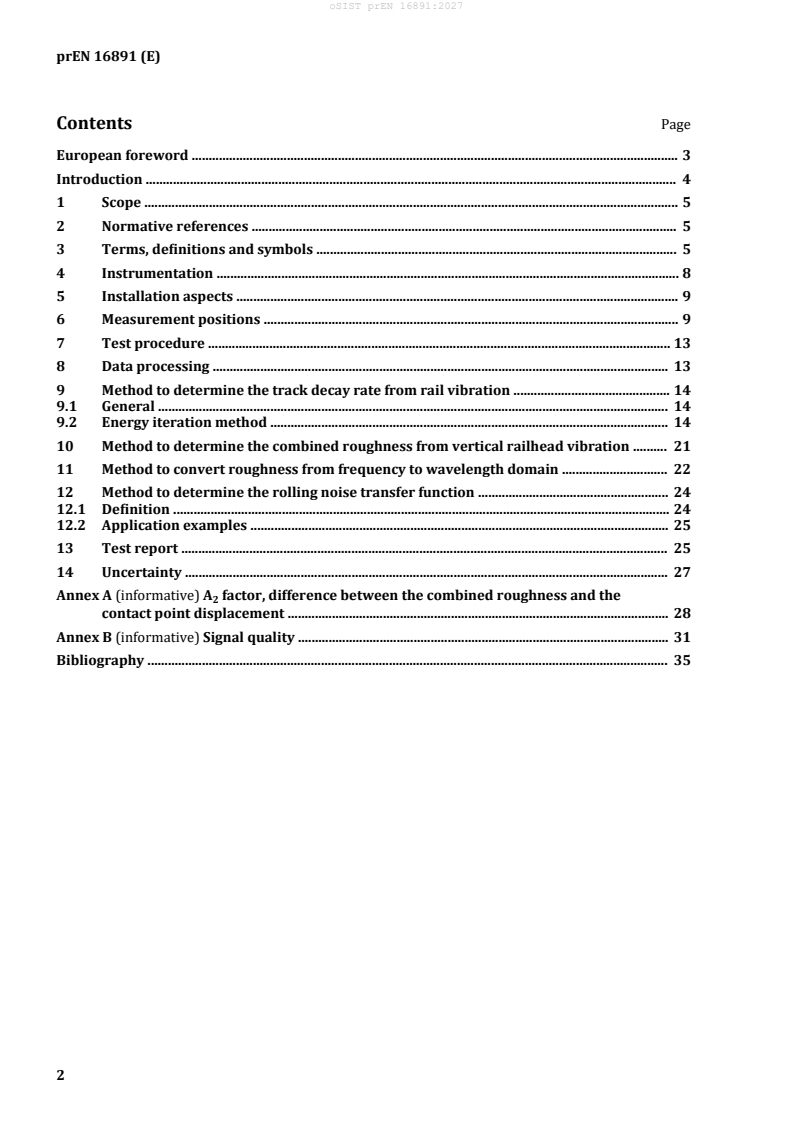
The document is organized into scope, normative references, terms and symbols, instrumentation, installation aspects, measurement positions, test procedure, data processing, separate methods for track decay rate, combined roughness, wavelength conversion, transfer function, reporting, and uncertainty.
| Annex | What it covers |
|---|---|
| Annex A | Guidance for the A factor, the difference between combined roughness and contact-point displacement, including values for typical track and wheel situations |
| Annex B | Signal quality, with examples of overload, interference, distortion, and other faulty vibration signals |
The scope limits the method to operational train measurements on conventional tracks and slab tracks. It is not used to approve reference track sections for acoustic rail roughness or track decay rates, which are covered by EN 15610:2019+A1:2025 and EN 15461:2008+A1:2010.
What are the key requirements of oSIST prEN 16891:2027?
Measurement setup and instrumentation
oSIST prEN 16891:2027 requires sound pressure measurement equipment to comply with EN ISO 3095, and the whole measurement chain must cover 25 Hz to 10 kHz. Acceleration, sound pressure, and trigger sampling must be fast enough for that band.
In practice, this means the measurement system has to capture both the rail vibration and the acoustic signal without clipping, overload, or loss of bandwidth. The standard also recommends accelerometer selection and mounting that can handle high peaks, such as wheel flats or freight wagons with high roughness.
Sensor placement and installation
oSIST prEN 16891:2027 places strong emphasis on mounting and sensor position. For vertical track decay rate and combined roughness, the accelerometer is mounted under the longitudinal axis of the rail foot, between the sleeper edge and 25% of the distance between rail fixations. For lateral decay rate, it is mounted on the outer side of the rail head. If transfer function is measured, the microphone is placed 7.5 m from the track centreline and 1.2 m above the rail surface opposite the accelerometer.
This matters because the measured signal is only useful if the sensor sits in a consistent, mechanically stable location. The document also asks for homogeneous track composition and avoidance of nearby disturbances such as damaged fasteners, welds, rail gaps, pumping sleepers, or damaged dampers.
Pass-by data that must be recorded
oSIST prEN 16891:2027 requires the following for each whole pass-by: vertical railhead vibration, lateral vibration if needed, sound pressure if transfer function is required, train speed, train length, number of axles, and optionally axle trigger signals and rail temperature.
This gives the later calculations the time alignment and train geometry needed to separate the contribution of individual wheels. The standard also allows train length to be known in advance or derived from speed and pass-by time.
Track decay rate method
oSIST prEN 16891:2027 determines vertical and lateral track decay rate by an energy iteration method applied to the vibration time signal. The method uses pass-by vibration data without wheel defects such as flats, and results are averaged over at least three pass-bys. Any third-octave result differing by more than 5 dB/m from other measurements is rejected.
The practical point is that the decay rate is not read directly from one impact, but estimated from the energy around each wheel and then iterated until the wheel-to-wheel overlap is accounted for. The standard gives the steps for band filtering, wheel-position estimation, the decay exponent, and convergence of the iteration.
Combined roughness and wavelength conversion
oSIST prEN 16891:2027 derives combined roughness from the vertical decay rate and the equivalent vertical rail vibration level over pass-by time. The result includes the contact filter, and the calculation uses an A-factor correction that represents the difference between combined roughness and contact-point displacement.
The document also converts roughness from frequency to wavelength using train speed and one-third octave preferred values. This matters because the same measured spectrum can represent different wavelength ranges at different speeds, and multiple speeds may be needed to cover the wavelength range needed for an application.
Transfer function, reporting, and uncertainty
oSIST prEN 16891:2027 defines a rolling noise transfer function from the equivalent sound pressure level, the combined roughness, and the axle density. When rolling noise is the only significant source, the transfer function can be used to compare vehicle-track combinations and to separate rolling noise from other noise sources.
The test report has to capture site details, sensors, calibration, train data, decay-rate settings, and the resulting spectra. The standard also gives an uncertainty estimate of about ±3 dB in third-octave bands when results are averaged over at least three pass-bys, with several listed influence factors such as speed, wheel position accuracy, and signal quality.
What terms does oSIST prEN 16891:2027 define?
- Pass-by time (Tp) - The duration of a vehicle pass-by from buffer to buffer, used as the main time window for averaging signals.
- Equivalent sound pressure level spectrum - The one-third octave band spectrum of sound pressure energy averaged over the pass-by time.
- Equivalent vertical rail vibration level spectrum - The one-third octave band spectrum of railhead acceleration energy averaged over the pass-by time.
- Vertical track decay rate - The rate at which vertical rail vibration decays along the rail, expressed in dB/m.
- Combined effective roughness wavelength spectrum - The one-third octave band wavelength spectrum of wheel-rail roughness including the contact filter.
- Rolling noise transfer function - The one-third octave band relationship between trackside sound pressure and combined effective roughness, normalized to axle density.
- Receptance - The transfer function between an applied excitation force and the displacement it produces at the same position.
Who uses oSIST prEN 16891:2027?
oSIST prEN 16891:2027 is used by railway acoustics specialists, infrastructure managers, rolling stock engineers, noise consultants, and testing laboratories. It is relevant for people who measure operational track conditions, compare noise control measures, assess wheel roughness during service, and prepare inputs for environmental noise calculations.
It is also useful for teams that need to separate rolling noise from aerodynamic or traction noise, or to compare different vehicle-track combinations on conventional track or slab track. In practice, it supports measurement campaigns on lines in service rather than laboratory-only testing.
What changed in oSIST prEN 16891:2027 from the previous edition?
oSIST prEN 16891:2027 supersedes CEN/TR 16891:2016. The European foreword states these technical changes:
- the former technical report has been revised and updated into a European standard;
- definitions and references to other standards have been updated;
- installation aspects and the iteration procedure have been clarified;
- the reporting clause has been expanded;
- an annex on signal quality has been added;
- Annexes B and C from the previous version, covering benchmark examples and the slope method, have been deleted.
Which standards are used with oSIST prEN 16891:2027?
oSIST prEN 16891:2027 cites several standards that support its measurement and presentation methods:
- IEC 61260-1 - defines the octave-band and fractional-octave-band filters used for signal processing.
- EN ISO 266 - provides the preferred frequencies and exact one-third octave values used for spectra and wavelength conversion.
- EN 17343 - supplies general railway terms and definitions used in the document.
- EN IEC 60263:2020 - gives the plotting scales used for reporting the spectra.
- EN ISO 3095 - supports the sound pressure measurement requirements.
- ISO 5348:2021 - gives guidance on accelerometer mounting.
- EN 15610:2019+A1:2025 - covers acoustic rail and wheel roughness measurement related to noise generation.
- EN 15461:2008+A1:2010 - covers characterisation of track dynamic properties for pass-by noise measurements.
- EN 17936:2024 - is cited for source-term separation methods and application examples.
- EN 17495:2022 - is referenced for dynamic stiffness of rail pads and rail fastening assemblies, which helps interpret the A factor in Annex A.
What does the oSIST prEN 16891:2027 document contain?
oSIST prEN 16891:2027 contains the measurement setup, installation guidance, sensor positions, and a pass-by test procedure for vertical and lateral rail vibration and sound pressure. It then gives the data-processing chain for track decay rate, combined roughness, wavelength conversion, and rolling noise transfer function.
The document also includes figures showing sensor placement, vibration time signals, the energy iteration procedure, and signal-quality faults. Table 1 gives standard octave and one-third octave wavelengths, while Annex A and Annex B provide practical guidance for A-factor correction and signal quality assessment.
Relations
- Effective Date
- 01-Jan-2027
Get Certified
Connect with accredited certification bodies for this standard

BSMI (Bureau of Standards, Metrology and Inspection)
Taiwan's standards and inspection authority.

Zavod za gradbeništvo Slovenije (ZAG) - Inšpekcija
ZAG inspection body for construction products, structures, and materials.
Sponsored listings
Frequently Asked Questions
oSIST prEN 16891:2027 is a draft published by the Slovenian Institute for Standardization (SIST). Its full title is "Railway applications - Acoustics - Measurement method for combined roughness, track decay rates and transfer functions". This standard covers: The method described in this document is used to determine combined wheel-rail roughness and track decay rates from rail vibration during the pass-by of a train. By combining sound pressure measurement from the same pass-by, a vibro-acoustic transfer function for rolling noise is determined. This document describes a method for the following purposes: - to measure track decay rates under operational conditions; - to characterize the effectiveness of noise control measures in terms of combined roughness, transfer function and track decay rate; - to compare the combined roughness before and after noise control measures are implemented (thereby quantifying the effect of any change in wheel or rail roughness); - to monitor wheel roughness during a pass-by, either of whole trains or parts of trains; - to separate rolling noise from other sources; - to assess a threshold for the rail roughness, by measuring multiple pass-bys; - to obtain combined roughness and transfer functions for input to environmental noise calculations. The method is not for approval of sections of reference track in terms of acoustic rail roughness and track decay rates, which are covered by EN 15610:2019+A1:2025 [9] and EN 15461:2008+A1:2010 [10], respectively. The method is applicable to trains on conventional tracks, i.e. normal ballasted tracks with wooden or concrete sleepers and on slab tracks. Annex A and Formula (A.1) give guidance on the calculation of the A2 factor, if the method is applied to: - non-standard wheel types such as small wheels, resilient tram wheels; - non-standard track types such as embedded rail or grooved rail.
The method described in this document is used to determine combined wheel-rail roughness and track decay rates from rail vibration during the pass-by of a train. By combining sound pressure measurement from the same pass-by, a vibro-acoustic transfer function for rolling noise is determined. This document describes a method for the following purposes: - to measure track decay rates under operational conditions; - to characterize the effectiveness of noise control measures in terms of combined roughness, transfer function and track decay rate; - to compare the combined roughness before and after noise control measures are implemented (thereby quantifying the effect of any change in wheel or rail roughness); - to monitor wheel roughness during a pass-by, either of whole trains or parts of trains; - to separate rolling noise from other sources; - to assess a threshold for the rail roughness, by measuring multiple pass-bys; - to obtain combined roughness and transfer functions for input to environmental noise calculations. The method is not for approval of sections of reference track in terms of acoustic rail roughness and track decay rates, which are covered by EN 15610:2019+A1:2025 [9] and EN 15461:2008+A1:2010 [10], respectively. The method is applicable to trains on conventional tracks, i.e. normal ballasted tracks with wooden or concrete sleepers and on slab tracks. Annex A and Formula (A.1) give guidance on the calculation of the A2 factor, if the method is applied to: - non-standard wheel types such as small wheels, resilient tram wheels; - non-standard track types such as embedded rail or grooved rail.
oSIST prEN 16891:2027 is classified under the following ICS (International Classification for Standards) categories: 17.140.30 - Noise emitted by means of transport; 93.100 - Construction of railways. The ICS classification helps identify the subject area and facilitates finding related standards.
oSIST prEN 16891:2027 has the following relationships with other standards: It is inter standard links to SIST-TP CEN/TR 16891:2016. Understanding these relationships helps ensure you are using the most current and applicable version of the standard.
oSIST prEN 16891:2027 is available in PDF format for immediate download after purchase. The document can be added to your cart and obtained through the secure checkout process. Digital delivery ensures instant access to the complete standard document.
Standards Content (Sample)
SLOVENSKI STANDARD
Nadomešča:
SIST-TP CEN/TR 16891:2016
Železniške naprave - Akustika - Metode merjenja kombinirane hrapavosti, stopenj
upadanja tirnice in prenosnih funkcij
Railway applications - Acoustics - Measurement method for combined roughness, track
decay rates and transfer functions
Bahnanwendungen - Akustik - Messverfahren für kombinierte Rauheit, Gleisabklingraten
und Übertragungsfunktionen
Applications ferroviaires - Acoustique - Méthode de mesurage pour la rugosité
combinée, les taux de décroissance de la voie et les fonctions de transfert
Ta slovenski standard je istoveten z: prEN 16891
ICS:
17.140.30 Emisija hrupa transportnih Noise emitted by means of
sredstev transport
93.100 Gradnja železnic Construction of railways
2003-01.Slovenski inštitut za standardizacijo. Razmnoževanje celote ali delov tega standarda ni dovoljeno.
DRAFT
EUROPEAN STANDARD
NORME EUROPÉENNE
EUROPÄISCHE NORM
November 2026
ICS 17.140.30; 93.100 Will supersede CEN/TR 16891:2016
English Version
Railway applications - Acoustics - Measurement method
for combined roughness, track decay rates and transfer
functions
Applications ferroviaires - Acoustique - Méthode de Bahnanwendungen - Akustik - Messverfahren für
mesurage pour la rugosité combinée, les taux de kombinierte Rauheit, Gleisabklingraten und
décroissance de la voie et les fonctions de transfert Übertragungsfunktionen
This draft European Standard is submitted to CEN members for enquiry. It has been drawn up by the Technical Committee
CEN/TC 256.
If this draft becomes a European Standard, CEN members are bound to comply with the CEN/CENELEC Internal Regulations
which stipulate the conditions for giving this European Standard the status of a national standard without any alteration.
This draft European Standard was established by CEN in three official versions (English, French, German). A version in any other
language made by translation under the responsibility of a CEN member into its own language and notified to the CEN-CENELEC
Management Centre has the same status as the official versions.
CEN members are the national standards bodies of Austria, Belgium, Bulgaria, Croatia, Cyprus, Czech Republic, Denmark, Estonia,
Finland, France, Germany, Greece, Hungary, Iceland, Ireland, Italy, Latvia, Lithuania, Luxembourg, Malta, Netherlands, Norway,
Poland, Portugal, Republic of North Macedonia, Romania, Serbia, Slovakia, Slovenia, Spain, Sweden, Switzerland, Türkiye and
United Kingdom.
Recipients of this draft are invited to submit, with their comments, notification of any relevant patent rights of which they are
aware and to provide supporting documentation.
Warning : This document is not a European Standard. It is distributed for review and comments. It is subject to change without
notice and shall not be referred to as a European Standard.
EUROPEAN COMMITTEE FOR STANDARDIZATION
COMITÉ EUROPÉEN DE NORMALISATION
EUROPÄISCHES KOMITEE FÜR NORMUNG
CEN-CENELEC Management Centre: Rue de la Science 23, B-1040 Brussels
© 2026 CEN All rights of exploitation in any form and by any means reserved Ref. No. prEN 16891:2026 E
worldwide for CEN national Members.
Contents Page
European foreword . 3
Introduction . 4
1 Scope . 5
2 Normative references . 5
3 Terms, definitions and symbols . 5
4 Instrumentation . 8
5 Installation aspects . 9
6 Measurement positions . 9
7 Test procedure . 13
8 Data processing . 13
9 Method to determine the track decay rate from rail vibration . 14
9.1 General . 14
9.2 Energy iteration method . 14
10 Method to determine the combined roughness from vertical railhead vibration . 21
11 Method to convert roughness from frequency to wavelength domain . 22
12 Method to determine the rolling noise transfer function . 24
12.1 Definition . 24
12.2 Application examples . 25
13 Test report . 25
14 Uncertainty . 27
Annex A (informative) A factor, difference between the combined roughness and the
contact point displacement . 28
Annex B (informative) Signal quality . 31
Bibliography . 35
European foreword
This document (prEN 16891:2026) has been prepared by Technical Committee CEN/TC 256 "Railway
applications", the secretariat of which is held by DIN.
This document is currently submitted to the CEN Enquiry.
This document will supersede CEN/TR 16891:2016.
In comparison with the previous edition, the following technical modifications have been made:
— the previous corresponding technical report has been revised and updated to a European standard;
— update of définitions and reference to other standards where applicable;
— corrections and clarifications on installation aspects and on the iteration procedure;
— the clause on reporting has been expanded;
— an annex on signal quality has been added;
— the Annexes B (Benchmark examples) and C (slope method) have been deleted.
Background information on the method and its applications can be found in [1], [2], [3], [4], [5], [6], [7],
[8].
Introduction
This document describes the methodology to derive combined wheel-rail roughness, track decay rates
and transfer functions from train pass-by measurements.
The track decay rate is a vibration quantity that characterizes the attenuation of rail vibration along the
track for a given wheel/rail contact excitation, and thereby affects the amount of sound radiation from
the track.
Combined roughness, which includes the effect of the contact filtér, is a quantity that determines the
level of excitation of wheel-rail rolling noise. It can be determined from vertical rail vibration during a
train pass-by and the vertical track decay rate. The transfer function between combined roughness and
track-side sound pressure can be used to characterize the vibro-acoustic behaviour of the vehicle-track
system for a given roughness excitation and in relation to rolling noise. Combined roughness, track
decay rates and transfer functions are determined as one-third octave band spectra.
1 Scope
The method described in this document is used to determine combined wheel-rail roughness and track
decay rates from rail vibration during the pass-by of a train. By combining sound pressure measurement
from the same pass-by, a vibro-acoustic transfer function for rolling noise is determined.
This document describes a method for the following purposes:
— to measure track decay rates under operational conditions;
— to characterize the effectiveness of noise control measures in terms of combined roughness,
transfer function and track decay rate;
— to compare the combined roughness before and after noise control measures are implemented
(thereby quantifying the effect of any change in wheel or rail roughness);
— to monitor wheel roughness during a pass-by, either of whole trains or parts of trains;
— to separate rolling noise from other sources;
— to assess a threshold for the rail roughness, by measuring multiple pass-bys;
— to obtain combined roughness and transfer functions for input to environmental noise calculations.
The method is not for approval of sections of reference track in terms of acoustic rail roughness and
track decay rates, which are covered by EN 15610:2019+A1:2025 [9] and EN 15461:2008+A1:2010
[10], respectively.
The method is applicable to trains on conventional tracks, i.e. normal ballasted tracks with wooden or
concrete sleepers and on slab tracks.
Annex A and Formula (A.1) give guidance on the calculation of the A factor, if the method is applied to:
— non-standard wheel types such as small wheels, resilient tram wheels;
— non-standard track types such as embedded rail or grooved rail.
2 Normative references
The following documents are referred to in the text in such a way that some or all of their content
constitutes requirements of this document. For dated references, only the edition cited applies. For
undated references, the latest edition of the referenced document (including any amendments) applies.
IEC 61260-1, Electroacoustics - Octave-band and fractional-octave-band filters - Part 1: Specifications
EN ISO 266:1997, Acoustics - Preferred frequencies (ISO 266:1997)
EN ISO 266, Acoustics - Preferred frequencies (ISO 266:1997)
EN 17343, Railway applications - General terms and definitions
EN IEC 60263:2020, Scales and sizes for plotting frequency characteristics and polar diagrams
3 Terms, definitions and symbols
For the purposes of this document, the terms and définitions given in EN 17343, and the following apply.
ISO and IEC maintain terminology databases for use in standardization at the following addresses:
— ISO Online browsing platform: available at https://www.iso.org/obp/
— IEC Electropedia: available at https://www.electropedia.org/
3.1
pass-by time
T
p
duration of vehicle pass-by from buffer to buffer
Note 1 to entry: Measured in seconds (s).
3.2
number of axles
N
ax
number of axles in the selected train or part of train
3.3
one-third octave band frequency
f
c
centre frequency of a one-third octave band
Note 1 to entry: For presentation, the preferred values can be used. The exact values can be calculated as set out
in EN ISO 266 [11]
Note 2 to entry: Measured in hertz (Hz).
3.4
one-third octave band wavelength
λ
centre wavelength of a one-third octave wavelength band
Note 1 to entry: For presentation, the preferred values in centimetres can be used
Note 2 to entry: The one-third octave band wavelength shall be calculated in accordance with EN ISO 266
Note 3 to entry: Measured in metres (m).
3.5
sound pressure
sound pressure signal
p(t)
time signal of the sound pressure measured at a fixéd point
Note 1 to entry: Measured in Pascals (Pa).
3.6
equivalent sound pressure level spectrum
L (f )
peq,Tp c
spectrum in one-third octave bands of the sound pressure energy averaged over pass-by time (Tp)
-5
Note 1 to entry: Measured in (dB re 2.10 [Pa])
3.7
acceleration signal
a(t)
time signal of acceleration measured on the rail
Note 1 to entry: Measured in meters per second squared (m/s ).
3.8
equivalent vertical rail vibration level spectrum
L (f )
aeq,Tp c
spectrum in one-third octave bands of the rail head acceleration energy averaged over pass-by time (Tp)
-6 2
Note 1 to entry: Measured in (dB re 10 [m/s ]).
3.9
decay exponent
β
decay exponent characteristic for the vibration decay in the rail
-1
Note 1 to entry: Measured per metre (m ).
3.10
vertical track decay rate
D (f )
z c
decay rate of vertical rail vibration along the rail in one-third octave bands
Note 1 to entry: Measured in decibels per metre (dB/m).
3.11
lateral track decay rate
D (f )
y c
decay rate of lateral rail vibration along the rail head in one-third octave bands
Note 1 to entry: Measured in decibels per metre (dB/m).
3.12
combined effective roughness wavelength spectrum
L (λ)
Rtot
wavelength spectrum in one-third octave bands of the combined effective wheel-rail roughness
including the contact filtér
-6
Note 1 to entry: Measured in (dB re 10 [m]).
3.13
combined effective roughness frequency spectrum at speed v
L (f ,v)
Rtot c
frequency spectrum in one-third octave bands of the combined effective wheel-rail roughness including
the contact filtér, for a given speed
-6
Note 1 to entry: Measured in (dB re 10 [m]).
3.14
rolling noise transfer function
L (f )
HpR,tot,nl c
transfer function in one-third octave bands between the sound pressure at a fixéd point, 7,5 m, and the
combined effective roughness frequency spectrum, normalised to the axle density (N /l)
ax
Note 1 to entry: Measured in (dB re 20 [Pa/√m]).
3.15
receptance
α
transfer function between the excitation force and the resulting displacement at the same position
Note 1 to entry: Measured in metres per newton (m/N).
3.16
train length
ℓ
length of train, vehicle or part of a train
Note 1 to entry: Measured in metres (m).
4 Instrumentation
Instrumentation for sound pressure (3.5) measurement should comply with the requirements
according to EN ISO 3095 [12].
The whole measurement chain shall be capable of measuring in the frequency range 25 Hz to 10 kHz.
The signal sample rate for acceleration, sound pressure and trigger signals shall be sufficiént for the
frequency range required.
NOTE A sample frequency of 25 kHz or 32 kHz is sufficiént for a measurement range up to 10 kHz.
The accelerometer type shall be consistent with the expected vibration range and frequency range. The
accelerometer and its measurement chain shall be selected and adjusted to cover the typical vibration
range without signal clipping or overloading. The dynamic range shall be at least 70 dB. Vertical railhead
vibration can reach peaks of up to 5000 [m/s ] or more. Therefore an accelerometer sensitivity of 1
[mV.s /m] (10 millivolt per g) or less is recommended to cover high signal peaks such as for high speed
trains, wheel flats or freight wagons with high wheel roughness. Also a water tight enclosed integrated
cable connector is recommended to avoid unwanted signal errors due to moisture or loose connectors.
In order to avoid electrical interference, accelerometers and accelerometer cables shall be shielded and
isolated. The accelerometer type shall also be able to cope with sudden high peaks without signal
dropout or distortion. Further information about accelerometer performance in relation to high peak
levels can be found in [7]. Examples of faulty signals are given in Annex B.
Overloading and potential loosening or detachment shall be avoided and therefore be monitored during
measurement. Causes of high levels can be wheel flats or high train speeds for example. Overloading
can be avoided by selection of an accelerometer which is not too sensitive and by appropriate settings
of the measurement chain.
A thermometer can be used for measuring the rail temperature, if this is expected to affect the track
decay rate, as indicated in EN ISO 3095 [12].
For train speed measurement, different sensors and setups are possible:
— if the train length (3.16) is known:
• a single sensor on the rail or sleeper, such as an accelerometer or an optical device, that detects
the first and last wheel of the train in the pass-by signal;
— if the train length is unknown:
• two synchronised sensors with known spacing along the track, for example 25 m apart, or 50
m apart for high-speed trains; for example accelerometers on the rail or sleeper, optical
devices or microphones near the track, or any other device capable of detecting the first instant
of the pass-by. This option allows to also detect changes in the train speed.
The requirements for such sensors can be less stringent than those for sound and vibration
measurement, as they only shall detect the rise of the signal. The response time of the sensor and the
measurement chain shall allow the detection of the front of the train within 1% of the total pass-by time
(3.1) .
If changes in train speed are to be detected, then the speed of both the front and the back of the train
can be determined.
Accelerometers, optical sensors or similar can also be used to detect the passage of each axle. If this
trigger signal is synchronized with the other sound and vibration signals, it can be used in further
processing, in particular for the decay rate analysis.
5 Installation aspects
In order to obtain a reliable measurement of rail vibration, the following aspects shall be taken into
account.
Attention shall be given to firm mounting as the resonance frequency of the accelerometer on its
mounting can drop below 10 kHz depending on the mounting stiffness. The mounting resonance
frequency can be observed in a hammer response measurement. Further recommendations on
mechanical mounting of accelerometers are set out in ISO 5348:2021 [13].
A reliable fixation to the rail can be obtained by means of a glued base such as a stud, for which the
following is recommended:
— the fixation surface on the rail is smooth, clean and free of dust and moisture;
— the glue thickness is minimal but fully covers the application area;
— the glue provides sufficiént stiffness, which is possible with two component acrylic adhesives or
instant adhesives such as cyanoacrylates.
NOTE Magnetic fixation does not provide sufficiént contact to the rail in terms of frequency range.
The placement and fixation of the accelerometer cable including the connector shall be firm in order to
avoid signal dropout or interference. The accelerometer shall be firmly screwed onto the stud to avoid
loosening. The cable shall be firmly screwed to the accelerometer to avoid loosening.
Precautions to reduce the risk of detachment can be:
— extra fixation to the rail, such as clamps;
— one or more additional accelerometers on the same rail or the other rail.
Such precautions are relevant for measurements of long duration and unattended measurements.
6 Measurement positions
For vertical track decay rate (3.10) and combined roughness measurement, a single accelerometer is
mounted under the longitudinal axis of the rail foot (seeFigure 1 a) and Figure 1 b) ), between the edge
of a sleeper and 25% of the distance between two rail fixation points as inFigure 1 c) .
For lateral decay rate measurement, an accelerometer is mounted on the outer side of the rail head (see
Figure 1 a) . The number of accelerometers may be increased if required, for example to measure the
combined roughness on the other rail or along the track to take potential track variations into account.
If the transfer function is measured then a microphone is positioned at 7,5 m from the track centreline
and at 1,2 m above the rail surface directly opposite the corresponding accelerometer.
a) Cross-section of the rail, wheel flange on left side, with recommended positions of accelerometer for vertical acceleration (a) and for lateral
acceleration (b)
Figure 1 — Suitable position for measuring vertical rail vibration (continues)
b) Example of position a, underneath the rail (left) and near sleeper for vertical acceleration
Figure 1 — Suitable position for measuring vertical rail vibration (continues)
c) Indication of fixation position of accelerometer near the sleeper, within 25% of rail fixation distance
Figure 1 — Suitable position for measuring vertical rail vibration
The track composition shall be homogenous over the measurement section. The measurement cross-
section shall not be close to unusual rail support conditions, in particular:
a) there shall be no pumping sleeper within a distance smaller than 3 m to the accelerometer;
b) there shall be no missing or damaged rail clip (or fastener of any other type, if necessary) on the
supports directly adjacent to the accelerometer location;
c) the accelerometer shall not be located within 5 m of a weld;
d) the accelerometer shall not be located within 40 m of any mechanical gap in the rail.
e) there shall be no missing or damaged rail damper directly adjacent to the accelerometer location.
7 Test procedure
During a whole pass-by of a train the following is registered:
— the vertical railhead vibration (acceleration signal (3.7) ) including the approach and departure of
the train;
— if the lateral decay rate is to be determined, the lateral railhead vibration;
— the sound pressure (3.5) time signal measured at 7,5 m distance, if a transfer function is required;
— the train speed v;
— the train length (3.16) ℓ , determined from known vehicle lengths and numbers or from speed and
pass-by time (3.1) ;
— number of axles (3.2) N , counted or estimated from the vibration or trigger signal;
ax
— optionally, the axle pass-by trigger signal z(t);
— optionally, the rail temperature (for documentation).
The vertical track decay rate (3.10) , and if required the lateral track decay rate (3.11) , shall be
arithmetically averaged over three or more pass-by measurements of one or more trains, rejecting
outlier curves (see Clause 9).
An indicative result of the combined roughness and transfer function can be obtained from a single pass-
by.
The measurement uncertainty in the combined roughness can be reduced by averaging results over
three or more pass-bys of the same train. Uncertainty can be further reduced by averaging results over
two or more train speeds of the same train at least 10 % apart.
Combined roughness can be measured either on a single rail or on both rails depending on the purpose
of the measurement.
8 Data processing
The vertical (and if required, lateral) rail acceleration time signal is processed by the method
described in Clause 9 to determine the track decay rate.
The combined roughness is derived from the vertical decay rate and the equivalent rail vibration level
(L ) over pass-by time (T ) according to the method set out in Clause 10 . The transfer function is
aeq,Tp p
derived according to Clause 14 from the equivalent sound pressure level [L (f )], the combined
eq,Tp c
roughness [L (f ,v)] and the number of axles per unit length (N /ℓ).
Rtot c ax
9 Method to determine the track decay rate from rail vibration
9.1 General
The track decay rate (both vertical and lateral) shall be determined by the energy iteration method
described in 9.2 below. This requires pass-by vibration data without wheel defects such as flats.
Results shall be arithmetically averaged over at least 3 pass-bys. One third octave band results differing
by more than 5 dB/m from any other measurement shall be rejected.
NOTE Track decay rates determined from hammer measurements on unloaded track and from rail vibration
measurements during a train pass-by can be expected to differ somewhat due to loading, rail temperature or other
factors.
9.2 Energy iteration method
The energy iteration method to derive the decay rate from the vibration time signal is analogous to the
hammer impact method described in EN 15461:2008+A1:2010 [10] with the difference that the moving
wheel provides the excitation instead of a hammer, and the track is loaded. Also the signal energy is
higher than when using a hammer. As the vibration energy around each wheel is estimated, the position
of the wheels in the time signal shall be determined to within half of the smallest axle distance, either
by direct measurement by a trigger device or by deriving the positions from the vibration signal. If the
axle trigger signal is not at the same position as the accelerometer, then this shall be corrected.
The rail vibration amplitude A(x) as a function of position along the rail due to a single wheel is assumed
to be described by an exponential function as in Formula (1) :
−ßx
A x ≈ A 0 e (1)
where
x is the position along the rail relative to the contact point;
A(x) is the vibration amplitude along the rail;
A(0) is the instantaneous amplitude at the position of the wheel contact point;
β is a decay exponent (3.9) .
The decay rate (D ) in dB/m can be given as in Formula (2) :
z
ß
D = 20 log e ≈ 8,686ß (2)
z 10
This decay rate is derived from the evaluation of the ratio of the integrated vibration energy over a
length L , including the whole train pass-by as shown in Figure 2 a), versus the integrated vibration
energy over a short length L directly around the wheels. L is taken as the shortest axle distance in the
1 1
train (or part of the train). A common minimum wheel distance is 1,8 m, in which case the analysis
length L extends from – 0,9 m to + 0,9 m around each wheel position.
The integrated squared vibration over a length L around all N wheels is given in Formula (3), using
Formula (1):
N N N
−βL
1−e
L /2
2 1 2
2 −β x
A = = A 0 e dx = 0 (3)
A A
ΣL n,L n n
−L /2
1 1 1
β
n = 1 n = 1 n = 1
Similarly, the integrated squared vibration over a long length L incorporating all N wheels is given in
Formula (4) :
N N N
−βL
1−e
2 2
2 −β x
(4)
A = A 0 e dx = 0 ≈ 0
A A
ΣL L n n n
2 2
β β
n = 1 n = 1 n = 1
The approximation at the right hand side in Formula (4) is valid for large L .
2 2
The quantities A and A can be determined straightforwardly from measured acceleration signals.
ΣL1 ΣL2
At first, the transducer time signal is passed through third octave band pass filtérs resulting in a filtéréd
time signal. A minimum order bandpass Butterworth filtér in third octave bands with zero phase filtéring
th st
is recommended for this procedure. With the lowest order, this is effectively a 4 order filtér due to 1
st
order low-pass, 1 order high-pass and reverse filtéring.
Then, for each frequency band, the squared vibration is summed over every wheel interval L (time T ,
1 x
see Figure 2) and for the whole pass-by (whole train) for L (time T including 10 dB down points). Using
Formula (3) and Formula (4), the vibration energy ratio R of A and A for each one-third octave
ΣL12 ΣL22
band frequency (3.3) (f ) is given as in Formula (5) :
c
A
ΣL
−ßL
R f = ≈ 1−e
(5)
c
A
ΣL
b) Selected part of time signal indicated in
Figure 2 a) showing integration time T around
x
a) Unfiltered time signal of whole pass-by with
each wheel
total integration time T indicated
Key
X time in s
Y
amplitude in m/s
Figure 2 — Time signal of vertical rail vibration
NOTE 1 The integration is applied to the band-filtéréd time signal for each third octave band.
The T interval contains mainly energy from the single wheel, but also contributions from other wheels,
x
particularly the nearby ones. T shall be chosen less than (e.g. 99% of) the smallest distance between
x
wheels (axles) over the whole train, to avoid overlap in energy summation, but sufficiéntly wide (e.g.
at least 80%) to capture the wheel contribution. So in relation to this distance, T shall be smaller than
x
d /v, where d is axle distance and v is train speed in m/s.
ax ax
Using Formula (5) and Formula (2), the vibration decay rate D is determined from the general
z
formulation in Formula (6) :
8,686
D f = − ln 1−R f
(6)
z C c
...