


ASTM D6783-05a(2017)
(Specification)Standard Specification for Polymer Concrete Pipe
Standard Specification for Polymer Concrete Pipe
ABSTRACT
This specification covers the testing and requirements fof polymer concrete pipes of specified lengths, intended for use in gravity-flow systems for conveying sanitary sewage, storm water, and industrial wastes. Although this specification is suited primarily for pipes to be installed by direct burial and pipe jacking, it may be used to the extent applicable for other installations such as slip-lining and rehabilitation of existing pipelines. Materials shall be appropriately sampled for purposes of testing their conformance to such requirements as: workmanship; dimension (diameter, length, thickness, straightness, roundness, and squareness of ends); three-edge bearing; hydrostatic pressure; compressive strength; chemical resistance; and joint tightness.
SCOPE
1.1 This specification covers polymer concrete pipe, 6 in. (150 mm) through 144 in. (3 660 mm), intended for use in gravity-flow systems for conveying sanitary sewage, storm water, and industrial wastes.
1.2 Although this specification is suited primarily for pipe to be installed by direct burial and pipe jacking, it may be used to the extent applicable for other installations such as sliplining and rehabilitation of existing pipelines.
Note 1: Unlike reinforced thermosetting resin pipes, polymer concrete pipe is designed and installed using rigid pipe design theory and practices.
1.3 The values stated in inch-pound units are to be regarded as the standard. The values given in parentheses are for information only.
1.4 The following safety hazards caveat pertains only to the test methods portion, Section 8, of this specification. This standard does not purport to address all of the safety concerns, if any, associated with its use. It is the responsibility of the user of this standard to establish appropriate safety, health, and environmental practices and determine the applicability of regulatory limitations prior to use.
Note 2: There is no known ISO equivalent to this standard.
1.5 This international standard was developed in accordance with internationally recognized principles on standardization established in the Decision on Principles for the Development of International Standards, Guides and Recommendations issued by the World Trade Organization Technical Barriers to Trade (TBT) Committee.
General Information
Buy Standard
Standards Content (Sample)
NOTICE: This standard has either been superseded and replaced by a new version or withdrawn.
Contact ASTM International (www.astm.org) for the latest information
Designation:D6783 −05a (Reapproved 2017)
Standard Specification for
Polymer Concrete Pipe
This standard is issued under the fixed designation D6783; the number immediately following the designation indicates the year of
original adoption or, in the case of revision, the year of last revision. A number in parentheses indicates the year of last reapproval. A
superscript epsilon (´) indicates an editorial change since the last revision or reapproval.
1. Scope C117 Test Method for Materials Finer than 75-µm (No. 200)
Sieve in Mineral Aggregates by Washing
1.1 This specification covers polymer concrete pipe, 6 in.
C125 Terminology Relating to Concrete and Concrete Ag-
(150 mm) through 144 in. (3 660 mm), intended for use in
gregates
gravity-flow systems for conveying sanitary sewage, storm
C136 Test Method for Sieve Analysis of Fine and Coarse
water, and industrial wastes.
Aggregates
1.2 Althoughthisspecificationissuitedprimarilyforpipeto
C579 Test Methods for Compressive Strength of Chemical-
be installed by direct burial and pipe jacking, it may be used to
Resistant Mortars, Grouts, Monolithic Surfacings, and
the extent applicable for other installations such as sliplining
Polymer Concretes
and rehabilitation of existing pipelines.
D648 Test Method for Deflection Temperature of Plastics
NOTE1—Unlikereinforcedthermosettingresinpipes,polymerconcrete
Under Flexural Load in the Edgewise Position
pipe is designed and installed using rigid pipe design theory and practices.
D883 Terminology Relating to Plastics
1.3 The values stated in inch-pound units are to be regarded
D1600 Terminology forAbbreviatedTerms Relating to Plas-
as the standard. The values given in parentheses are for
tics
information only.
D2584 Test Method for Ignition Loss of Cured Reinforced
1.4 The following safety hazards caveat pertains only to the Resins
test methods portion, Section 8, of this specification. This
D3567 Practice for Determining Dimensions of “Fiberglass”
standard does not purport to address all of the safety concerns, (Glass-Fiber-Reinforced Thermosetting Resin) Pipe and
if any, associated with its use. It is the responsibility of the user
Fittings
of this standard to establish appropriate safety, health, and D3681 Test Method for Chemical Resistance of “Fiberglass”
environmental practices and determine the applicability of
(Glass–Fiber–Reinforced Thermosetting-Resin) Pipe in a
regulatory limitations prior to use. Deflected Condition
D3892 Practice for Packaging/Packing of Plastics
NOTE 2—There is no known ISO equivalent to this standard.
D4161 Specification for “Fiberglass” (Glass-Fiber-
1.5 This international standard was developed in accor-
Reinforced Thermosetting-Resin) Pipe Joints Using Flex-
dance with internationally recognized principles on standard-
ible Elastomeric Seals
ization established in the Decision on Principles for the
F412 Terminology Relating to Plastic Piping Systems
Development of International Standards, Guides and Recom-
F477 Specification for Elastomeric Seals (Gaskets) for Join-
mendations issued by the World Trade Organization Technical
ing Plastic Pipe
Barriers to Trade (TBT) Committee.
3. Terminology
2. Referenced Documents
3.1 Definitions—Unless otherwise indicated, definitions are
2.1 ASTM Standards:
in accordance with Terminologies C125, D883, and F412, and
A276 Specification for Stainless Steel Bars and Shapes
abbreviations are in accordance with Terminology D1600.
C33 Specification for Concrete Aggregates
3.2 Definitions of Terms Specific to This Standard:
3.2.1 aggregate, n—a granular material, such as sand,
This specification is under the jurisdiction of ASTM Committee D20 on
gravel, or crushed stone, in accordance with to the require-
Plastics and is the direct responsibility of Subcommittee D20.23 on Reinforced
Plastic Piping Systems and Chemical Equipment.
ments of Specification C33 except that the requirements for
Current edition approved Dec. 1, 2017. Published January 2018. Originally
gradation shall not apply.
approved in 2002. Last previous edition approved in 2011 as D6783 - 05a(2011).
DOI: 10.1520/D6783-05AR17.
3.2.2 pipe jacking, n—a system of directly installing pipes
For referenced ASTM standards, visit the ASTM website, www.astm.org, or
behind a shield machine by hydraulic jacking from a drive
contact ASTM Customer Service at service@astm.org. For Annual Book of ASTM
shaft, such that the pipes form a continuous string in the
Standards volume information, refer to the standard’s Document Summary page on
the ASTM website. ground.
Copyright © ASTM International, 100 Barr Harbor Drive, PO Box C700, West Conshohocken, PA 19428-2959. United States
D6783−05a (2017)
3.2.3 polymer concrete, n—a composite material that con-
sists essentially of a thermosetting resin within which are
embedded particles or fragments of aggregate.
3.2.4 polymer concrete pipe, n—tubular product containing
aggregate, embedded in or surrounded by cured thermosetting
resin, which may also contain granular or platelet fillers,
thixotropic agents, pigments, or dyes.
3.2.5 qualification test, n—one or more tests used to prove
the design of a product and which are not routine quality
control tests.
4. Classification
4.1 Polymer concrete pipe furnished under this specification
is manufactured in strength classes I, II, III, IV, or V as given
in Table 1. (See also Note 5.)
NOTE 3—The D-Load is the three-edge bearing strength per unit length
FIG. 1Typical Coupling Joint Detail
divided by the inside diameter.
NOTE 4—Other strength categories shall be permitted by agreement
between the purchaser and the manufacturer.
5. Materials and Manufacture
5.1 Wall Composition—The wall composition shall consist
of a thermosetting resin and aggregate.
5.1.1 Thermosetting Resin—The resin shall have a mini-
mum deflection temperature of 158°F (70°C) when tested at
264 psi (1.820 mPa) following Test Method D648. The resin
content shall not be less than 7 % of the weight of the sample
as determined by Test Method D2584.
FIG. 2Typical Jacking Pipe Joint
5.1.2 Aggregate—Aggregate, and mineral fillers tested in
accordance with all requirements of Test Methods C117 and
starved areas that, due to their nature, degree, or extent,
C136, except requirements for gradation shall not apply.
detrimentally affect the strength and serviceability of the pipe.
5.2 Joints—The pipe shall have a gasket sealed joining
The pipe shall be as uniform as commercially practicable in
system that shall prevent leakage of fluid in the intended
color, opacity, density, and other physical properties.
service condition.
6.1.1 The inside surface of each pipe shall be free of bulges,
5.2.1 Couplings—Stainless Steel 316 , in accordance with,
dents, ridges, and other defects that result in a variation of
Specification A276, or a glass-fiber- reinforced-thermosetting- 1
insidediameterofmorethan ⁄8in.(3.2mm)fromthatobtained
resin coupling which uses an elastomeric seal. Alternate
on adjacent unaffected portions of the surface.
materials may be permitted by agreement between the pur-
6.1.2 Joint sealing surfaces shall be free of dents, gouges,
chaser and the manufacturer. Figs. 1 and 2 show typical
and other surface irregularities that will affect the integrity of
couplings.
the joints.
5.2.2 Gaskets—Elastomeric gaskets used with this pipe
6.2 Dimensions:
shall conform to the requirements of Specification F477,
6.2.1 Pipe Diameter—The pipe shall be supplied in the
except that composition of the elastomer shall be as agreed
nominal diameters shown in Table 2 when measured in
upon between the purchaser and the supplier as being resistant
accordance with 8.1.1.
to the intended chemical environments.
6.2.2 Lengths—Pipe shall be supplied in nominal lengths of
3, 4, 5, 6, 8, and 10 ft. (0.92, 1.22, 1.52, 1.83, 2.44, and 3.05
6. Requirements
m) unless otherwise agreed to between purchaser and seller.
6.1 Workmanship—Each pipe shall be free from all defects,
Tolerance on length shall be 62 in. (650 mm). The pipe shall
including indentations, cracks, foreign inclusions, and resin-
be measured in accordance with 8.1.2.
6.2.3 Wall Thickness—The average wall thickness of the
TABLE 1 Strength Classes for Polymer Concrete Pipe
pipeshallnotbelessthanthenominalwallthicknesspublished
D-Load
in the manufacturer’s literature current at the time of purchase,
Strength
lb/ft/ft
Class
when measured in accordance with 8.1.3.
(kN/m/m)
6.2.4 Straightness of Pipe:
I 1200 (57.5)
II 1500 (71.9) 6.2.4.1 Direct Bury Pipe—Pipes shall not deviate from
III 2000 (95.8)
straight by more than 0.10 in/ft (8.3mm/m) for nominal
IV 3000 (143.8)
diameters through 39 inch, 0.12 in/ft (10mm/m) for nominal
V 3750 (179.7)
diameters 42 in. through 78 in. and 0.14 in/ft (11.7mm/m) for
D6783−05a (2017)
TABLE 2 Diameters for Polymer Concrete Pipe
6.4 Hydrostatic Pressure—The pipe shall withstand an in-
Nominal Diameter, Inside Diameter Tolerance on ID ternal pressure of 35 psi (0.25 mPa) when tested in accordance
in. in. (mm) in. (mm)
with 8.3.
6 6.00 (152.4) ± 0.25 (6.4)
8 8.00 (203.2) ± 0.25 (6.4) 6.5 Compressive Strength—The minimum axial compres-
10 10.00 (254.0) ± 0.25 (6.4)
sive strength shall be 10 000 psi (68.9 mPa) when tested in
12 12.00 (304.8) ± 0.25 (6.4)
accordance with 8.4.
14 14.00 (355.6) ± 0.25 (6.4)
15 15.00 (381.0) ± 0.25 (6.4)
6.6 Chemical Resistance:
16 16.00 (406.4) ± 0.25 (6.4)
18 18.00 (457.2) ± 0.25 (6.4)
6.6.1 Long Term—When tested in accordance with 8.5, the
20 20.00 (508.0) ± 0.25 (6.4)
extrapolated 50 year strength value shall be at least 50 % of the
21 21.00 (533.4) ± 0.25 (6.4)
initial three-edge bearing strength of the test pipes.
24 24.00 (609.6) ± 0.25 (6.4)
27 27.00 (685.8) ± 0.27 (6.4)
6.6.2 Control Requirements—When tested in accordance
30 30.00 (762.0) ± 0.30 (7.6)
with 8.5, pipe specimens shall be capable of sustaining without
33 33.00 (838.2) ± 0.33 (8.4)
36 36.00 (914.4) ± 0.36 (9.1) failure for 1 000 h a load equal to 60 % of the initial three-edge
39 39.00 (990.6) ± 0.39 (9.9)
bearing strength of the test pipes.
42 42.00 (1066.8) ± 0.42 (10.7)
45 45.00 (1143.0) ± 0.45 (11.4)
6.7 Joint Tightness:
48 48.00 (1219.2) ± 0.48 (12.2)
6.7.1 Direct Bury Pipe—The joint shall meet the laboratory
51 51.00 (1295.4) ± 0.51 (13.0)
54 54.00 (1371.6) ± 0.54 (13.7)
performance requirements of Specification D4161, except that
60 60.00 (1524.0) ± 0.60 (15.2)
the internal pressure shall be 35 psi (0.25 mPa) and the
66 66.00 (1676.4) ± 0.66 (16.8)
minimum test time shall be 15 min.
72 72.00 (1828.8) ± 0.72 (18.3)
78 78.00 (1981.2) ± 0.78 (19.8)
6.7.2 Jacking Pipe—The joint shall meet the laboratory
84 84.00 (2133.6) ± 0.84 (21.3)
performance requirements of Specification D4161, except that
90 90.00 (2286.0) ± 0.90 (22.9)
96 96.00 (2438.4) ± 0.96 (24.4) the internal pressure shall be 35 psi (0.25 mPa), the minimum
102 102.00 (2590.8) ±1 .00 (25.4)
test time shall be 15 min, and the joint angle as illustrated in
108 108.00 (2743.2) ±1.00 (25.4)
Fig.2ofD4161shallnotapply.Thejointtestangleshallbethe
114 114.00 (2895.6) ±1.00 (25.4)
120 120.00 (3048.0) ±1 .00 (25.4) maximum allowed deflection angle as designed and specified
132 132.00 (3352.8) ±1 .00 (25.4)
by the manufacturer, but shall not be less than 0.50 degrees.
144 144.00 (3657.6) ±1.00 (25.4)
7. Sampling
NOTE 1—Other diameters shall be permitted by agreement between the
purchaser and the manufacturer.
7.1 Lot—Unless otherwise agreed upon between the pur-
chaser and supplier, one lot shall consist of a manufacturing
run of no more than 100, but at least 20, lengths of pipe of each
diameter and strength class produced.
nominal diameters 84 in. through 144 in. when measured in
accordance with 8.1.4.
7.2 Production Tests—Select one pipe at random from each
6.2.4.2 Jacking Pipe—Pipes shall not deviate from straight
lot to determine conformance of the material to the
by more than 0.04 in./ft (3.3 mm/m) for nominal diameters
workmanship, dimensional, and physical requirements of 6.1,
through 39 inch, 0.06 in/ft (5.0mm/m) for nominal diameters
6.2, 6.3 and 6.5, respectively.
42 in. through 78 in., and 0.08 in/ft (6.7mm/m) for nominal
7.2.1 Pipe Acceptance—If the tested specimen of a desig-
diameters 84 in. through 144 in. when measured in accordance
natedlotpassesthetest,theentirelotshallbeacceptable.Ifthe
with 8.1.4.
tested specimen of a designated lot fails to pass the test, then
6.2.5 Roundness of Pipe—The outside diameter shall not
five additional specimens from that same lot shall be selected
vary from a true circle by more than 1.0 % when measured in
fortesting.Ifthefiveadditionalspecimenspass,thelotshallbe
accordance with 8.1.5.
acceptable. except the one previous failing specimen. If any of
6.2.6 Squareness of Pipe Ends:
the five additional specimens fail, the entire lot shall be
6.2.6.1 Direct Bury Pipe—The ends of the pipe shall be
rejected.
perpendicular to the longitudinal axis within 6 0.25 in (6 6.4
mm) or 6 0.5 % of the nominal diameter, whichever is the 7.3 Qualification Tests—Sampling for qualification tests
(see 3.2.5) is not required unless otherwise agreed upon
greater, when tested when tested in accordance with 8.1.6
6.2.6.2 Jacking Pipe —The ends of the pipe shall be betweenthepurchaserandthemanufacturer.Qualificationtests
shall be conducted for changes in polymer aggregate and
perpendicular to the longitudinal axis within 0.06 in (1.5mm)
for nominal diameters through 39 inch, 0.12 inch (3mm) for manufacturing process and for changes in pipe joint or gasket
geometry. Qualification tests for which a certification and test
nominal diameters 42 inch through 102 inch and 0.20 inch
(5mm)fordiameters108inchthrough144inch,whentestedin report shall be furnished when requested by the purchaser
include the following:
accordance with 8.1.6.
7.3.1 Hydrostatic Pressure Test—(see 6.4).
6.3 Three-Edge Bearing—The pipe shall withstand, without
7.3.2 Chemical Resistance Test—(see 6.6).
failure, the three-edge bearing loads specified in Table 1 when
tested in accordance with 8.2. 7.3.3 Joint-Tightness Test—(see 6.7).
D6783−05a (2017)
7.4 Control for Chemical Resistance Test—Perform sam- gular cross-section, having a 2 in. (51 mm) width, and a
pling and testing for the control requirements of the chemical thickness not less than 1 in. (25 mm) nor more than 1 ⁄2 in. (38
resistance test at least once annually, unless otherwise agreed mm) shall be attached to the entire length of the lower I-beam.
upon between the purchaser and the supplier. The bottom contact surfaces shall be spaced apart 1 in./ft. (83
mm/m)ofpipediameter,butinnocaselessthan1in.(25mm).
7.5 For individual orders, conduct only those additional
8.2.2.5 The apparatus shall be capable of ap
...
This document is not an ASTM standard and is intended only to provide the user of an ASTM standard an indication of what changes have been made to the previous version. Because
it may not be technically possible to adequately depict all changes accurately, ASTM recommends that users consult prior editions as appropriate. In all cases only the current version
of the standard as published by ASTM is to be considered the official document.
Designation: D6783 − 05 (Reapproved 2011) D6783 − 05a (Reapproved 2017)An American National Standard
Standard Specification for
Polymer Concrete Pipe
This standard is issued under the fixed designation D6783; the number immediately following the designation indicates the year of
original adoption or, in the case of revision, the year of last revision. A number in parentheses indicates the year of last reapproval. A
superscript epsilon (´) indicates an editorial change since the last revision or reapproval.
1. Scope
1.1 This specification covers polymer concrete pipe, 6 in. (150 mm) through 144 in. (3 660 mm), intended for use in
gravity-flow systems for conveying sanitary sewage, storm water, and industrial wastes.
1.2 Although this specification is suited primarily for pipe to be installed by direct burial and pipe jacking, it may be used to
the extent applicable for other installations such as sliplining and rehabilitation of existing pipelines.
NOTE 1—Unlike reinforced thermosetting resin pipes, polymer concrete pipe is designed and installed using rigid pipe design theory and practices.
1.3 The values stated in inch-pound units are to be regarded as the standard. The values given in parentheses are for information
only.
1.4 The following safety hazards caveat pertains only to the test methods portion, Section 8, of this specification. This standard
may involve hazardous materials, operations, and equipment. This standard does not purport to address all of the safety concerns,
if any, associated with its use. It is the responsibility of the user of this standard to establish appropriate safety safety, health, and
healthenvironmental practices and determine the applicability of regulatory requirementslimitations prior to use.
NOTE 2—There is no known ISO equivalent to this standard.
1.5 This international standard was developed in accordance with internationally recognized principles on standardization
established in the Decision on Principles for the Development of International Standards, Guides and Recommendations issued
by the World Trade Organization Technical Barriers to Trade (TBT) Committee.
2. Referenced Documents
2.1 ASTM Standards:
A276 Specification for Stainless Steel Bars and Shapes
C33 Specification for Concrete Aggregates
C117 Test Method for Materials Finer than 75-μm (No. 200) Sieve in Mineral Aggregates by Washing
C125 Terminology Relating to Concrete and Concrete Aggregates
C136 Test Method for Sieve Analysis of Fine and Coarse Aggregates
C579 Test Methods for Compressive Strength of Chemical-Resistant Mortars, Grouts, Monolithic Surfacings, and Polymer
Concretes
D648 Test Method for Deflection Temperature of Plastics Under Flexural Load in the Edgewise Position
D883 Terminology Relating to Plastics
D1600 Terminology for Abbreviated Terms Relating to Plastics
D2584 Test Method for Ignition Loss of Cured Reinforced Resins
D3567 Practice for Determining Dimensions of “Fiberglass” (Glass-Fiber-Reinforced Thermosetting Resin) Pipe and Fittings
D3681 Test Method for Chemical Resistance of “Fiberglass” (Glass–Fiber–Reinforced Thermosetting-Resin) Pipe in a Deflected
Condition
D3892 Practice for Packaging/Packing of Plastics
D4161 Specification for “Fiberglass” (Glass-Fiber-Reinforced Thermosetting-Resin) Pipe Joints Using Flexible Elastomeric
Seals
F412 Terminology Relating to Plastic Piping Systems
This specification is under the jurisdiction of ASTM Committee D20 on Plastics and is the direct responsibility of Subcommittee D20.23 on Reinforced Plastic Piping
Systems and Chemical Equipment.
Current edition approved Feb. 1, 2011Dec. 1, 2017. Published March 2011January 2018. Originally approved in 2002. Last previous edition approved in 20052011 as
D6783 - 05.D6783 - 05a(2011). DOI: 10.1520/D6783-05R11.10.1520/D6783-05AR17.
For referenced ASTM standards, visit the ASTM website, www.astm.org, or contact ASTM Customer Service at service@astm.org. For Annual Book of ASTM Standards
volume information, refer to the standard’s Document Summary page on the ASTM website.
Copyright © ASTM International, 100 Barr Harbor Drive, PO Box C700, West Conshohocken, PA 19428-2959. United States
D6783 − 05a (2017)
F477 Specification for Elastomeric Seals (Gaskets) for Joining Plastic Pipe
3. Terminology
3.1 Definitions—Unless otherwise indicated, definitions are in accordance with Terminologies C125, D883, and F412, and
abbreviations are in accordance with Terminology D1600.
3.2 Definitions of Terms Specific to This Standard:
3.2.1 aggregate, n—a granular material, such as sand, gravel, or crushed stone, in accordance with to the requirements of
Specification C33 except that the requirements for gradation shall not apply.
3.2.2 pipe jacking, n—a system of directly installing pipes behind a shield machine by hydraulic jacking from a drive shaft, such
that the pipes form a continuous string in the ground.
3.2.3 polymer concrete, n—a composite material that consists essentially of a thermosetting resin within which are embedded
particles or fragments of aggregate.
3.2.4 polymer concrete pipe, n—tubular product containing aggregate, embedded in or surrounded by cured thermosetting resin,
which may also contain granular or platelet fillers, thixotropic agents, pigments, or dyes.
3.2.5 qualification test, n—one or more tests used to prove the design of a product and which are not routine quality control tests.
4. Classification
4.1 Polymer concrete pipe furnished under this specification is manufactured in strength classes I, II, III, IV, or V as given in
Table 1. (See also Note 5.)
NOTE 3—The D-Load is the three-edge bearing strength per unit length divided by the inside diameter.
NOTE 4—Other strength categories shall be permitted by agreement between the purchaser and the manufacturer.
5. Materials and Manufacture
5.1 Wall Composition—The wall composition shall consist of a thermosetting resin and aggregate.
5.1.1 Thermosetting Resin—The resin shall have a minimum deflection temperature of 158°F (70°C) when tested at 264 psi
(1.820 mPa) following Test Method D648. The resin content shall not be less than 7 % of the weight of the sample as determined
by Test Method D2584.
5.1.2 Aggregate—Aggregate, and mineral fillers tested in accordance with all requirements of Test Methods C117 and C136,
except requirements for gradation shall not apply.
5.2 Joints—The pipe shall have a gasket sealed joining system that shall prevent leakage of fluid in the intended service
condition.
5.2.1 Couplings—Stainless Steel 316 , in accordance with, Specification A276, or a glass-fiber- reinforced-thermosetting-resin
coupling which uses an elastomeric seal. Alternate materials may be permitted by agreement between the purchaser and the
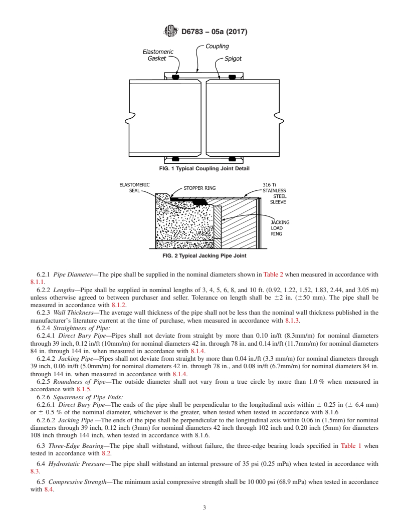
manufacturer. Figs. 1 and 2 show typical couplings.
5.2.2 Gaskets—Elastomeric gaskets used with this pipe shall conform to the requirements of Specification F477, except that
composition of the elastomer shall be as agreed upon between the purchaser and the supplier as being resistant to the intended
chemical environments.
6. Requirements
6.1 Workmanship—Each pipe shall be free from all defects, including indentations, cracks, foreign inclusions, and resin-starved
areas that, due to their nature, degree, or extent, detrimentally affect the strength and serviceability of the pipe. The pipe shall be
as uniform as commercially practicable in color, opacity, density, and other physical properties.
6.1.1 The inside surface of each pipe shall be free of bulges, dents, ridges, and other defects that result in a variation of inside
diameter of more than ⁄8 in. (3.2 mm) from that obtained on adjacent unaffected portions of the surface.
6.1.2 Joint sealing surfaces shall be free of dents, gouges, and other surface irregularities that will affect the integrity of the
joints.
6.2 Dimensions:
TABLE 1 Strength Classes for Polymer Concrete Pipe
D-Load
Strength
lb/ft/ft
Class
(kN/m/m)
I 1200 (57.5)
II 1500 (71.9)
III 2000 (95.8)
IV 3000 (143.8)
V 3750 (179.7)
D6783 − 05a (2017)
FIG. 1 Typical Coupling Joint Detail
FIG. 2 Typical Jacking Pipe Joint
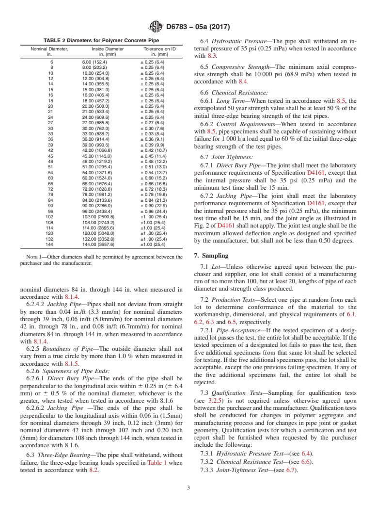
6.2.1 Pipe Diameter—The pipe shall be supplied in the nominal diameters shown in Table 2 when measured in accordance with
8.1.1.
6.2.2 Lengths—Pipe shall be supplied in nominal lengths of 3, 4, 5, 6, 8, and 10 ft. (0.92, 1.22, 1.52, 1.83, 2.44, and 3.05 m)
unless otherwise agreed to between purchaser and seller. Tolerance on length shall be 62 in. (650 mm). The pipe shall be
measured in accordance with 8.1.2.
6.2.3 Wall Thickness—The average wall thickness of the pipe shall not be less than the nominal wall thickness published in the
manufacturer’s literature current at the time of purchase, when measured in accordance with 8.1.3.
6.2.4 Straightness of Pipe:
6.2.4.1 Direct Bury Pipe—Pipes shall not deviate from straight by more than 0.10 in/ft (8.3mm/m) for nominal diameters
through 39 inch, 0.12 in/ft (10mm/m) for nominal diameters 42 in. through 78 in. and 0.14 in/ft (11.7mm/m) for nominal diameters
84 in. through 144 in. when measured in accordance with 8.1.4.
6.2.4.2 Jacking Pipe—Pipes shall not deviate from straight by more than 0.04 in./ft (3.3 mm/m) for nominal diameters through
39 inch, 0.06 in/ft (5.0mm/m) for nominal diameters 42 in. through 78 in., and 0.08 in/ft (6.7mm/m) for nominal diameters 84 in.
through 144 in. when measured in accordance with 8.1.4.
6.2.5 Roundness of Pipe—The outside diameter shall not vary from a true circle by more than 1.0 % when measured in
accordance with 8.1.5.
6.2.6 Squareness of Pipe Ends:
6.2.6.1 Direct Bury Pipe—The ends of the pipe shall be perpendicular to the longitudinal axis within 6 0.25 in (6 6.4 mm)
or 6 0.5 % of the nominal diameter, whichever is the greater, when tested when tested in accordance with 8.1.6
6.2.6.2 Jacking Pipe —The ends of the pipe shall be perpendicular to the longitudinal axis within 0.06 in (1.5mm) for nominal
diameters through 39 inch, 0.12 inch (3mm) for nominal diameters 42 inch through 102 inch and 0.20 inch (5mm) for diameters
108 inch through 144 inch, when tested in accordance with 8.1.6.
6.3 Three-Edge Bearing—The pipe shall withstand, without failure, the three-edge bearing loads specified in Table 1 when
tested in accordance with 8.2.
6.4 Hydrostatic Pressure—The pipe shall withstand an internal pressure of 35 psi (0.25 mPa) when tested in accordance with
8.3.
6.5 Compressive Strength—The minimum axial compressive strength shall be 10 000 psi (68.9 mPa) when tested in accordance
with 8.4.
D6783 − 05a (2017)
TABLE 2 Diameters for Polymer Concrete Pipe
Nominal Diameter, Inside Diameter Tolerance on ID
in. in. (mm) in. (mm)
6 6.00 (152.4) ± 0.25 (6.4)
8 8.00 (203.2) ± 0.25 (6.4)
10 10.00 (254.0) ± 0.25 (6.4)
12 12.00 (304.8) ± 0.25 (6.4)
14 14.00 (355.6) ± 0.25 (6.4)
15 15.00 (381.0) ± 0.25 (6.4)
16 16.00 (406.4) ± 0.25 (6.4)
18 18.00 (457.2) ± 0.25 (6.4)
20 20.00 (508.0) ± 0.25 (6.4)
21 21.00 (533.4) ± 0.25 (6.4)
24 24.00 (609.6) ± 0.25 (6.4)
27 27.00 (685.8) ± 0.27 (6.4)
30 30.00 (762.0) ± 0.30 (7.6)
33 33.00 (838.2) ± 0.33 (8.4)
36 36.00 (914.4) ± 0.36 (9.1)
39 39.00 (990.6) ± 0.39 (9.9)
42 42.00 (1066.8) ± 0.42 (10.7)
45 45.00 (1143.0) ± 0.45 (11.4)
48 48.00 (1219.2) ± 0.48 (12.2)
51 51.00 (1295.4) ± 0.51 (13.0)
54 54.00 (1371.6) ± 0.54 (13.7)
60 60.00 (1524.0) ± 0.60 (15.2)
66 66.00 (1676.4) ± 0.66 (16.8)
72 72.00 (1828.8) ± 0.72 (18.3)
78 78.00 (1981.2) ± 0.78 (19.8)
84 84.00 (2133.6) ± 0.84 (21.3)
90 90.00 (2286.0) ± 0.90 (22.9)
96 96.00 (2438.4) ± 0.96 (24.4)
102 102.00 (2590.8) ±1 .00 (25.4)
108 108.00 (2743.2) ±1.00 (25.4)
114 114.00 (2895.6) ±1.00 (25.4)
120 120.00 (3048.0) ±1 .00 (25.4)
132 132.00 (3352.8) ±1 .00 (25.4)
144 144.00 (3657.6) ±1.00 (25.4)
6.6 Chemical Resistance:
6.6.1 Long Term—When tested in accordance with 8.5, the extrapolated 50 year strength value shall be at least 50 % of the
initial three-edge bearing strength of the test pipes.
6.6.2 Control Requirements—When tested in accordance with 8.5, pipe specimens shall be capable of sustaining without failure
for 1 000 h a load equal to 60 % of the initial three-edge bearing strength of the test pipes.
6.7 Joint Tightness:
6.7.1 Direct Bury Pipe—The joint shall meet the laboratory performance requirements of Specification D4161, except that the
internal pressure shall be 35 psi (0.25 mPa) and the minimum test time shall be 15 min.
6.7.2 Jacking Pipe—The joint shall meet the laboratory performance requirements of Specification D4161, except that the
internal pressure shall be 35 psi (0.25 mPa), the minimum test time shall be 15 min, and the joint angle as illustrated in Fig. 2 of
D4161 shall not apply. The joint test angle shall be the maximum allowed deflection angle as designed and specified by the
manufacturer, but shall not be less than 0.50 degrees.
7. Sampling
7.1 Lot—Unless otherwise agreed upon between the purchaser and supplier, one lot shall consist of a manufacturing run of no
more than 100, but at least 20, lengths of pipe of each diameter and strength class produced.
7.2 Production Tests—Select one pipe at random from each lot to determine conformance of the material to the workmanship,
dimensional, and physical requirements of 6.1, 6.2, 6.3 and 6.5, respectively.
7.2.1 Pipe Acceptance—If the tested specimen of a designated lot passes the test, the entire lot shall be acceptable. If the tested
specimen of a designated lot fails to pass the test, then five additional specimens from that same lot shall be selected for testing.
If the five additional specimens pass, the lot shall be acceptable. except the one previous failing specimen. If any of the five
additional specimens fail, the entire lot shall be rejected.
7.3 Qualification Tests—Sampling for qualification tests (see 3.2.5) is not required unless otherwise agreed upon between the
purchaser and the manufacturer. Qualification tests shall be conducted for changes in polymer aggregate and manufacturing process
and for changes in pipe joint or gasket geometry. Qualification tests for which a certification and test report shall be furnished when
requested by the purchaser include the following:
7.3.1 Hydrostatic Pressure Test—(see 6.4).
D6783 − 05a (2017)
NOTE 1—Other diameters shall be permitted by agreement between the
purchaser and the manufacturer.
7.3.2 Chemical Resistance Test—(see 6.6).
7.3.3 Joint-Tightness Test—(se
...
Questions, Comments and Discussion
Ask us and Technical Secretary will try to provide an answer. You can facilitate discussion about the standard in here.