


ASTM E1084-86(2015)
(Test Method)Standard Test Method for Solar Transmittance (Terrestrial) of Sheet Materials Using Sunlight
Standard Test Method for Solar Transmittance (Terrestrial) of Sheet Materials Using Sunlight
SIGNIFICANCE AND USE
4.1 Solar transmittance is an important factor in the admission of energy through fenestration, collector glazing, and protective envelopes. This test method provides a means of measuring this factor under fixed conditions. While the data may be of assistance to designers in the selection and specification of glazing materials, the solar transmittance is not sufficient to define the rate of net heat transfer without information on other important factors.
4.2 This test method has been found practical for both transparent and translucent materials, as well as for those with transmittance reduced by highly reflective coatings. This test method is particularly applicable to the measurement of transmittance of inhomogeneous, fiber reinforced, patterned, or corrugated materials since the transmittance is averaged over a large area.
4.3 This test method may be used to measure transmittance of glazing materials at angles up to 60° off normal incidence.
Note 1: A technique similar to the one described but using a pyrheliometer has been used for the measurement of specular solar reflectance; however, there is insufficient experience with this technique for standardization at present.
SCOPE
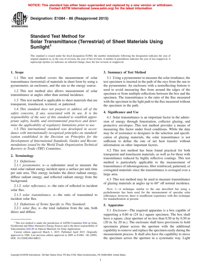
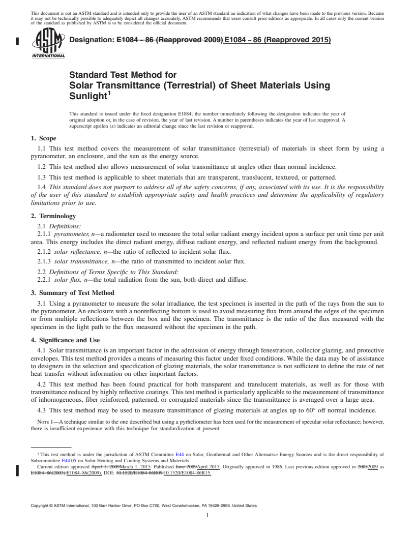
1.1 This test method covers the measurement of solar transmittance (terrestrial) of materials in sheet form by using a pyranometer, an enclosure, and the sun as the energy source.
1.2 This test method also allows measurement of solar transmittance at angles other than normal incidence.
1.3 This test method is applicable to sheet materials that are transparent, translucent, textured, or patterned.
1.4 This standard does not purport to address all of the safety concerns, if any, associated with its use. It is the responsibility of the user of this standard to establish appropriate safety and health practices and determine the applicability of regulatory limitations prior to use.
General Information
Buy Standard
Standards Content (Sample)
NOTICE: This standard has either been superseded and replaced by a new version or withdrawn.
Contact ASTM International (www.astm.org) for the latest information
Designation: E1084 − 86 (Reapproved 2015)
Standard Test Method for
Solar Transmittance (Terrestrial) of Sheet Materials Using
Sunlight
This standard is issued under the fixed designation E1084; the number immediately following the designation indicates the year of
original adoption or, in the case of revision, the year of last revision. A number in parentheses indicates the year of last reapproval. A
superscript epsilon (´) indicates an editorial change since the last revision or reapproval.
1. Scope 3. Summary of Test Method
1.1 This test method covers the measurement of solar 3.1 Using a pyranometer to measure the solar irradiance, the
transmittance (terrestrial) of materials in sheet form by using a test specimen is inserted in the path of the rays from the sun to
pyranometer, an enclosure, and the sun as the energy source. the pyranometer. An enclosure with a nonreflecting bottom is
used to avoid measuring flux from around the edges of the
1.2 This test method also allows measurement of solar
specimen or from multiple reflections between the box and the
transmittance at angles other than normal incidence.
specimen. The transmittance is the ratio of the flux measured
1.3 This test method is applicable to sheet materials that are
with the specimen in the light path to the flux measured without
transparent, translucent, textured, or patterned.
the specimen in the path.
1.4 This standard does not purport to address all of the
4. Significance and Use
safety concerns, if any, associated with its use. It is the
responsibility of the user of this standard to establish appro-
4.1 Solar transmittance is an important factor in the admis-
priate safety, health, and environmental practices and deter-
sion of energy through fenestration, collector glazing, and
mine the applicability of regulatory limitations prior to use.
protective envelopes. This test method provides a means of
1.5 This international standard was developed in accor-
measuring this factor under fixed conditions. While the data
dance with internationally recognized principles on standard-
may be of assistance to designers in the selection and specifi-
ization established in the Decision on Principles for the cation of glazing materials, the solar transmittance is not
Development of International Standards, Guides and Recom-
sufficient to define the rate of net heat transfer without
mendations issued by the World Trade Organization Technical information on other important factors.
Barriers to Trade (TBT) Committee.
4.2 This test method has been found practical for both
transparent and translucent materials, as well as for those with
2. Terminology
transmittance reduced by highly reflective coatings. This test
2.1 Definitions:
method is particularly applicable to the measurement of
2.1.1 pyranometer, n—a radiometer used to measure the
transmittance of inhomogeneous, fiber reinforced, patterned, or
total solar radiant energy incident upon a surface per unit time
corrugated materials since the transmittance is averaged over a
per unit area. This energy includes the direct radiant energy,
large area.
diffuse radiant energy, and reflected radiant energy from the
4.3 This test method may be used to measure transmittance
background.
of glazing materials at angles up to 60° off normal incidence.
2.1.2 solar reflectance, n—the ratio of reflected to incident
NOTE 1—A technique similar to the one described but using a
solar flux.
pyrheliometer has been used for the measurement of specular solar
2.1.3 solar transmittance, n—the ratio of transmitted to
reflectance; however, there is insufficient experience with this technique
incident solar flux.
for standardization at present.
2.2 Definitions of Terms Specific to This Standard:
5. Apparatus
2.2.1 solar flux, n—the total radiation from the sun, both
5.1 Enclosure—The required apparatus is a box capable of
direct and diffuse.
supporting a 0.60 m (24 in.) square specimen. The box shall
have a square, clear aperture of no less than 0.50 m by 0.50 m
(20 in. by 20 in.). The enclosure shall have provisions to hold
This test method is under the jurisdiction of ASTM Committee E44 on Solar,
Geothermal and Other Alternative Energy Sources and is the direct responsibility of
specimens planar across the aperture with the additional
Subcommittee E44.20 on Optical Materials for Solar Applications.
capability to remove and replace the specimen easily during the
Current edition approved March 1, 2015. Published April 2015. Originally
measurement process. It shall also have the capability to move
approved in 1986. Last previous edition approved in 2009 as E1084 – 86 (2009).
DOI: 10.1520/E1084-86R15. the specimen across the aperture in a systematic way. Light
Copyright © ASTM International, 100 Barr Harbor Drive, PO Box C700, West Conshohocken, PA 19428-2959. United States
E1084 − 86 (2015)
NOTE 2—Mirrors having the necessary specular reflectance are bright
baffled air vents at the top and bottom of the enclosure are
anodized aluminum lighting sheet, aluminized polymer films, and con-
recommended to aid cooling of all components when a
ventionally mirrored glass. For highly diffusing materials, a box with the
specimen is in place. The inside of the box shall have side walls
specified aperture and blackened side walls, the test method could
covered with mirrors having specular, solar reflectance greater
underestimate the transmittance by up to 0.03. Using highly reflecting side
than 0.85 that extend from the opening down to the plane of the
walls on the interior of the enclosure reduces this error for such materials
sensor element. The rest of the inside of the box shall be
to less than 0.01 transmittance unit. For highly specular materials, this
error is negligible.
blackened so that its solar reflectance is less than 0.10. A
typical unit is shown in Fig. 1. NOTE 3—For an enclosure with a highly reflecting bottom, the
(A) Specular mirror, 500 × 50 mm. (J) Standard 2 × 4 in. wood framing, 75 mm long (bottom to center of hole)
(B) Nonreflecting, black bottom. Nontransmitting louvers or multiple layers of grill (K) Rectangular, ⁄4 in. plywood, 500 × 75 mm.
cloth that allow air circulation into the enclosure are preferable.
(C) Pyranometer (L) ⁄2 × 2 in. carriage bolt with wing and washer.
(D) Support shelf for pyranometer. The height of the shelf will depend on the (M) ⁄4 in. iron pipe.
pyranometer used.
(E) Semicircular disk 538 mm diameter out of ⁄4 in plywood. (N) U-bolts.
(F) Semicircular tracker with scale (P) Primary tracking axis, aligned parallel to earth’s axis of rotation. The axis shall
make an angle with the vertical equal to the local latitude and point toward the
North Star.
(G) Lip of flange turned up to 20 mm to help support specimens (Q) C-clamp attached to arm to lock equatorial angle during measurements.
(H) 50 mm flange bent out of sheet metal or cut from wood. Top surface is (R) Vertical support post approximately 1 m long. Made from standard 2 × 6 ft
painted back to prevent light entering enclosure due to multiple reflections from lumber.
around the specimen edges.
NOTE 1—This apparatus consisting of enclosure, detector, and equatorial mount has been found acceptable for measuring solar transmittance of sheet
materials. The majority of the pieces are cut from standard 2.4, 2 by 6, and ⁄4 in. plywood construction materials.
FIG. 1 Apparatus Consisting of Enclosure, Detector, and Equatorial Mount
E1084 − 86 (2015)
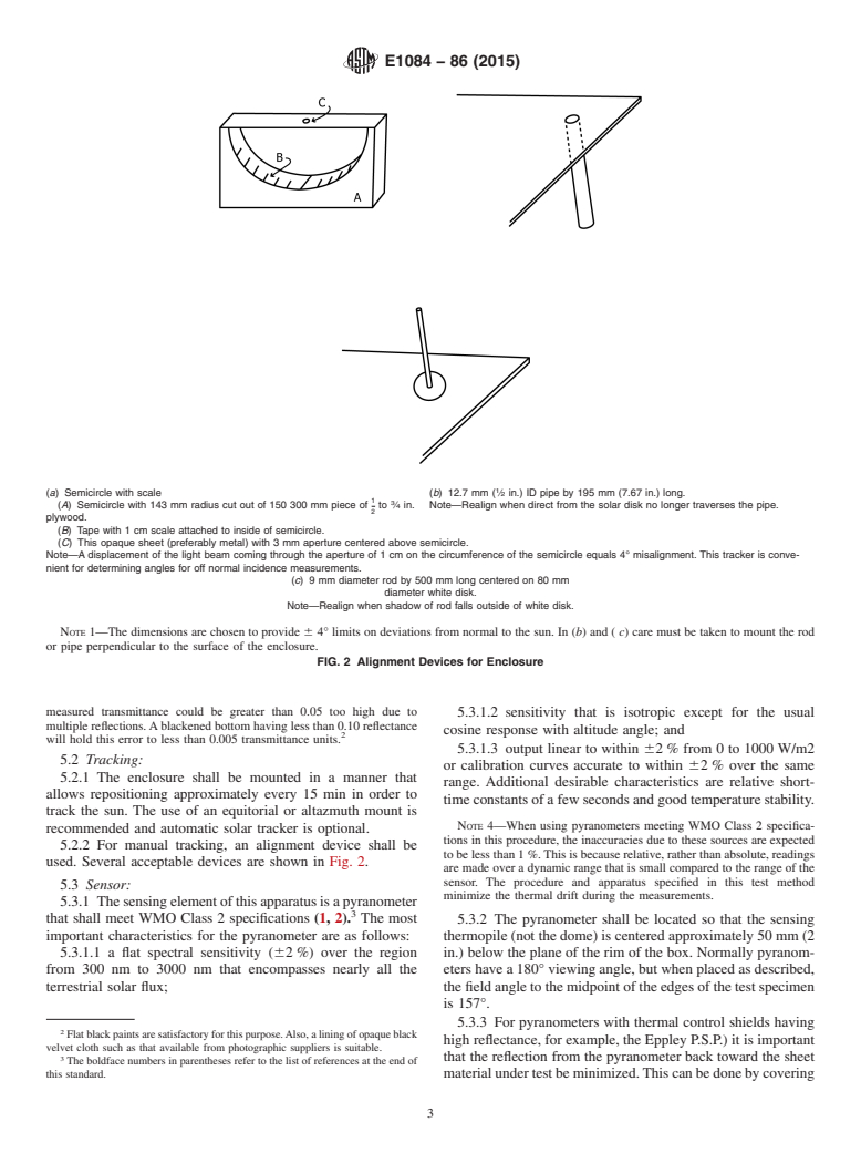
(a) Semicircle with scale (b) 12.7 mm ( ⁄2 in.) ID pipe by 195 mm (7.67 in.) long.
(A) Semicircle with 143 mm radius cut out of 150 300 mm piece of to ⁄4 in. Note—Realign when direct from the solar disk no longer traverses the pipe.
plywood.
(B) Tape with 1 cm scale attached to inside of semicircle.
(C) This opaque sheet (preferably metal) with 3 mm aperture centered above semicircle.
Note—A displacement of the light beam coming through the aperture of 1 cm on the circumference of the semicircle equals 4° misalignment. This tracker is conve-
nient for determining angles for off normal incidence measurements.
(c) 9 mm diameter rod by 500 mm long centered on 80 mm
diameter white disk.
Note—Realign when shadow of rod falls outside of white disk.
NOTE 1—The dimensions are chosen to provide 6 4° limits on deviations from normal to the sun. In (b) and ( c) care must be taken to mount the rod
or pipe perpendicular to the surface of the enclosure.
FIG. 2 Alignment Devices for Enclosure
measured transmittance could be greater than 0.05 too high due to
5.3.1.2 sensitivity that is isotropic except for the usual
multiple reflections. A blackened bottom having less than 0.10 reflectance
cosine response with altitude angle; and
will hold this error to less than 0.005 transmittance units.
5.3.1.3 output linear to within 62 % from 0 to 1000 W/m2
5.2 Tracking:
or calibration curves accurate to within 62 % over the same
5.2.1 The enclosure shall be mounted in a manner that
range. Additional desirable characteristics are relative short-
allows repositioning approximately every 15 min in order to
time constants of a few seconds and good temperature stability.
track the sun. The use of an equitorial or altazmuth mount is
NOTE 4—When using pyranometers meeting WMO Class 2 specifica-
recommended and automatic solar tracker is optional.
tions in this procedure, the inaccuracies due to these sources are expected
5.2.2 For manual tracking, an alignment device shall be
to be less than 1 %. This is because relative, rather than absolute, readings
used. Several acceptable devices are shown in Fig. 2.
are made over a dynamic range that is small compared to the range of the
sensor. The procedure and apparatus specified in this test method
5.3 Sensor:
minimize the thermal drift during the measurements.
5.3.1 The sensing element of this apparatus is a pyranometer
that shall meet WMO Class 2 specifications (1, 2). The most 5.3.2 The pyranometer shall be located so that the sensing
important characteristics for the pyranometer are as follows: thermopile (not the dome) is centered approximately 50 mm (2
5.3.1.1 a flat spectral sensitivity (62 %) over the region in.) below the plane of the rim of the box. Normally pyranom-
from 300 nm to 3000 nm that encompasses nearly all the eters have a 180° viewing angle, but when placed as described,
terrestrial solar flux; the field angle to the midpoint of the edges of the test specimen
is 157°.
5.3.3 For pyranometers with thermal control shields having
Flat black paints are satisfactory for this purpose. Also, a lining of opaque black
high reflectance, for example, the Eppley P.S.P.) it is important
velvet cloth such as that available from photographic suppliers is suitable.
3 that the reflection from the pyranomet
...
This document is not an ASTM standard and is intended only to provide the user of an ASTM standard an indication of what changes have been made to the previous version. Because
it may not be technically possible to adequately depict all changes accurately, ASTM recommends that users consult prior editions as appropriate. In all cases only the current version
of the standard as published by ASTM is to be considered the official document.
Designation: E1084 − 86 (Reapproved 2009) E1084 − 86 (Reapproved 2015)
Standard Test Method for
Solar Transmittance (Terrestrial) of Sheet Materials Using
Sunlight
This standard is issued under the fixed designation E1084; the number immediately following the designation indicates the year of
original adoption or, in the case of revision, the year of last revision. A number in parentheses indicates the year of last reapproval. A
superscript epsilon (´) indicates an editorial change since the last revision or reapproval.
1. Scope
1.1 This test method covers the measurement of solar transmittance (terrestrial) of materials in sheet form by using a
pyranometer, an enclosure, and the sun as the energy source.
1.2 This test method also allows measurement of solar transmittance at angles other than normal incidence.
1.3 This test method is applicable to sheet materials that are transparent, translucent, textured, or patterned.
1.4 This standard does not purport to address all of the safety concerns, if any, associated with its use. It is the responsibility
of the user of this standard to establish appropriate safety and health practices and determine the applicability of regulatory
limitations prior to use.
2. Terminology
2.1 Definitions:
2.1.1 pyranometer, n—a radiometer used to measure the total solar radiant energy incident upon a surface per unit time per unit
area. This energy includes the direct radiant energy, diffuse radiant energy, and reflected radiant energy from the background.
2.1.2 solar reflectance, n—the ratio of reflected to incident solar flux.
2.1.3 solar transmittance, n—the ratio of transmitted to incident solar flux.
2.2 Definitions of Terms Specific to This Standard:
2.2.1 solar flux, n—the total radiation from the sun, both direct and diffuse.
3. Summary of Test Method
3.1 Using a pyranometer to measure the solar irradiance, the test specimen is inserted in the path of the rays from the sun to
the pyranometer. An enclosure with a nonreflecting bottom is used to avoid measuring flux from around the edges of the specimen
or from multiple reflections between the box and the specimen. The transmittance is the ratio of the flux measured with the
specimen in the light path to the flux measured without the specimen in the path.
4. Significance and Use
4.1 Solar transmittance is an important factor in the admission of energy through fenestration, collector glazing, and protective
envelopes. This test method provides a means of measuring this factor under fixed conditions. While the data may be of assistance
to designers in the selection and specification of glazing materials, the solar transmittance is not sufficient to define the rate of net
heat transfer without information on other important factors.
4.2 This test method has been found practical for both transparent and translucent materials, as well as for those with
transmittance reduced by highly reflective coatings. This test method is particularly applicable to the measurement of transmittance
of inhomogeneous, fiber reinforced, patterned, or corrugated materials since the transmittance is averaged over a large area.
4.3 This test method may be used to measure transmittance of glazing materials at angles up to 60° off normal incidence.
NOTE 1—A technique similar to the one described but using a pyrheliometer has been used for the measurement of specular solar reflectance; however,
there is insufficient experience with this technique for standardization at present.
This test method is under the jurisdiction of ASTM Committee E44 on Solar, Geothermal and Other Alternative Energy Sources and is the direct responsibility of
Subcommittee E44.05 on Solar Heating and Cooling Systems and Materials.
Current edition approved April 1, 2009March 1, 2015. Published June 2009April 2015. Originally approved in 1986. Last previous edition approved in 20032009 as
E1084–86(2003).E1084–86(2009). DOI: 10.1520/E1084-86R09.10.1520/E1084-86R15.
Copyright © ASTM International, 100 Barr Harbor Drive, PO Box C700, West Conshohocken, PA 19428-2959. United States
E1084 − 86 (2015)
5. Apparatus
5.1 Enclosure—The required apparatus is a box capable of supporting a 0.60 m (24 in.) square specimen. The box shall have
a square, clear aperture of no less than 0.50 m by 0.50 m (20 in. by 20 in.). The enclosure shall have provisions to hold specimens
planar across the aperture with the additional capability to remove and replace the specimen easily during the measurement
process. It shall also have the capability to move the specimen across the aperture in a systematic way. Light baffled air vents at
the top and bottom of the enclosure are recommended to aid cooling of all components when a specimen is in place. The inside
of the box shall have side walls covered with mirrors having specular, solar reflectance greater than 0.85 that extend from the
opening down to the plane of the sensor element. The rest of the inside of the box shall be blackened so that its solar reflectance
is less than 0.10. A typical unit is shown in Fig. 1.
(A) Specular mirror, 500 × 50 mm. (J) Standard 2 × 4 in. wood framing, 75 mm long (bottom to center of hole)
(B) Nonreflecting, black bottom. Nontransmitting louvers or multiple layers of grill (K) Rectangular, ⁄4 in. plywood, 500 × 75 mm.
cloth that allow air circulation into the enclosure are preferable.
(C) Pyranometer (L) ⁄2 × 2 in. carriage bolt with wing and washer.
(D) Support shelf for pyranometer. The height of the shelf will depend on the (M) ⁄4 in. iron pipe.
pyranometer used.
(E) Semicircular disk 538 mm diameter out of ⁄4 in plywood. (N) U-bolts.
(F) Semicircular tracker with scale (P) Primary tracking axis, aligned parallel to earth’s axis of rotation. The axis shall
make an angle with the vertical equal to the local latitude and point toward the
North Star.
(G) Lip of flange turned up to 20 mm to help support specimens (Q) C-clamp attached to arm to lock equatorial angle during measurements.
(H) 50 mm flange bent out of sheet metal or cut from wood. Top surface is (R) Vertical support post approximately 1 m long. Made from standard 2 × 6 ft
painted back to prevent light entering enclosure due to multiple reflections from lumber.
around the specimen edges.
NOTE 1—This apparatus consisting of enclosure, detector, and equatorial mount has been found acceptable for measuring solar transmittance of sheet
materials. The majority of the pieces are cut from standard 2.4, 2 by 6, and ⁄4 in. plywood construction materials.
FIG. 1 Apparatus Consisting of Enclosure, Detector, and Equatorial Mount
E1084 − 86 (2015)
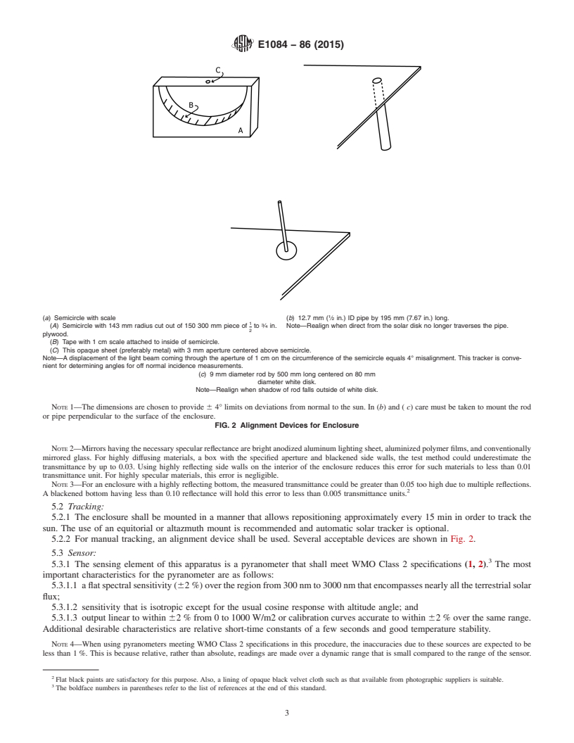
(a) Semicircle with scale (b) 12.7 mm ( ⁄2 in.) ID pipe by 195 mm (7.67 in.) long.
(A) Semicircle with 143 mm radius cut out of 150 300 mm piece of to ⁄4 in. Note—Realign when direct from the solar disk no longer traverses the pipe.
plywood.
(B) Tape with 1 cm scale attached to inside of semicircle.
(C) This opaque sheet (preferably metal) with 3 mm aperture centered above semicircle.
Note—A displacement of the light beam coming through the aperture of 1 cm on the circumference of the semicircle equals 4° misalignment. This tracker is conve-
nient for determining angles for off normal incidence measurements.
(c) 9 mm diameter rod by 500 mm long centered on 80 mm
diameter white disk.
Note—Realign when shadow of rod falls outside of white disk.
NOTE 1—The dimensions are chosen to provide 6 4° limits on deviations from normal to the sun. In (b) and ( c) care must be taken to mount the rod
or pipe perpendicular to the surface of the enclosure.
FIG. 2 Alignment Devices for Enclosure
NOTE 2—Mirrors having the necessary specular reflectance are bright anodized aluminum lighting sheet, aluminized polymer films, and conventionally
mirrored glass. For highly diffusing materials, a box with the specified aperture and blackened side walls, the test method could underestimate the
transmittance by up to 0.03. Using highly reflecting side walls on the interior of the enclosure reduces this error for such materials to less than 0.01
transmittance unit. For highly specular materials, this error is negligible.
NOTE 3—For an enclosure with a highly reflecting bottom, the measured transmittance could be greater than 0.05 too high due to multiple reflections.
A blackened bottom having less than 0.10 reflectance will hold this error to less than 0.005 transmittance units.
5.2 Tracking:
5.2.1 The enclosure shall be mounted in a manner that allows repositioning approximately every 15 min in order to track the
sun. The use of an equitorial or altazmuth mount is recommended and automatic solar tracker is optional.
5.2.2 For manual tracking, an alignment device shall be used. Several acceptable devices are shown in Fig. 2.
5.3 Sensor:
5.3.1 The sensing element of this apparatus is a pyranometer that shall meet WMO Class 2 specifications (1, 2). The most
important characteristics for the pyranometer are as follows:
5.3.1.1 a flat spectral sensitivity (62 %) over the region from 300 nm to 3000 nm that encompasses nearly all the terrestrial solar
flux;
5.3.1.2 sensitivity that is isotropic except for the usual cosine response with altitude angle; and
5.3.1.3 output linear to within 62 % from 0 to 1000 W/m2 or calibration curves accurate to within 62 % over the same range.
Additional desirable characteristics are relative short-time constants of a few seconds and good temperature stability.
NOTE 4—When using pyranometers meeting WMO Class 2 specifications in this procedure, the inaccuracies due to these sources are expected to be
less than 1 %. This is because relative, rather than absolute, readings are made over a dynamic range that is small compared to the range of the sensor.
Flat black paints are satisfactory for this purpose. Also, a lining of opaque black velvet cloth such as that available from photographic suppliers is suitable.
The boldface numbers in parentheses refer to the list of references at the end of this standard.
E1084 − 86 (2015)
The procedure and apparatus specified in this test method minimize the thermal drift during the measurements.
5.3.2 The pyranometer shall be located so that the sensing thermopile (not the dome) is centered approximately 50 mm (2 in.)
below the plane of the rim of the box. Normally pyranometers have a 180° viewing angle, but when placed as described, the field
angle to the midpoint of the edges of the
...
Questions, Comments and Discussion
Ask us and Technical Secretary will try to provide an answer. You can facilitate discussion about the standard in here.