


ASTM G174-04(2017)
(Test Method)Standard Test Method for Measuring Abrasion Resistance of Materials by Abrasive Loop Contact
Standard Test Method for Measuring Abrasion Resistance of Materials by Abrasive Loop Contact
SIGNIFICANCE AND USE
5.1 This test is useful for screening materials for use in tools that are subjected to abrasion from the material that is being machined, worked, or formed. It has been used to screen tool steels for punch press dies, hardfacings for earth-moving machinery, and wear coatings. This is simpler to build and use than those used in the Test Method G132 abrasion test which, like this test, uses a fixed abrasive counterface to abrade a test material.
5.2 The one-hour test is intended for metals and materials that are softer than hardened steel (67 HRC), but may be applied to harder materials (see 7.1.7).
SCOPE
1.1 This test method covers ranking rigid engineering materials for abrasion resistance in rubbing against aluminum oxide abrasive finishing tape. Though most solids can be tested, this test method addresses its use for metals, and coatings applied to metals.
1.2 The values stated in SI units are to be regarded as standard. No other units of measurement are included in this standard.
1.3 This standard does not purport to address all of the safety concerns, if any, associated with its use. It is the responsibility of the user of this standard to establish appropriate safety and health practices and determine the applicability of regulatory limitations prior to use.
1.4 This international standard was developed in accordance with internationally recognized principles on standardization established in the Decision on Principles for the Development of International Standards, Guides and Recommendations issued by the World Trade Organization Technical Barriers to Trade (TBT) Committee.
General Information
Buy Standard



Standards Content (Sample)
NOTICE: This standard has either been superseded and replaced by a new version or withdrawn.
Contact ASTM International (www.astm.org) for the latest information
Designation: G174 − 04 (Reapproved 2017)
Standard Test Method for
Measuring Abrasion Resistance of Materials by Abrasive
Loop Contact
This standard is issued under the fixed designation G174; the number immediately following the designation indicates the year of
original adoption or, in the case of revision, the year of last revision. A number in parentheses indicates the year of last reapproval. A
superscript epsilon (´) indicates an editorial change since the last revision or reapproval.
1. Scope sion Tests (Withdrawn 2016)
G132 Test Method for Pin Abrasion Testing
1.1 This test method covers ranking rigid engineering ma-
terials for abrasion resistance in rubbing against aluminum
3. Terminology
oxide abrasive finishing tape. Though most solids can be
3.1 Definitions:
tested, this test method addresses its use for metals, and
3.1.1 abrasive wear, n—wear due to hard particles or hard
coatings applied to metals.
protuberances forced against, and moving along, a solid
1.2 The values stated in SI units are to be regarded as
surface.
standard. No other units of measurement are included in this
3.2 Definitions of Terms Specific to This Standard:
standard.
3.2.1 abrasion, n—the process of abrasive wear.
1.3 This standard does not purport to address all of the
3.2.1.1 Discussion—Terminology G40 does not define abra-
safety concerns, if any, associated with its use. It is the
sion.
responsibility of the user of this standard to establish appro-
3.2.2 abrasion resistance, n—in tribology, the ability of a
priate safety and health practices and determine the applica-
material to resist damage or attrition by abrasion.
bility of regulatory limitations prior to use.
3.2.3 fixed abrasive tape, n—hard particles or grains bonded
1.4 This international standard was developed in accor-
(fixed) to one side of a flexible web with a resin or similar
dance with internationally recognized principles on standard-
binder. The particles can be of any hard material and vary in
ization established in the Decision on Principles for the
size. (This abrasive medium is also known as “finishing tape,”
Development of International Standards, Guides and Recom-
“microfinishing tape,” “microfinishing film,” or “finishing
mendations issued by the World Trade Organization Technical
film.”)
Barriers to Trade (TBT) Committee.
3.2.4 flexible web, n—plastic, paper, rubber, or other mate-
2. Referenced Documents
rial that is thin enough to conform to a 180° wrap around a
16-mm diameter cylinder under a tension of less than
2.1 ASTM Standards:
1.8 kg⁄cm width.
E177 Practice for Use of the Terms Precision and Bias in
ASTM Test Methods
4. Summary of Test Method
E178 Practice for Dealing With Outlying Observations
4.1 This test involves rubbing an abrasive tape loop initially
E691 Practice for Conducting an Interlaboratory Study to
in line-contact with a solid surface.The tape abrasion produces
Determine the Precision of a Test Method
a groove in the test surface, and the volume of material
G40 Terminology Relating to Wear and Erosion
removed in a designated amount of abrasive rubbing is
G117 Guide for Calculating and Reporting Measures of
measured by mass loss or by calculation from the groove
Precision Using Data from Interlaboratory Wear or Ero-
geometry. The continuous loop of abrasive is used for the
duration of the test and then discarded.Afresh loop is used for
each one-hour test.
This test method is under the jurisdiction of ASTM Committee G02 on Wear
and Erosion and is the direct responsibility of Subcommittee G02.30 on Abrasive 4.2 The wear volume produced in this test provides a
Wear.
measure of the ability of a surface to resist wear damage from
Current edition approved July 15, 2017. Published August 2017. Originally
abrasive substances. The smaller the wear volume in this test,
ɛ1
approved in 2003. Last previous edition approved in 2009 as G174 – 04 (2009) .
the better the abrasion resistance.
DOI: 10.1520/G0174-04R17.
For referenced ASTM standards, visit the ASTM website, www.astm.org, or
contact ASTM Customer Service at service@astm.org. For Annual Book of ASTM
Standards volume information, refer to the standard’s Document Summary page on The last approved version of this historical standard is referenced on
the ASTM website. www.astm.org.
Copyright © ASTM International, 100 Barr Harbor Drive, PO Box C700, West Conshohocken, PA 19428-2959. United States
G174 − 04 (2017)
FIG. 1 Schematic of Test Rig
4.3 The test was developed using 30 µm-mean diameter 7. Test Procedure
aluminum oxide abrasive on a 127 µm-thick polyester support,
7.1 Standard Test for Metals Softer than 67 HRC:
but other commercially available abrasive tapes could be used.
7.1.1 Specimen Preparation—The test surfaces (7.6 by
The test has also been used with webs such as paper that are
32 mm)shouldhaveagroundorlappedfinishwitharoughness
inherently abrasive to many materials.
less than 0.2 µm Ra. The surface lay shall be aligned with the
longaxisofthetestspecimen.Whentestingmoldedsurfacesor
5. Significance and Use
specific finishes, the test samples should have the finish of
5.1 Thistestisusefulforscreeningmaterialsforuseintools
interest on the test faces.
that are subjected to abrasion from the material that is being
7.1.2 Cleaning—Cleaning is not needed if the test surfaces
machined, worked, or formed. It has been used to screen tool
are untouched after the sample preparation and no lubricants,
steels for punch press dies, hardfacings for earth-moving
and so forth, were used in fabrication. If the surfaces are
machinery, and wear coatings. This is simpler to build and use
contaminated, clean in a solvent that will not leave a surface
than those used in the Test Method G132 abrasion test which,
film or degrade the properties of the test surface (acetone is
like this test, uses a fixed abrasive counterface to abrade a test
suitable for most metals).
material.
7.1.3 Weighing—If mass change is going to be used as the
5.2 The one-hour test is intended for metals and materials
test metric, weigh the test specimen to the nearest tenth of a
that are softer than hardened steel (67 HRC), but may be
milligram and record this as the initial weight.
applied to harder materials (see 7.1.7).
7.1.4 Sample Attachment—Affix the test sample to loading
arm and the 200 g-loading mass over the line where the
6. Apparatus
specimen has tangential contact with the tape.
6.1 The test apparatus used in interlaboratory tests is illus-
7.1.5 Belt Tensioning—Tension the abrasive belt over the
trated in Fig. 1.A132-cm long by 25.4-mm wide abrasive tape
drive spindle and idler rollers by moving idler rollers. Check
is made into a continuous loop with a pressure sensitive
the loop for slip with a mark on the tape and spindle. Loops are
adhesive (PSA) butt splice (Fig. 2). The web is tensioned to
used only once for one hour.
form a triangle with the 16-mm diameter drive spindle at the
7.1.6 Check Systems Alignment—Tapered scars will result if
apex. The idler rolls can be of any diameter, but a convenient
the sample is not parallel to the drive spindle. Check alignment
size is about 50 mm radius with flanges to prevent lateral
by putting pressure sensing media on the spindle and bring the
movement of the tape. The test sample shall have the dimen-
specimen in contact with the spindle. The pressure-sensing
sions shown in Fig. 3. It is clamped or attached to the
medium must show line contact across the sample width. Thin
counterbalanced loading arm with PSAfoam. The loading arm
foils (less than 25 µm) can also be used to make sure that both
is pivoted on rolling element bearings.A200 g loading mass is
edgesofthetestsamplearecontactingthespindles.Putthefoil
attached to the pivot arm and centered directly over the line
betweenthespindleandtheedgeofthesampleandpullthefoil
contact between the specimen and drive spindle.
out. Repeat on the other side. Equal pull force on both sides
6.2 One idler roller must be adjustable to produce tape shows good alignment, and can be measured with a force
tensionsufficienttodrivethetapewithspindle-to-tapeslippage measuring device. Lock the aligned sample arm in place. Put
of less than 20 m in a one-hour test time. The drive spindle the loop on and tension it as in 7.1.5. Turn the tester on for 5
shall be 16 mm in diameter and have a total indicated run-out to 10 s and lift the sample arm and check for a uniform wear
of less than 20 µm at a rotational speed of 300 rpm. scar across the sample width.
G174 − 04 (2017)
1—8 mil-thick microfinishing film was used in interlaboratory tests. It was purchased at:
3M Corporation
Imperial Lapping Film 262L
Grade 30 MIC, Mineral A/O
Backing 5 mil Size 1 by 150 by 3 in.
2—Scotch Magic Tape (3M Corp.) was used in interlaboratory tests
3—3M Corp.
3M Center, Building 251-2A-08
St. Paul, MN 55144–1000 USA
NOTE 1—Some tapes may have a release agent on the back that must be removed by abrasion followed by solvent wipe.
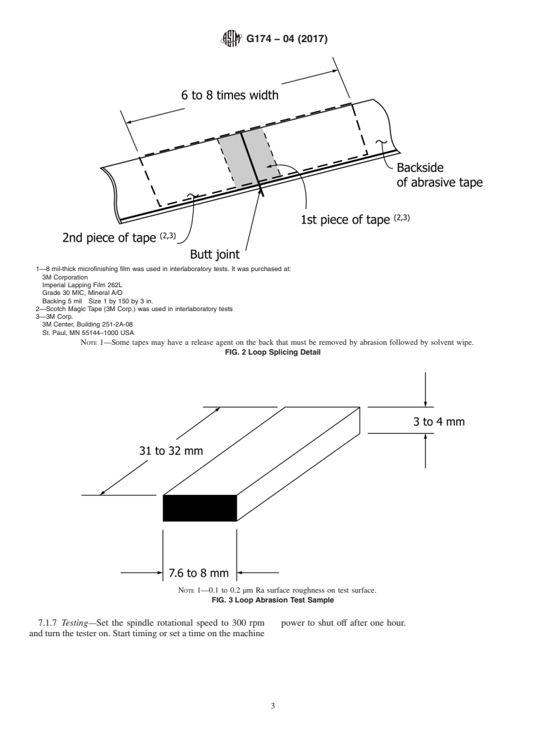
FIG. 2 Loop Splicing Detail
NOTE 1—0.1 to 0.2 µm Ra surface roughness on test surface.
FIG. 3 Loop Abrasion Test Sample
7.1.7 Testing—Set the spindle rotational speed to 300 rpm power to shut off after one hour.
and turn the tester on. Start timing or set a time on the machine
G174 − 04 (2017)
FIG. 4 Scar Measureme
...
This document is not an ASTM standard and is intended only to provide the user of an ASTM standard an indication of what changes have been made to the previous version. Because
it may not be technically possible to adequately depict all changes accurately, ASTM recommends that users consult prior editions as appropriate. In all cases only the current version
of the standard as published by ASTM is to be considered the official document.
´1
Designation: G174 − 04 (Reapproved 2009) G174 − 04 (Reapproved 2017)
Standard Test Method for
Measuring Abrasion Resistance of Materials by Abrasive
Loop Contact
This standard is issued under the fixed designation G174; the number immediately following the designation indicates the year of
original adoption or, in the case of revision, the year of last revision. A number in parentheses indicates the year of last reapproval. A
superscript epsilon (´) indicates an editorial change since the last revision or reapproval.
ε NOTE—Minor editorial changes were made throughout in May 2009.
1. Scope
1.1 This test method covers ranking rigid engineering materials for abrasion resistance in rubbing against aluminum oxide
abrasive finishing tape. Though most solids can be tested, this test method addresses its use for metals, and coatings applied to
metals.
1.2 The values stated in SI units are to be regarded as standard. No other units of measurement are included in this standard.
1.3 This standard does not purport to address all of the safety concerns, if any, associated with its use. It is the responsibility
of the user of this standard to establish appropriate safety and health practices and determine the applicability of regulatory
limitations prior to use.
1.4 This international standard was developed in accordance with internationally recognized principles on standardization
established in the Decision on Principles for the Development of International Standards, Guides and Recommendations issued
by the World Trade Organization Technical Barriers to Trade (TBT) Committee.
2. Referenced Documents
2.1 ASTM Standards:
E177 Practice for Use of the Terms Precision and Bias in ASTM Test Methods
E178 Practice for Dealing With Outlying Observations
E691 Practice for Conducting an Interlaboratory Study to Determine the Precision of a Test Method
G40 Terminology Relating to Wear and Erosion
G117 Guide for Calculating and Reporting Measures of Precision Using Data from Interlaboratory Wear or Erosion Tests
(Withdrawn 2016)
G132 Test Method for Pin Abrasion Testing
3. Terminology
3.1 Definitions:
3.1.1 abrasive wear, n—wear due to hard particles or hard protuberances forced against, and moving along, a solid surface.
3.2 Definitions of Terms Specific to This Standard:
3.2.1 abrasion, n—the process of abrasive wear.
This test method is under the jurisdiction of ASTM Committee G02 on Wear and Erosion and is the direct responsibility of Subcommittee G02.30 on Abrasive Wear.
Current edition approved May 1, 2009July 15, 2017. Published May 2009August 2017. Originally approved in 2003. Last previous edition approved in 20042009 as G174
ɛ1
– 04. 04 (2009) . DOI: 10.1520/G0174-04R09E01. 10.1520/G0174-04R17.
For referenced ASTM standards, visit the ASTM website, www.astm.org, or contact ASTM Customer Service at service@astm.org. For Annual Book of ASTM Standards
volume information, refer to the standard’s Document Summary page on the ASTM website.
The last approved version of this historical standard is referenced on www.astm.org.
3.2.1.1 Discussion—
Terminology G40 does not define abrasion.
3.2.2 abrasion resistance, n—in tribology, the ability of a material to resist damage or attrition by abrasion.
Copyright © ASTM International, 100 Barr Harbor Drive, PO Box C700, West Conshohocken, PA 19428-2959. United States
G174 − 04 (2017)
FIG. 1 Schematic of Test Rig
3.2.3 fixed abrasive tape, n—hard particles or grains bonded (fixed) to one side of a flexible web with a resin or similar binder.
The particles can be of any hard material and vary in size. (This abrasive medium is also known as “finishing tape,” “microfinishing
tape,” “microfinishing film,” or “finishing film.”)
3.2.4 flexible web, n—plastic, paper, rubber, or other material that is thin enough to conform to a 180° wrap around a 16-mm
diameter cylinder under a tension of less than 1.8 kg ⁄cm width.
4. Summary of Test Method
4.1 This test involves rubbing an abrasive tape loop initially in line-contact with a solid surface. The tape abrasion produces a
groove in the test surface, and the volume of material removed in a designated amount of abrasive rubbing is measured by mass
loss or by calculation from the groove geometry. The continuous loop of abrasive is used for the duration of the test and then
discarded. A fresh loop is used for each one-hour test.
4.2 The wear volume produced in this test provides a measure of the ability of a surface to resist wear damage from abrasive
substances. The smaller the wear volume in this test, the better the abrasion resistance.
4.3 The test was developed using 30 μm-mean diameter aluminum oxide abrasive on a 127 μm-thick polyester support, but other
commercially available abrasive tapes could be used. The test has also been used with webs such as paper that are inherently
abrasive to many materials.
5. Significance and Use
5.1 This test is useful for screening materials for use in tools that are subjected to abrasion from the material that is being
machined, worked, or formed. It has been used to screen tool steels for punch press dies, hardfacings for earth-moving machinery,
and wear coatings. This is simpler to build and use than those used in the Test Method G132 abrasion test which, like this test,
uses a fixed abrasive counterface to abrade a test material.
5.2 The one-hour test is intended for metals and materials that are softer than hardened steel (67 HRC), but may be applied to
harder materials (see 7.1.7).
6. Apparatus
6.1 The test apparatus used in interlaboratory tests is illustrated in Fig. 1. A 132-cm long by 25.4-mm wide abrasive tape is made
into a continuous loop with a pressure sensitive adhesive (PSA) butt splice (Fig. 2). The web is tensioned to form a triangle with
the 16-mm diameter drive spindle at the apex. The idler rolls can be of any diameter, but a convenient size is about 50 mm radius
with flanges to prevent lateral movement of the tape. The test sample shall have the dimensions shown in Fig. 3. It is clamped or
attached to the counterbalanced loading arm with PSA foam. The loading arm is pivoted on rolling element bearings. A200A 200
g loading mass is attached to the pivot arm and centered directly over the line contact between the specimen and drive spindle.
6.2 One idler roller must be adjustable to produce tape tension sufficient to drive the tape with spindle-to-tape slippage of less
than 20 m in a one-hour test time. The drive spindle shall be 16 mm in diameter and have a total indicated run-out of less than
20 μm at a rotational speed of 300 rpm.
7. Test Procedure
7.1 Standard Test for Metals Softer than 67 HRC:
G174 − 04 (2017)
1—8 mil-thick microfinishing film was used in interlaboratory tests. It was purchased at:
3M Corporation
Imperial Lapping Film 262L
Grade 30 MIC, Mineral A/O
Backing 5 mil Size 1 by 150 by 3 in.
2—Scotch Magic Tape (3M Corp.) was used in interlaboratory tests
3—3M Corp.
3M Center, Building 251-2A-08
St. Paul, MN 55144–1000 USA
NOTE 1—Some tapes may have a release agent on the back that must be removed by abrasion followed by solvent wipe.
FIG. 2 Loop Splicing Detail
NOTE 1—0.1 to 0.2 μm Ra surface roughness on test surface.
FIG. 3 Loop Abrasion Test Sample
7.1.1 Specimen Preparation—The test surfaces (7.6 by 32 mm) should have a ground or lapped finish with a roughness less than
0.2 μm Ra. The surface lay shall be aligned with the long axis of the test specimen. When testing molded surfaces or specific
finishes, the test samples should have the finish of interest on the test faces.
7.1.2 Cleaning—Cleaning is not needed if the test surfaces are untouched after the sample preparation and no lubricants, and
so forth, were used in fabrication. If the surfaces are contaminated, clean in a solvent that will not leave a surface film or degrade
the properties of the test surface (acetone is suitable for most metals).
G174 − 04 (2017)
7.1.3 Weighing—If mass change is going to be used as the test metric, weigh the test specimen to the nearest tenth of a milligram
and record this as the initial weight.
7.1.4 Sample Attachment—Affix the test sample to loading arm and the 200 g-loading mass over the line where the specimen
has tangential contact with the tape.
7.1.5 Belt Tensioning—Tension the abrasive belt over the drive spindle and idler rollers by moving idler rollers. Check the loop
for slip with a mark on the tape and spindle. Loops are used only once for one hour.
7.1.6 Check Systems Alignment—Tapered scars will result if the sample is not parallel to the drive spindle. Check alignment by
putting pressure sensing media on the spindle and bring the specimen in contact with the spindle. The pressure-sensing medium
must show line contact across the sample width. Thin foils (less than 25 μm) can also be used to make sure that both edges of the
test sample are contacting the spindles. Put the foil between the spindle and the edge of the sample and pull the foil out. Repeat
on the other side. Equal pull force on both sides shows good alignment, and can be measured with a force measuring device. Lock
the aligned sample arm in place. Put the loop on and tension it as in 7.1.5. Turn the tester on for 5 to 10 s and lift the sample arm
and check for a uniform wear scar across the sample width.
7.1.7 Testi
...
Questions, Comments and Discussion
Ask us and Technical Secretary will try to provide an answer. You can facilitate discussion about the standard in here.