


ASTM D6011-96(2015)
(Test Method)Standard Test Method for Determining the Performance of a Sonic Anemometer/Thermometer
Standard Test Method for Determining the Performance of a Sonic Anemometer/Thermometer
SIGNIFICANCE AND USE
5.1 This test method provides a standard method for evaluating the performance of sonic anemometer/thermometers that use inverse time solutions to measure wind velocity components and the speed of sound. It provides an unambiguous determination of instrument performance criteria. The test method is applicable to manufacturers for the purpose of describing the performance of their products, to instrumentation test facilities for the purpose of verifying instrument performance, and to users for specifying performance requirements. The acoustic pathlength procedure is also applicable for calibration purposes prior to data collection. Procedures for operating a sonic anemometer/thermometer are described in Practice D5527.
5.2 The sonic anemometer/thermometer array is assumed to have a sufficiently high structural rigidity and a sufficiently low coefficient of thermal expansion to maintain an internal alignment to within the manufacturer's specifications over its designed operating range. Consult with the manufacturer for an internal alignment verification procedure and verify the alignment before proceeding with this test method.
5.3 This test method is designed to characterize the performance of an array model or probe design. Transducer shadow data obtained from a single array is applicable for all instruments having the same array model or probe design. Some non-orthogonal arrays may not require specification of transducer shadow corrections or the velocity calibration range.
SCOPE
1.1 This test method covers the determination of the dynamic performance of a sonic anemometer/thermometer which employs the inverse time measurement technique for velocity or speed of sound, or both. Performance criteria include: (a) acceptance angle, (b) acoustic pathlength, (c) system delay, (d) system delay mismatch, (e) thermal stability range, (f) shadow correction, (g) velocity calibration range, and (h) velocity resolution.
1.2 The values stated in SI units are to be regarded as standard. No other units of measurement are included in this standard.
1.3 This standard does not purport to address all of the safety concerns, if any, associated with its use. It is the responsibility of the user of this standard to establish appropriate safety and health practices and determine the applicability of regulatory limitations prior to use.
General Information
Buy Standard
Standards Content (Sample)
NOTICE: This standard has either been superseded and replaced by a new version or withdrawn.
Contact ASTM International (www.astm.org) for the latest information
Designation: D6011 − 96 (Reapproved 2015)
Standard Test Method for
Determining the Performance of a Sonic Anemometer/
Thermometer
This standard is issued under the fixed designation D6011; the number immediately following the designation indicates the year of
original adoption or, in the case of revision, the year of last revision.Anumber in parentheses indicates the year of last reapproval.A
superscript epsilon (´) indicates an editorial change since the last revision or reapproval.
1. Scope 3.2.1 axial attenuation coeffıcient—aratioofthefreestream
windvelocity(asdefinedinawindtunnel)tovelocityalongan
1.1 This test method covers the determination of the dy-
acoustic propagation path (v /v ) (1).
t d
namicperformanceofasonicanemometer/thermometerwhich
3.2.2 critical Reynolds number (R )—the Reynolds number
employs the inverse time measurement technique for velocity
c
at which an abrupt decrease in an object’s drag coefficient
or speed of sound, or both. Performance criteria include: (a)
occurs (2).
acceptanceangle,(b)acousticpathlength,(c)systemdelay,(d)
3.2.2.1 Discussion—The transducer shadow corrections are
system delay mismatch, (e) thermal stability range, (f) shadow
no longer valid above the critical Reynolds number due to a
correction, (g) velocity calibration range, and (h) velocity
discontinuity in the axial attenuation coefficient.
resolution.
3.2.3 Reynolds number (R )—the ratio of inertial to viscous
1.2 The values stated in SI units are to be regarded as
e
forces on an object immersed in a flowing fluid based on the
standard. No other units of measurement are included in this
object’s characteristic dimension, the fluid velocity, and vis-
standard.
cosity.
1.3 This standard does not purport to address all of the
3.2.4 shadow correction (v /v )—the ratio of the true
safety concerns, if any, associated with its use. It is the dm d
along-axis velocity v , as measured in a wind tunnel or by
responsibility of the user of this standard to establish appro- dm
another accepted method, to the instrument along-axis wind
priate safety and health practices and determine the applica-
measurement v .
bility of regulatory limitations prior to use. d
3.2.4.1 Discussion—This correction compensates for flow
2. Referenced Documents
shadowing effects of transducers and their supporting struc-
tures. The correction can take the form of an equation (3) or a
2.1 ASTM Standards:
lookup table (4).
C384Test Method for Impedance andAbsorption ofAcous-
tical Materials by Impedance Tube Method 3.2.5 speed of sound (c, (m/s))—the propagation rate of an
adiabatic compression wave:
D1356Terminology Relating to Sampling and Analysis of
Atmospheres
0.5
c 5 ~γ]P/]ρ! (1)
s
D5527Practices for Measuring Surface Wind and Tempera-
where:
ture by Acoustic Means
IEEE/ASTM SI 10American National Standard for Metric
P = pressure
ρ = density,
Practice
γ = specific heat ratio, and
3. Terminology
s = isentropic (adiabatic) process (5).
3.1 Definitions—For definitions of terms related to this test
3.2.5.1 Discussion—The velocity of the compression wave
method, refer to Terminology D1356.
defined along each axis of a Cartesian coordinate system is the
3.2 Definitions of Terms Specific to This Standard:
sum of propagation speed c plus the motion of the gas along
that axis. In a perfect gas (6):
1 0.5
This test method is under the jurisdiction of ASTM Committee D22 on Air
c 5 γR*T/M (2)
~ !
Quality and is the direct responsibility of Subcommittee D22.11 on Meteorology.
Current edition approved April 1, 2015. Published April 2015. Originally The approximation for propagation in air is:
approved in 1996. Last previous edition approved in 2008 as D6011–96 (2008).
0.5 0.5
c 5 403 T 110.32 e/P 5 403 T (3)
@ ~ !# ~ !
DOI: 10.1520/D6011-96R15. air s
For referenced ASTM standards, visit the ASTM website, www.astm.org, or
contact ASTM Customer Service at service@astm.org. For Annual Book of ASTM
Standards volume information, refer to the standard’s Document Summary page on Theboldfacenumbersinparenthesesrefertothelistofreferencesattheendof
the ASTM website. this standard.
Copyright © ASTM International, 100 Barr Harbor Drive, PO Box C700, West Conshohocken, PA 19428-2959. United States
D6011 − 96 (2015)
3.2.6 system clock—the clock used for timing acoustic 3.2.11.2 Discussion—Proceduresinthistestmethodinclude
wavefront travel between a transducer pair. a test to determine whether separate determinations of δ t and
δt are needed, or whether an average δt can be used. The
3.2.7 system delay (δt, µs)—the time delay through the
relationship of transit time to speed of sound is:
transducer and electronic circuitry (7).
d 1 1
3.2.7.1 Discussion—Each path through every sonic array
2 2
c 5 1 1v (10)
F S DG
n
axis can have unique delay characteristics. Delay (on the order 2 t t
1 2
of 10 to 20 µs) can vary as a function of temperature and
and the inverse transit time solution for sonic tempera-
directionofsignaltravelthroughthetransducersandelectronic
ture in air is as follows (5):
circuitry.Theaveragesystemdelayforeachaxisinanacoustic
2 2 2
d 1 1 v
n
array is the average of the delays measured in each direction
T 5 1 1 (11)
S D F G
s
1612 t t 403
1 2
along the axis:
3.2.12 velocity calibration range (U to U , (m/s))—the
c s
δt 5 δt 1δt /2 (4)
~ !
1 2
range of velocity between creeping flow and the flow at which
3.2.8 system delay mismatch (δt, µs )—the absolute differ-
t
a critical Reynolds number is reached.
ence in microseconds between total transit times t in each
t
3.2.12.1 Discussion—The shadow correction is valid over a
direction (t , t ) through the system electronics and transduc-
t1 t2
rangeofvelocitieswherenodiscontinuitiesareobservedinthe
ers.
axial attenuation coefficient.
3.2.8.1 Discussion—Due principally to slight differences in
3.2.13 velocity resolution (δv, (m/s))—the largest change in
transducerperformance,thetotaltransittimeobtainedwiththe
an along-axis wind component that would cause no change in
signal originating at one transducer can differ from the total
the pulse arrival time count.
transit time obtained with the signal originating at its paired
transducer. The manufacturer should specify the system delay 3.2.13.1 Discussion—Velocity resolution defines the small-
mismatch tolerance. est resolvable wind velocity increment as determined from
systemclockrate.Forsomesystems,δvdefinedasthestandard
δt 5 t 2 t (5)
t ? t1 t2 ?
deviation of system dither can also be reported.
3.2.9 thermal stability range (°C)—a range of temperatures
3.3 Symbols:
over which the corrected velocity output in a zero wind
chamber remains at or below instrument resolution.
c = speed of sound, m/s,
3.2.9.1 Discussion—Thermal stability range defines a range
C = specific heat at constant pressure, J/(kg·K),
p
of temperatures over which there is no step change in system
C = specific heat at constant volume, J/(kg·K),
v
delay.
e = vapor pressure, Pa,
d = acoustic pathlength, m,
3.2.10 time resolution (∆t, µs)—resolution of the internal
f = compressibility factor, dimensionless,
clock used to measure time.
M = molecular weight of a gas, g/mol,
3.2.11 transit time (t, µs)—the time required for an acoustic
P = pressure, Pa,
wavefront to travel from the transducer of origin to the
R* = universal gas constant, 8.31436 J/(mol·K),
receiving transducer.
RH = relative humidity, %,
t = transit time, µs,
3.2.11.1 Discussion—Transit time (also known as time of
t = total transit time, µs,
flight) is determined by acoustic pathlength d, the speed of t
T = absolute temperature, K,
sound c, the velocity component along the acoustic propaga-
T = sonic absolute temperature, K,
s
tion path v , and cross-path velocity components) v (8):
d n
U = upper limit for creeping flow, m/s,
c
2 2 0.5 2 2 2
t 5 d c 2 v 6V / c 2 v 1v (6)
@~ ! # @ ~ !#
n d d n
U = critical Reynolds number velocity, m/s,
s
v = velocity component along acoustic propagation path,
d
The transit time difference between acoustic wavefront
m/s,
propagation in one direction (t , computed for+ v ) and
1 d
v = tunnel velocity component parallel to the array axis
dm
the other (t , computed for− v ) for each transducer pair
2 d
(v, cos θ), m/s,
t
determines the magnitude of a velocity component. The
v = velocitycomponentnormaltoanacousticpropagation
n
inverse transit time solution for the along-axis velocity is
path, m/s,
(9):
v = free stream wind velocity component (unaffected by
t
d 1 1
thepresenceofanobstaclesuchastheacousticarray),
v 5 2 (7)
F G
d
2 t t
1 2 m/s,
δt = system delay, µs,
The total transit times t and t , include the sum of
t1 t2
δt = system delay mismatch, µs,
t
actual transit times plus system delay through the electron-
∆t = clock pulse resolution, s,
ics and transducers in each direction along an acoustic
α = acceptance angle, degree,
path, δ and δ . System delay must be removed to calcu-
t1 t2
γ = specific heat ratio (C /C ), dimensionless,
p v
late v , that is:
d
δv = velocity resolution, m/s,
θ = array angle of attack, degree, and
t 5 t 2 δ (8)
1 t1 t1
ρ = gas density, kg/m .
t 5 t 2 δ (9)
2 t2 t2
D6011 − 96 (2015)
3.4 Units—Units of measurement are in accordance with
IEEE/ASTM SI 10.
4. Summary of Test Method
4.1 Acoustic pathlength, system delay, and system delay
mismatch are determined using the dual gas or zero wind
chamber method. The acoustic pathlength and system clock
rate are used to calculate the velocity resolution. Thermal
sensitivity range is defined using a zero wind chamber. The
axial attenuation coefficient, velocity calibration range, and
transducer shadow effects are defined in a wind tunnel. Wind
tunnel results are used to compute shadow corrections and to
define acceptance angles.
5. Significance and Use
5.1 This test method provides a standard method for evalu-
ating the performance of sonic anemometer/thermometers that
use inverse time solutions to measure wind velocity compo-
nents and the speed of sound. It provides an unambiguous
FIG. 1 Sonic Anemometer Array in a Zero Wind Chamber
determination of instrument performance criteria. The test
method is applicable to manufacturers for the purpose of
describing the performance of their products, to instrumenta-
tion test facilities for the purpose of verifying instrument
performance, and to users for specifying performance require-
ments.Theacousticpathlengthprocedureisalsoapplicablefor
calibration purposes prior to data collection. Procedures for
operating a sonic anemometer/thermometer are described in
Practices D5527.
5.2 Thesonicanemometer/thermometerarrayisassumedto
haveasufficientlyhighstructuralrigidityandasufficientlylow
coefficient of thermal expansion to maintain an internal align-
ment to within the manufacturer’s specifications over its
designedoperatingrange.Consultwiththemanufacturerforan
internal alignment verification procedure and verify the align-
ment before proceeding with this test method.
5.3 This test method is designed to characterize the perfor-
FIG. 2 Pathlength Chamber for Acoustic Pathlength Determina-
mance of an array model or probe design. Transducer shadow
tion
data obtained from a single array is applicable for all instru-
ments having the same array model or probe design. Some
non-orthogonal arrays may not require specification of trans-
ducer shadow corrections or the velocity calibration range.
chamber for quick and thorough purging.The basic pathlength
chamber components are illustrated in Fig. 2.
6. Apparatus
6.2.2 Gas Source and Plumbing, to connect the pathlength
6.1 Zero Wind Chamber, sized to fit the array and accom-
chamber to one of two pressurized gas sources (nitrogen or
modate a temperature probe (Fig. 1) used to calibrate the sonic
argon).Employapurgepumptodrawoffusedgases.Required
anemometer/thermometer. Line the chamber with acoustic
purity of the gas is 99.999%.
foam with a sound absorption coefficient of 0.8 or better (Test
6.3 Temperature Transducer (two required), with minimum
Method C384) to minimize internal air motions caused by
temperature measurement precision and accuracy of 60.1°C
thermal gradients and to minimize acoustic reflections. Install
and 60.2°C, respectively, and with recording readout. One is
asmallfanwithinthechambertoestablishthermalequilibrium
required for the zero wind chamber and one for the pathlength
before a zero wind calibration is made.
chamber.
6.2 Pathlength Chamber—See Fig. 2.
6.4 Wind Tunnel:
6.2.1 Design the pathlength chamber to fit and seal an axis
of the array for acoustic pathlength determination. Construct 6.4.1 Size, large enough to fit the entire instrument array
thechambercomponentsusingnon-expanding,non-outgassing withinthetestsectionatallrequiredorientationangles.Design
materials. Employ O-ring seals made of non-outgassing mate- the tunnel so that the maximum projected area of the sonic
rials to prevent pressure loss and contamination. Design the array is less than 5% of tunnel cross-sectional area.
D6011 − 96 (2015)
6.4.2 Speed Control, to vary the flow rate over a range of at procedures used to determine d and δ in argon and nitrogen
t
least1.0to10m/swithin 60.1m/sorbetterthroughoutthetest gasesforaminimumoftentimes,oruntilconsistentresultsare
section. achieved. If the caliper method is used, measure and verify the
6.4.3 Calibration—Calibratethemeanflowrateusingtrans- transducer spacing to a tolerance of 0.1 mm. Independently
fer standards traceable to the National Institute of Standards determine d and δ for each axis of the acoustic array for each
t
and Technology (NIST), or by an equivalent fundamental instrument.
physical method.
8.2 Thermal Stability Range—Obtain a zero velocity read-
6.4.4 Turbulence, with a uniform velocity profile with a
ing over a period of at least one minute at room temperature.
minimumofswirlatallspeeds,andknownuniformturbulence
Repeat the procedure over the instrument’s expected tempera-
scale and intensity throughout the test section.
ture operating range. Repeat the test for each transducer axis
6.4.5 Rotating Plate, to hold the sonic transducer array in
for each instrument.
varying orientations to achieve angular exposures up to 360°,
8.3 Axial Attenuation and Angular Shadow Effects—After
as needed.The minimum plate rotation requirements are 660°
the wind tunnel test section velocity has stabilized, obtain the
in the horizontal and 615° in the vertical, with an angular
velocity readings at each position for a measurement period of
alignment resolution of 0.5°.
30 s. Obtain at least three consecutive measurements at each
NOTE 1—Design the plate to hold the array at chosen angles without
angle and tunnel velocity settings. Calculate the average and
disturbing the test section wind velocity profile
...
This document is not an ASTM standard and is intended only to provide the user of an ASTM standard an indication of what changes have been made to the previous version. Because
it may not be technically possible to adequately depict all changes accurately, ASTM recommends that users consult prior editions as appropriate. In all cases only the current version
of the standard as published by ASTM is to be considered the official document.
Designation: D6011 − 96 (Reapproved 2008) D6011 − 96 (Reapproved 2015)
Standard Test Method for
Determining the Performance of a Sonic Anemometer/
Thermometer
This standard is issued under the fixed designation D6011; the number immediately following the designation indicates the year of
original adoption or, in the case of revision, the year of last revision. A number in parentheses indicates the year of last reapproval. A
superscript epsilon (´) indicates an editorial change since the last revision or reapproval.
1. Scope
1.1 This test method covers the determination of the dynamic performance of a sonic anemometer/thermometer which employs
the inverse time measurement technique for velocity or speed of sound, or both. Performance criteria include: (a) acceptance angle,
(b) acoustic pathlength, (c) system delay, (d) system delay mismatch, (e) thermal stability range, (f) shadow correction, (g) velocity
calibration range, and (h) velocity resolution.
1.2 The values stated in SI units are to be regarded as standard. No other units of measurement are included in this standard.
1.3 This standard does not purport to address all of the safety concerns, if any, associated with its use. It is the responsibility
of the user of this standard to establish appropriate safety and health practices and determine the applicability of regulatory
limitations prior to use.
2. Referenced Documents
2.1 ASTM Standards:
C384 Test Method for Impedance and Absorption of Acoustical Materials by Impedance Tube Method
D1356 Terminology Relating to Sampling and Analysis of Atmospheres
D5527 Practices for Measuring Surface Wind and Temperature by Acoustic Means
IEEE/ASTM SI-10SI 10 Use of the International System of Units (SI): The Modern Metric SystemAmerican National Standard
for Metric Practice
3. Terminology
3.1 Definitions—For definitions of terms related to this test method, refer to Terminology D1356.
3.2 Definitions of Terms Specific to This Standard:
3.2.1 axial attenuation coeffıcient—a ratio of the free stream wind velocity (as defined in a wind tunnel) to velocity along an
acoustic propagation path (v /v ) (1).
t d
3.2.2 critical Reynolds number (R )—the Reynolds number at which an abrupt decrease in an object’s drag coefficient occurs
c
(2).
This test method is under the jurisdiction of ASTM Committee D22 on Air Quality and is the direct responsibility of Subcommittee D22.11 on Meteorology.
Current edition approved Oct. 1, 2008April 1, 2015. Published October 2008April 2015. Originally approved in 1996. Last previous edition approved in 20032008 as
D6011 - 96D6011 – 96 (2008).(2003). DOI: 10.1520/D6011-96R08.10.1520/D6011-96R15.
For referenced ASTM standards, visit the ASTM website, www.astm.org, or contact ASTM Customer Service at service@astm.org. For Annual Book of ASTM Standards
volume information, refer to the standard’s Document Summary page on the ASTM website.
The boldface numbers in parentheses refer to the list of references at the end of this standard.
3.2.2.1 Discussion—
The transducer shadow corrections are no longer valid above the critical Reynolds number due to a discontinuity in the axial
attenuation coefficient.
3.2.3 Reynolds number (R )—the ratio of inertial to viscous forces on an object immersed in a flowing fluid based on the object’s
e
characteristic dimension, the fluid velocity, and viscosity.
3.2.4 shadow correction (v /v )—the ratio of the true along-axis velocity v , as measured in a wind tunnel or by another
dm d dm
accepted method, to the instrument along-axis wind measurement v .
d
Copyright © ASTM International, 100 Barr Harbor Drive, PO Box C700, West Conshohocken, PA 19428-2959. United States
D6011 − 96 (2015)
3.2.4.1 Discussion—
This correction compensates for flow shadowing effects of transducers and their supporting structures. The correction can take the
form of an equation (3) or a lookup table (4).
3.2.5 speed of sound (c, (m/s))—the propagation rate of an adiabatic compression wave wave:
0.5
c 5 γ]P/]ρ (1)
~ !
s
where:
P = pressure
ρ = density,
γ = specific heat ratio, and
s = isentropic (adiabatic) process (5).
3.2.5.1 Discussion—
The velocity of the compression wave defined along each axis of a Cartesian coordinate system is the sum of propagation speed
c plus the motion of the gas along that axis. In a perfect gas (6):
0.5
c 5 ~γR*T/M! (2)
The approximation for propagation in air is:
0.5 0.5
c 5 @403 T 110.32 e/P # 5 403 T (3)
~ ! ~ !
air s
3.2.6 system clock—the clock used for timing acoustic wavefront travel between a transducer pair.
3.2.7 system delay (δt, μs)—the time delay through the transducer and electronic circuitry (7).
3.2.7.1 Discussion—
Each path through every sonic array axis can have unique delay characteristics. Delay (on the order of 10 to 20 μs) can vary as
a function of temperature and direction of signal travel through the transducers and electronic circuitry. The average system delay
for each axis in an acoustic array is the average of the delays measured in each direction along the axisaxis:
δt 5 ~δt 1δt !/2 (4)
1 2
3.2.8 system delay mismatch (δt , μs )—the absolute difference in microseconds between total transit times t in each direction
t t
(t , t ) through the system electronics and transducers.
t1 t2
3.2.8.1 Discussion—
Due principally to slight differences in transducer performance, the total transit time obtained with the signal originating at one
transducer can differ from the total transit time obtained with the signal originating at its paired transducer. The manufacturer
should specify the system delay mismatch tolerance.
δt 5 t 2 t (5)
t ? t1 t2 ?
3.2.9 thermal stability range (°C)—a range of temperatures over which the corrected velocity output in a zero wind chamber
remains at or below instrument resolution.
3.2.9.1 Discussion—
Thermal stability range defines a range of temperatures over which there is no step change in system delay.
3.2.10 time resolution (Δt, μs)—resolution of the internal clock used to measure time.
3.2.11 transit time (t, μs)—the time required for an acoustic wavefront to travel from the transducer of origin to the receiving
transducer.
3.2.11.1 Discussion—
Transit time (also known as time of flight) is determined by acoustic pathlength d, the speed of sound c, the velocity component
along the acoustic propagation path v , and cross-path velocity components) v (8):
d n
D6011 − 96 (2015)
2 2 0.5 2 2 2
t 5 d c 2 v 6V / c 2 v 1v (6)
@~ ! # @ ~ !#
n d d n
The transit time difference between acoustic wavefront propagation in one direction (t , computed for + v ) and the other
1 d
(t , computed for − v ) for each transducer pair determines the magnitude of a velocity component. The inverse transit time
2 d
solution for the along-axis velocity is (9):
d 1 1
v 5 2 (7)
F G
d
2 t t
1 2
The total transit times t and t , include the sum of actual transit times plus system delay through the electronics and
t1 t2
transducers in each direction along an acoustic path, δ and δ . System delay must be removed to calculate v , that is,is:
t1 t2 d
t 5 t 2 δ (8)
1 t1 t1
t 5 t 2 δ (9)
2 t2 t2
3.2.11.2 Discussion—
Procedures in this test method include a test to determine whether separate determinations of δ t and δt are needed, or whether
1 2
an average δt can be used. The relationship of transit time to speed of sound isis:
d 1 1
2 2
c 5 1 1v (10)
F S DG
n
2 t t
1 2
and the inverse transit time solution for sonic temperature in air is as follows (5):
2 2 2
d 1 1 v
n
T 5 1 1 (11)
S DF G
s
1612 t t 403
1 2
3.2.12 velocity calibration range (U toU ,(m/s))—the range of velocity between creeping flow and the flow at which a critical
c s
Reynolds number is reached.
3.2.12.1 Discussion—
The shadow correction is valid over a range of velocities where no discontinuities are observed in the axial attenuation coefficient.
3.2.13 velocity resolution (δv, (m/s))—the largest change in an along-axis wind component that would cause no change in the
pulse arrival time count.
3.2.13.1 Discussion—
Velocity resolution defines the smallest resolvable wind velocity increment as determined from system clock rate. For some
systems, δv defined as the standard deviation of system dither can also be reported.
3.3 Symbols:
c = speed of sound, m/s,
C = specific heat at constant pressure, J/(kg·K),
p
C = specific heat at constant volume, J/(kg·K),
v
e = vapor pressure, Pa,
d = acoustic pathlength, m,
f = compressibility factor, dimensionless,
M = molecular weight of a gas, g/mol,
P = pressure, Pa,
R* = universal gas constant, 8.31436 J/(mol·K),
RH = relative humidity, %,
t = transit time, μs,
t = total transit time, μs,
t
T = absolute temperature, K,
T = sonic absolute temperature, K,
s
U = upper limit for creeping flow, m/s,
c
U = critical Reynolds number velocity, m/s,
s
v = velocity component along acoustic propagation path, m/s,
d
v = tunnel velocity component parallel to the array axis (v , cos θ), m/s,
dm t
v = velocity component normal to an acoustic propagation path, m/s,
n
v = free stream wind velocity component (unaffected by the presence of an obstacle such as the acoustic array), m/s,
t
D6011 − 96 (2015)
δt = system delay, μs,
δt = system delay mismatch, μs,
t
Δt = clock pulse resolution, s,
α = acceptance angle, degree,
γ = specific heat ratio (C /C ), dimensionless,
p v
δv = velocity resolution, m/s,
θ = array angle of attack, degree, and
ρ = gas density, kg/m .
3.4 Units—Units of measurement are in accordance with IEEE/ASTM SI-10SI 10.
4. Summary of Test Method
4.1 Acoustic pathlength, system delay, and system delay mismatch are determined using the dual gas or zero wind chamber
method. The acoustic pathlength and system clock rate are used to calculate the velocity resolution. Thermal sensitivity range is
defined using a zero wind chamber. The axial attenuation coefficient, velocity calibration range, and transducer shadow effects are
defined in a wind tunnel. Wind tunnel results are used to compute shadow corrections and to define acceptance angles.
5. Significance and Use
5.1 This test method provides a standard method for evaluating the performance of sonic anemometer/thermometers that use
inverse time solutions to measure wind velocity components and the speed of sound. It provides an unambiguous determination
of instrument performance criteria. The test method is applicable to manufacturers for the purpose of describing the performance
of their products, to instrumentation test facilities for the purpose of verifying instrument performance, and to users for specifying
performance requirements. The acoustic pathlength procedure is also applicable for calibration purposes prior to data collection.
Procedures for operating a sonic anemometer/thermometer are described in PracticePractices D5527.
5.2 The sonic anemometer/thermometer array is assumed to have a sufficiently high structural rigidity and a sufficiently low
coefficient of thermal expansion to maintain an internal alignment to within the manufacturer’s specifications over its designed
operating range. Consult with the manufacturer for an internal alignment verification procedure and verify the alignment before
proceeding with this test method.
5.3 This test method is designed to characterize the performance of an array model or probe design. Transducer shadow data
obtained from a single array is applicable for all instruments having the same array model or probe design. Some non-orthogonal
arrays may not require specification of transducer shadow corrections or the velocity calibration range.
6. Apparatus
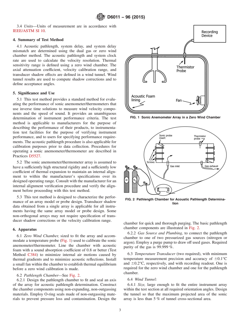
6.1 Zero Wind Chamber, sized to fit the array and accommodate a temperature probe (Fig. 1) used to calibrate the sonic
anemometer/thermometer. Line the chamber with acoustic foam with a sound absorption coefficient of 0.8 or better (Test Method
C384) to minimize internal air motions caused by thermal gradients and to minimize acoustic reflections. Install a small fan within
the chamber to establish thermal equilibrium before a zero wind calibration is made.
FIG. 1 Sonic Anemometer Array in a Zero Wind Chamber
D6011 − 96 (2015)
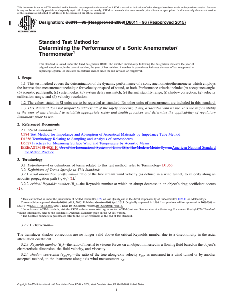
6.2 Pathlength Chamber—See Fig. 2.
6.2.1 Design the pathlength chamber to fit and seal an axis of the array for acoustic pathlength determination. Construct the
chamber components using non-expanding, non-outgassing materials. Employ O-ring seals made of non-outgassing materials to
prevent pressure loss and contamination. Design the chamber for quick and thorough purging. The basic pathlength chamber
components are illustrated in Fig. 2.
6.2.2 Gas Source and Plumbing, to connect the pathlength chamber to one of two pressurized gas sources (nitrogen or argon).
Employ a purge pump to draw off used gases. Required purity of the gas is 99.999 %.
6.3 Temperature Transducer (two required), with minimum temperature measurement precision and accuracy of 60.1°C and
60.2°C, respectively, and with recording readout. One is required for the zero wind chamber and one for the pathlength chamber.
6.4 Wind Tunnel:
6.4.1 Size, large enough to fit the entire instrument array within the test section at all required orientation angles. Design the
tunnel so that the maximum projected area of the sonic array is less than 5 % of tunnel cross-sectional area.
6.4.2 Speed Control, to vary the flow rate over a range of at least 1.0 to 10 m/s within 60.1 m/s or better throughout the test
section.
6.4.3 Calibration—Calibrate the mean flow rate using transfer standards traceable to the National Institute of Standards and
Technology (NIST), or by an equivalent fundamental physical method.
6.4.4 Turbulence, with a uniform velocity profile with a minimum of swirl at all speeds, and known uniform turbulence scale
and intensity throughout the test section.
6.4.5 Rotating Plate, to hold the sonic transducer array in varying orientations to achieve angular exposures up to 360°, as
needed. The minimum plate rotation requirements are 660° in the horizontal and 615° in the vertical, with an angular alignment
resolution of 0.5°.
NOTE 1—Design the plate to hold the array at chosen angles without disturbing the test section wind velocity profile or changing its turbulence level.
6.5 Measuring System:
6.5.1 Counter, to log the anemometer velocity component readings, with a count resolution equaling or exceeding the clock rate
of the sonic anemometer/thermometer.
6.5.2 R
...
Questions, Comments and Discussion
Ask us and Technical Secretary will try to provide an answer. You can facilitate discussion about the standard in here.