


prEN 18344
(Main)Execution of special geotechnical works - Artificial ground freezing
General Information
- Abstract
This document establishes general principles for the execution, testing and monitoring of Artificial Ground Freezing (AGF) works.
AGF is the process of changing the water in the ground from liquid to solid state in a controlled way by artificial means.
This document is applicable to:
— civil works (tunnels, shafts, retaining walls, plugs, underpinning …)
— environmental works (remediation, cut-off walls, …).
This document does not apply to:
— permafrost
— seasonal frost
— mining applications.
- Status
- Not Published
- Publication Date
- 06-Sep-2027
- Technical Committee
- CEN/TC 288 - Execution of special geotechnical works
- Drafting Committee
- CEN/TC 288/WG 20 - Ground freezing
- Current Stage
- 4060 - Closure of enquiry - Enquiry
- Start Date
- 23-Jul-2026
- Due Date
- 14-Jul-2026
- Completion Date
- 23-Jul-2026

Overview
prEN 18344: Execution of Special Geotechnical Works - Artificial Ground Freezing (AGF) is a draft European Standard developed by CEN/TC 288. This standard establishes the fundamental principles for the execution, testing, and monitoring of artificial ground freezing, a widely used temporary ground improvement method. AGF is a controlled process where the water in the ground is transformed from liquid to solid (ice) using artificial means, enhancing the ground's strength and impermeability.
prEN 18344 applies to:
- Civil engineering works, such as tunnels, shafts, retaining walls, plugs, and underpinning
- Environmental works, including remediation and cut-off walls
prEN 18344 does NOT apply to:
- Permafrost or seasonal frost conditions
- Mining applications
The standard provides requirements and recommendations for project planning, geotechnical investigation, material selection, execution, monitoring, and documentation for AGF works.
Key Topics
prEN 18344 addresses several essential aspects of artificial ground freezing:
- Scope and Information Requirements: Defines where AGF is applicable and outlines the information needed before execution, including project objectives, ground conditions, adjacent structures, and environmental constraints.
- Geotechnical Investigation: Specifies the necessary investigations to determine groundwater conditions, soil types, permeability, and the presence of obstructions, following EN 1997-2.
- Materials and Products: Lists requirements for water, cement, hydraulic binders, clay materials, admixtures, freezing pipes, coolants, insulation, and monitoring equipment.
- Design Considerations: Covers AGF system selection (closed, open, or combined circuits), structural and thermal design criteria, monitoring plans, and adaptation to site-specific requirements in accordance with EN 1997-1.
- Execution and Monitoring: Outlines best practices for installation of freeze pipes and plants, freezing operations, maintenance and thawing phases, tolerances, and monitoring protocols.
- Supervision, Inspection, and Testing: Recommends implementing a quality management system, including routine monitoring of freezing process, ground deformation, water pressure, and related reporting.
- Safety and Environmental Considerations: Highlights the importance of health & safety measures, environmental protection, and sustainability.
Applications
Artificial Ground Freezing based on prEN 18344 is utilized in a variety of ground engineering and environmental projects:
Civil Infrastructure:
- Creating watertight barriers for underground construction (tunnels and shafts)
- Stabilizing ground during foundation works or underpinning
- Temporary retaining walls and structural plugs
Environmental Projects:
- Remediation of contaminated sites
- Formation of cut-off walls to control groundwater flow and containment of pollutants
Key benefits of AGF:
- Temporary yet robust ground improvement where excavation or groundwater control is required
- Adaptable to a wide range of soil types and given site constraints
- Enables safe and effective construction in challenging ground or urban environments
Adhering to prEN 18344 ensures that such works are executed with a high level of safety, reliability, and compliance with European best practices.
Related Standards
prEN 18344 references and complements several established European standards and codes, including:
- EN 1997-1 (Eurocode 7): Geotechnical design - Part 1: General rules
- EN 1997-2 (Eurocode 7): Geotechnical design - Part 2: Ground properties
- EN 1990-1 (Eurocode): Basis of structural and geotechnical design
- EN 197-1: Cement - Composition, specifications, and conformity criteria
These standards offer foundational principles for geotechnical investigations, design, and quality assurance, ensuring artificial ground freezing works conform to recognized safety, performance, and documentation requirements across Europe.
Keywords: artificial ground freezing, AGF, geotechnical works, prEN 18344, CEN, ground improvement, underground construction, temporary ground support, European Standard, groundwater control, civil engineering, environmental remediation, freeze pipes, quality management.
Get Certified
Connect with accredited certification bodies for this standard

Zavod za gradbeništvo Slovenije (ZAG) - Inšpekcija
ZAG inspection body for construction products, structures, and materials.
Sponsored listings
Frequently Asked Questions
prEN 18344 is a draft published by the European Committee for Standardization (CEN). Its full title is "Execution of special geotechnical works - Artificial ground freezing". This standard covers: This document establishes general principles for the execution, testing and monitoring of Artificial Ground Freezing (AGF) works. AGF is the process of changing the water in the ground from liquid to solid state in a controlled way by artificial means. This document is applicable to: — civil works (tunnels, shafts, retaining walls, plugs, underpinning …) — environmental works (remediation, cut-off walls, …). This document does not apply to: — permafrost — seasonal frost — mining applications.
This document establishes general principles for the execution, testing and monitoring of Artificial Ground Freezing (AGF) works. AGF is the process of changing the water in the ground from liquid to solid state in a controlled way by artificial means. This document is applicable to: — civil works (tunnels, shafts, retaining walls, plugs, underpinning …) — environmental works (remediation, cut-off walls, …). This document does not apply to: — permafrost — seasonal frost — mining applications.
prEN 18344 is classified under the following ICS (International Classification for Standards) categories: 93.020 - Earthworks. Excavations. Foundation construction. Underground works. The ICS classification helps identify the subject area and facilitates finding related standards.
prEN 18344 is available in PDF format for immediate download after purchase. The document can be added to your cart and obtained through the secure checkout process. Digital delivery ensures instant access to the complete standard document.
Standards Content (Sample)
SLOVENSKI STANDARD
01-junij-2026
Izvedba posebnih geotehničnih del - Umetno zamrzovanje tal
Execution of special geotechnical works - Artificial ground freezing
Ausführung von Arbeiten im Spezialtiefbau - Künstliche Bodenvereisung
Exécution des travaux géotechniques spéciaux - Congélation artificielle des sols
Ta slovenski standard je istoveten z: prEN 18344
ICS:
93.020 Zemeljska dela. Izkopavanja. Earthworks. Excavations.
Gradnja temeljev. Dela pod Foundation construction.
zemljo Underground works
2003-01.Slovenski inštitut za standardizacijo. Razmnoževanje celote ali delov tega standarda ni dovoljeno.
DRAFT
EUROPEAN STANDARD
NORME EUROPÉENNE
EUROPÄISCHE NORM
April 2026
ICS 93.020
English Version
Execution of special geotechnical works - Artificial ground
freezing
Exécution des travaux géotechniques spéciaux - Ausführung von Arbeiten im Spezialtiefbau -
Congélation artificielle des sols Künstliche Bodenvereisung
This draft European Standard is submitted to CEN members for enquiry. It has been drawn up by the Technical Committee
CEN/TC 288.
If this draft becomes a European Standard, CEN members are bound to comply with the CEN/CENELEC Internal Regulations
which stipulate the conditions for giving this European Standard the status of a national standard without any alteration.
This draft European Standard was established by CEN in three official versions (English, French, German). A version in any other
language made by translation under the responsibility of a CEN member into its own language and notified to the CEN-CENELEC
Management Centre has the same status as the official versions.
CEN members are the national standards bodies of Austria, Belgium, Bulgaria, Croatia, Cyprus, Czech Republic, Denmark, Estonia,
Finland, France, Germany, Greece, Hungary, Iceland, Ireland, Italy, Latvia, Lithuania, Luxembourg, Malta, Netherlands, Norway,
Poland, Portugal, Republic of North Macedonia, Romania, Serbia, Slovakia, Slovenia, Spain, Sweden, Switzerland, Türkiye and
United Kingdom.
Recipients of this draft are invited to submit, with their comments, notification of any relevant patent rights of which they are
aware and to provide supporting documentation.
Warning : This document is not a European Standard. It is distributed for review and comments. It is subject to change without
notice and shall not be referred to as a European Standard.
EUROPEAN COMMITTEE FOR STANDARDIZATION
COMITÉ EUROPÉEN DE NORMALISATION
EUROPÄISCHES KOMITEE FÜR NORMUNG
CEN-CENELEC Management Centre: Rue de la Science 23, B-1040 Brussels
© 2026 CEN All rights of exploitation in any form and by any means reserved Ref. No. prEN 18344:2026 E
worldwide for CEN national Members.
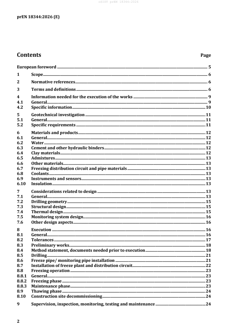
Contents Page
European foreword . 5
1 Scope . 6
2 Normative references . 6
3 Terms and definitions . 6
4 Information needed for the execution of the works . 9
4.1 General. 9
4.2 Specific information . 10
5 Geotechnical investigation . 11
5.1 General. 11
5.2 Specific requirements . 11
6 Materials and products . 12
6.1 General. 12
6.2 Water . 12
6.3 Cement and other hydraulic binders . 12
6.4 Clay materials . 12
6.5 Admixtures . 13
6.6 Other materials . 13
6.7 Freezing distribution circuit and pipe materials . 13
6.8 Coolants . 13
6.9 Instruments and sensors . 13
6.10 Insulation . 13
7 Considerations related to design . 13
7.1 General. 13
7.2 Drilling geometry . 15
7.3 Structural design . 15
7.4 Thermal design . 15
7.5 Monitoring system design. 16
7.6 Other design aspects . 16
8 Execution . 16
8.1 General. 16
8.2 Tolerances . 17
8.3 Preliminary works. 18
8.4 Method statement, documents needed prior to execution . 18
8.5 Drilling . 21
8.6 Freeze pipe/ monitoring pipe installation . 21
8.7 Installation of freeze plant and distribution circuit . 22
8.8 Freezing operation . 23
8.8.1 General. 23
8.8.2 Freezing phase . 23
8.8.3 Maintenance phase . 23
8.9 Thawing phase . 24
8.10 Construction site decommissioning . 24
9 Supervision, inspection, monitoring, testing and maintenance . 24
9.1 General . 24
9.2 Drilling and freeze / temperature monitoring pipe installation . 24
9.3 Installation of freezing plant and distribution circuit . 25
9.4 Freezing operation . 25
9.4.1 Monitoring of freeze system . 25
9.4.2 Monitoring of frozen ground body development . 25
9.4.3 Monitoring of water pressure/level . 25
9.4.4 Monitoring of induced displacements . 26
9.4.5 Additional monitoring . 26
10 Record . 26
10.1 Documents to be available on site . 26
10.2 Documents recommended to be on site . 26
10.3 Documents to be produced on site . 26
10.3.1 Drilling reporting . 26
10.3.2 Freezing system installation reporting . 27
10.3.3 AGF monitoring reporting . 27
10.3.4 Water pressure/level monitoring reporting . 27
10.3.5 Displacement monitoring reporting . 27
11 Special requirements . 27
11.1 General . 27
11.2 Health and Safety . 28
11.3 Environmental aspects . 29
11.4 Sustainability . 29
11.5 Impact of adjacent structure . 30
Annex A (informative) Freeze systems . 31
A.1 Freeze system, closed circuit . 31
A.2 Freeze system, open circuit. 32
Annex B (informative) Considerations related to design of the AGF works and resulting laboratory
test program . 33
B.1 General approach . 33
B.2 Parameters . 33
B.3 Structural design. 34
B.4 Thermal design . 34
B.5 Required laboratory test program for structural and watertightness design . 35
B.6 Required laboratory test program for thermal design . 36
Annex C (informative) Commonly used models for structural design . 37
C.1 General approach . 37
C.2 Modelling approach according to Klein . 38
C.3 Modelling approach according to Orth . 39
Annex D (informative) Points of attention . 41
D.1 General . 41
D.2 Pressure relief pipes. 41
D.3 Settlements induced by de-structuration of clay . 41
D.4 Low moisture content . 41
D.5 Sealing AGF to other structures . 41
D.6 Over freezing . 42
D.7 Significant groundwater velocity . 42
D.8 Influence of heat sources . 42
D.9 Excavation in contact with AGF wall . 42
Annex E (informative) Typical pressure for testing freeze pipes, freeze heads and distribution
circuit . 43
E.1 Maximum system operating pressure (MSOP) . 43
E.2 Testing pressure. 44
E.2.1 General. 44
E.2.2 Freeze pipes testing pressure . 44
E.2.3 Distribution circuit and freeze heads . 45
E.3 Pressure test procedure . 45
Bibliography . 46
European foreword
This document (prEN 18344:2026) has been prepared by Technical Committee CEN/TC 288 “Execution
of special geotechnical work”, the secretariat of which is held by AFNOR.
This document is currently submitted to the CEN Enquiry.
This document has been prepared under a Standardization Request given to CEN by the European
Commission and the European Free Trade Association, and supports essential requirements of
EU Directive(s) / Regulation(s).
1 Scope
This document establishes general principles for the execution, testing and monitoring of Artificial
Ground Freezing (AGF) works.
AGF is the process of changing the water in the ground from liquid to solid state in a controlled way by
artificial means.
This document is applicable to:
— civil works (tunnels, shafts, retaining walls, plugs, underpinning, …);
— environmental works (remediation, cut-off walls, …).
This document does not apply to:
— permafrost;
— seasonal frost;
— mining applications.
2 Normative references
The following documents are referred to in the text in such a way that some or all of their content
constitutes requirements of this document. For dated references, only the edition cited applies. For
undated references, the latest edition of the referenced document (including any amendments) applies.
EN 1990-1, Eurocode — Basis of structural and geotechnical design — Part 1: New structures
EN 1997-1, Eurocode 7 — Geotechnical design — Part 1: General rules
EN 1997-2, Eurocode 7 — Geotechnical design — Part 2: Ground properties
EN 197-1, Cement — Part 1: Composition, specifications and conformity criteria for common cements
3 Terms and definitions
For the purposes of this document, the following terms and definitions apply.
ISO and IEC maintain terminology databases for use in standardization at the following addresses:
— ISO Online browsing platform: available at https://www.iso.org/obp/
— IEC Electropedia: available at https://www.electropedia.org/
3.1
artificial ground freezing (AGF)
ground improvement technique consisting in extracting heat from any kind of ground, to temporarily
change the pore water from liquid to solid state
Note 1 to entry: The aim is to achieve impermeability and/or to improve the mechanical properties of the ground.
Note 2 to entry: This freezing process is reversible. However, after thawing initial ground parameters could be
affected.
Note 3 to entry: AGF works include all ancillary activities needed for the execution of AGF (e.g. drillings).
3.2
coolant
fluid used to extract heat from the ground (e.g. brine, liquid nitrogen, glycol, carbon dioxide)
3.3
cryogenic fluid
liquified gases at very low temperature that are used as coolant
3.4
distribution circuit
circuit distributing the coolant from the freeze plant to the freeze pipes through the freeze heads
Note 1 to entry: It consists of a supply line (feeding line) and a return line.
Note 2 to entry: While for closed circuit the return line is connected to the freeze plant, for open circuit it is open
to the atmosphere (exhaust line).
Note 3 to entry: For more information, see Annex A.
3.5
freeze design criteria
shape, thickness, temperature of the frozen ground to be achieved according to the design
3.6
freeze head
connection device installed between the distribution circuit and the freeze pipes
Note 1 to entry: For more information, see Annex A.
3.7
freeze pipe
pipe installed in the ground, allowing the flow of the coolant to exchange heat with the ground
Note 1 to entry: “freeze probe” or “freeze lance” are terms admitted instead of “freeze pipe”.
3.8
freeze plant
part of a freeze system capable to supply the cold coolant necessary to freeze the ground in a closed or
open circuit
Note 1 to entry: The freeze plant is connected to the distribution circuit.
3.9
freeze system
system capable of freezing the ground using a closed or open circuit. Sum of freeze plant, distribution
circuit, freeze heads and freeze pipes
3.10
freeze unit
unitary equipment able to lower the temperature of a coolant
Note 1 to entry: In a closed circuit freeze system it is part of the freeze plant.
Note 2 to entry: “chiller” is a term admitted instead of “freeze unit”.
3.11
freezing, closed circuit
(indirect method)
freezing method where the coolant is re-used in a closed loop after heat exchange with the ground
Note 1 to entry: After this heat exchange, the temperature of the coolant is lowered again passing through the
freeze unit, where a refrigerant is used.
3.12
freezing, open circuit
(direct method)
freezing method where the coolant is released to the atmosphere as a gas after heat exchange with the
ground
3.13
freezing, combined method
freezing method where both open circuit and closed circuit methods are used, either at the same time, or
in different phases
3.14
freezing phase
(freezing-up)
working phase where the frozen ground body grows until reaching the freeze design criteria
3.15
frost creep
increase in strain in the frozen ground body at constant effective stress during all AGF phases
Note 1 to entry: The creep depends on time, temperature, stress and ground type.
3.16
frost heave
swelling of ground due to the formation of ice caused by AGF
Note 1 to entry: That includes the formation of ice lenses at the freezing front as well as volumetric expansion due
to phase change.
Note 2 to entry: Frost heave can affect ground surface and objects, on or in the ground.
3.17
frost pressure
positive pressure developed at ice-water interface in a ground as it freezes
3.18
frozen ground body
volume of frozen ground formed by means of AGF
3.19
maintenance phase
phase in the AGF process, following the freezing phase, during which the frozen ground body is
maintained according to the freeze design criteria
3.20
monitoring system
system consisting of sensors and data acquisition system to monitor AGF and its effects
3.21
pressure test
test performed on the distribution circuit and freeze pipes to check their tightness
Note 1 to entry: Test pressure (TP) depends on the maximum system operating pressure (MSOP).
Note 2 to entry: For more information, see Annex E.
3.22
refrigerant
fluid circulating in the freeze unit to allow lowering the temperature of the coolant
Note 1 to entry: Refrigerant can also be used as a coolant.
Note 2 to entry: “cooling agent” is a term admitted instead of “refrigerant”.
3.23
thawing phase
phase in the AGF process, following the maintenance phase, when heat extraction has been definitively
stopped
3.24
thaw deformation
deformation of the ground resulting from thawing of frozen ground body
4 Information needed for the execution of the works
4.1 General
Prior to the execution of the work, all necessary information shall be made available.
This information should include, where relevant:
— any legal or statutory restrictions (e.g. permissions for working and deliveries 24/7, setup and
operation of a storage tank for cryogenic fluid);
— the locations and conditions of structures, roads, services, etc. adjacent to the work, including any
necessary surveys;
— previous use of the site;
— the geometry of the site (boundary conditions, topography, access, slopes, etc.);
— available space for site installations and storage;
— headroom restrictions and confined spaces;
— geotechnical information and data as specified in Clause 5;
— presence of obstructions in the ground (underground structures, services old masonry, anchors,
concrete, blocks and boulders, etc.);
— presence of natural and/or manmade cavities (caverns, mines, large voids, discontinuities and
cracks, etc.);
— archaeological remains;
— possible presence of unexploded ordnance;
— the environmental restrictions, including noise, vibration, pollution;
— and all other information that may influence the execution.
4.2 Specific information
4.2.1 The specific information should cover, when relevant:
— objectives of AGF (impermeability and/or structural purposes);
— geotechnical and hydrogeotechnical information and date as specified in Clause 5;
— design report including mechanical and thermal analysis;
— need of a preliminary ground treatment;
— need of a specific AGF method;
— the location of main grid lines for setting out drilling positions;
— technical specifications;
— adjacent structures (types, loads, and geometry) and, sensitivity to movement and/or low
temperatures;
— presence of utilities (cables, pipes, sewers, etc.) and sensitivity to movement and/or low
temperatures;
— presence of polluted ground, type, extent and degree of pollution and possible presence of anything
that may impact the freezing point;
— presence of products introduced into the ground (e.g. chemicals, insulating materials, foams) which
could have a detrimental impact on AGF;
— any specific requirements for AGF works, in particular those pertaining to tolerances, quality of
materials, methods and frequency of testing;
— where available, previous experience with freezing works on or adjacent to the site;
— proposed adjacent enabling or advance works that may affect the AGF works (e.g. dewatering works,
excavation works and tunnelling);
— presence of any kind of heat source in the proximity of the ground to be frozen (e.g. heated buildings,
district heating lines, sewers, energy piles);
— requirements for instrumentation and monitoring of potentially affected structures;
— a suitable quality management system, including supervision, inspection, monitoring and
maintenance.
4.2.2 Necessity, extent, procedure and content for any survey on the conditions of structure, roads,
services, grid lines, etc. adjacent to the works area shall be established.
4.2.3 Where relevant, thresholds values for any movement which may affect adjacent structures shall
be provided.
4.2.4 Any additional or deviating requirement shall be established before the commencement of the
AGF works and the quality control system shall be suitably amended.
NOTE Such additional or deviating requirements can be e.g.:
— reduced or increased geometrical construction deviations;
— application of different or varying materials;
— change of AGF method;
— installation of drilled elements in the frozen ground body;
— specific design requirements or technical specifications.
5 Geotechnical investigation
5.1 General
5.1.1 Any ground investigation shall fulfil the requirements of EN 1997-2 and the relevant national
documents.
5.1.2 The depth and the extent of the geotechnical investigation should be sufficient to identify all
ground formations and layers affected by the AGF works, to determine the relevant properties of the
ground and the ground conditions.
5.1.3 Relevant experience of the execution of comparable AGF works under similar conditions and/or
in the vicinity of the site should be considered in order to define the extent of the investigation program.
5.1.4 The ground investigation report shall be available and sufficient, to allow for reliable structural
and thermal design and execution of the AGF works.
5.1.5 The sufficiency of the geotechnical investigation for the design and execution of the AGF works
shall be verified also considering earlier geotechnical site investigations nearby.
5.1.6 If the geotechnical investigations are not sufficient, a supplementary investigation shall be
conducted.
5.2 Specific requirements
5.2.1 Particular attention shall be paid to the following aspects, which are relevant to the execution of
AGF works:
— piezometric levels and their variations versus time, permeability and water content of the different
layers;
— artesian conditions;
— groundwater flow conditions;
— highly permeable grounds or cavities (natural or artificial);
— ground and groundwater temperatures;
— presence of cohesive, fine grained and otherwise frost sensitive types of ground;
— chemistry and salinity of groundwater;
— presence of pre-treated ground;
— presence of rock, boulders, or obstructions or heterogenous ground which may require the use of
special drilling techniques.
NOTE 1 In order to choose suitable work methods, not only the average of ground properties but also their
distribution are relevant.
NOTE 2 Specific laboratory tests on frozen samples require more time than geotechnical laboratory tests on
unfrozen ground samples.
5.2.2 If the frozen ground body serves as a structural element and no relevant experiences of
comparable AGF works under similar conditions are available, specific laboratory tests should be
performed on frozen ground samples from the relevant ground layers. The required laboratory test
program is listed in Table B.1 and Table B.2 of Annex B.
6 Materials and products
6.1 General
6.1.1 The constituents shall meet the requirements set in the respective European Standards, the
provisions valid in the place of use and the provisions given in the project specification.
6.1.2 The sources of supply for materials and products shall be documented and shall not be changed
without prior notification of the involved parties.
6.2 Water
Unless potable water is used, its chemical suitability shall be verified (e.g. for grout, brine, freeze unit,
artificial ground saturation).
6.3 Cement and other hydraulic binders
6.3.1 Unless cement that complies with EN 197-1 is used, its suitability shall be verified for the purpose
envisaged.
6.3.2 Hydraulic binders other than cement may be used when the required performance is proven by
tests or respective regulations, certificates or approvals, according to the purpose envisaged.
6.4 Clay materials
6.4.1 Natural clays activated or modified bentonites may be used in drilling fluids and/or in binder-
based grouts.
6.4.2 Possible detrimental effect resulting from the use of clay materials should be evaluated.
6.5 Admixtures
6.5.1 Admixtures may be used for the preparation of the grout mixtures.
6.5.2 Possible detrimental effect resulting from the use of the admixture should be evaluated.
6.6 Other materials
6.6.1 For specific operations (e.g. sealing, filling voids, filling of pipes, …) other materials (e.g. sands,
fly-ash, silica fume, chemicals) may be used.
6.6.2 The required performance should be proven by tests or respective regulations, certificates or
approvals, according to the purpose envisaged.
6.7 Freezing distribution circuit and pipe materials
6.7.1 For the execution of the distribution circuit and pipes, the materials used shall comply with the
execution design and Clause 7.
6.7.2 Materials should comply with the loads, pressure, temperature range and duration needed and
all chemicals acting on them should be considered.
6.8 Coolants
6.7.1 For the execution of AGF works, the coolants used shall comply with the execution design and
Clause 7.
6.7.2 Coolants shall comply with the temperature range needed.
6.7.3 Coolants shall comply with the national environmental and safety standards.
6.9 Instruments and sensors
6.8.1 All the instrumentation and related sensors used for the monitoring of AGF works shall comply
with the execution design and Clause 7.
6.8.2 Instrumentation and related sensors shall comply with the temperature range and tolerance
needed.
6.10 Insulation
6.9.1 Insulating products used for the execution of AGF works shall comply with the execution design
and Clause 7.
6.9.2 Insulating products shall maintain the required thermal conductivity during the needed phases.
7 Considerations related to design
7.1 General
7.1.1 The basic standard for the design of ground improvement is EN 1997-1.
NOTE See Annex B and Annex C for additional information.
7.1.2 AGF is applied as temporary works for different purposes:
— to create impermeable frozen ground body;
— to create structural frozen ground body;
— a combination of both.
7.1.3 The boundary of the frozen ground body should be related to an isotherm that is at least 2 °C
below the freezing point of the groundwater.
7.1.4 The design for an impermeable function only requires thermal design for the frozen ground body.
7.1.5 The design for a structural function requires structural and thermal design for the frozen ground
body.
7.1.6 The design of a frozen ground body shall specify the following:
— the AGF method (closed circuit, open circuit or combined method);
— the required geometry;
— temperature requirements;
— time requirements;
— the related pipes lay-out;
— the monitoring requirements;
— where relevant, pore water pressure handling.
7.1.7 The design shall take into account site conditions and characteristics that may affect AGF works.
For example:
— working sequences;
— general methods;
— specific methods concerning the excavation under AGF conditions;
— pre-grouting;
— dewatering;
— watering;
— energy storage.
7.1.8 The detailed execution sequence should be shown on the execution drawings and/or models,
where relevant.
7.1.9 Governing design parameters depend on the purpose of AGF works.
7.1.10 The design shall provide an adequate monitoring program considering that the execution of AGF
works is based on the observational method, according to EC7.
7.2 Drilling geometry
7.2.1 Drilling tolerances and their potential effects shall be considered in the design.
7.2.2 The design shall consider the method of drilling and the construction tolerances set out in 8.2.
NOTE 1 Directional drilling are usually considered for long and curved drillings, critical ground conditions and
high precision requirements.
NOTE 2 Site constraints such as available operational space, ground conditions, obstructions, possibility of extra
drillings, etc. are key points for defining drilling tolerances.
7.2.3 The as-built path of boreholes shall be measured with sufficient accuracy. In case tolerances are
not met, the impact on the design shall be analysed taking into account the as-built geometry.
NOTE The method used for the measurement of the boreholes depends on the lengths of the drillings and
ground conditions.
7.2.4 The level of accuracy of measurements shall be defined by the design.
7.2.5 Instead of the path of the boreholes, the readily installed freeze/monitoring pipes may be
measured.
7.3 Structural design
The objective of the structural design is to determine the required frozen ground body thickness and its
related geomechanical properties, dependent on its temperature and duration of the maintenance phase.
7.4 Thermal design
7.4.1 The objective of the thermal design is to determine the freeze pipe pattern, freezing phase
duration and energy to be extracted to:
— achieve watertightness, if an impermeable frozen ground body is required;
— meet the requirements of structural design, if the frozen ground body serves as a structural element;
— meet the requirements of structural design and achieve watertightness, for the combination of both
functions.
7.4.2 The thermal design is an interacting process with the structural design (where relevant) and the
execution design: It forms the basis to determine the AGF works.
7.4.3 The thermal design should provide at least the following information:
— estimated duration of freezing phase(freezing-up);
— estimated power (energy) versus time as basis for freeze plant capacity / cryogenic fluid
consumption;
— estimated time- dependent temperature distribution within the frozen ground body;
— where relevant, specifications of insulation needed.
7.5 Monitoring system design
The design shall specify the monitoring and control criteria to be implemented before, during and after
the AGF.
7.6 Other design aspects
7.6.1 The design shall consider the possible effects on the ground (unfrozen/frozen) and nearby
structures by:
— freezing temperatures;
— frost heave;
— frost pressure;
— thaw deformations;
— excess of pore pressure in confined area;
— and where relevant provide mitigation measures.
7.6.2 The design shall consider the possible effects of freeze pipes installation through permanent
structures.
8 Execution
8.1 General
8.1.1 AGF can be carried out according to two different methods:
— closed up circuit (indirect method);
— open circuit (direct method).
The two methods can also be combined.
8.1.2 It is assumed that reasonable skill and care appropriate to the circumstances was exercised in the
design and execution planning.
8.1.3 It is assumed that the execution is made by appropriately qualified and experienced personnel.
8.1.4 If the observation made during execution indicate significant differences from the design
assumptions, then the reason for the deviation should be investigated and the freezing process adjusted.
NOTE Significant differences can be in (but are not limited to):
— geotechnical conditions;
— ground water velocity;
— ground water temperature;
— salinity;
— saturation index;
— pollution (e.g. mineral oil or chemical products in the ground including groundwater);
— changes in construction works and/or schedule.
8.1.5 All relevant parties shall participate in the decision when execution design adjustments are made.
8.1.6 The phases of execution usually consist of:
— drilling of freeze pipes and monitoring pipes;
— drilling of pressure relief pipes, where needed;
— freeze pipe and monitoring pipe installation;
— pressure relief pipe installation, where needed;
— installation of freeze plant and distribution circuit and testing;
— installation of monitoring system (e.g. for ground temperatures, plant data, displacement of existing
structures, pressure of water and water flow where needed);
— freezing phase;
— maintenance phase;
— thawing phase;
— decommissioning and dismantling (it can overlap with the thawing phase).
8.1.7 Recommendations for subsequent works carried out under protection of or near AGF works.
8.1.8 The presence of AGF works can affect other works in the vicinity and vice versa (e.g. excavation,
tunnelling, concrete works, drilling works ETC). The following aspects shall be considered as a minimum:
— heat from excavation activities (e.g. convection along newly exposed surface, excavation equipment);
— heat from the hydrating of binder;
— damage to the freeze pipes (e.g. by over-excavation), the distribution circuit or other parts of the
freeze system;
— choice of the excavation tools and methods in order to minimize vibrations;
— mechanical properties of the frozen ground body in terms of excavation tools and methods;
— over-excavation as a structural risk;
— frost pressure to existing structures (e.g. foundations, tunnels, retaining structures, sewers).
8.2 Tolerances
8.2.1 Unless otherwise specified, the location of the starting point of drilling should be installed
within ± 0,05 m of tolerance.
8.2.2 Unless otherwise specified, drilling tolerance for AGF boreholes should consider typically 2 % of
deviation of the design length of the borehole.
8.2.3 The choice of drilling method should allow for as little deviation as possible.
8.3 Preliminary works
8.3.1 The preparation shall be carried out in accordance with the design specifications and the specific
site conditions.
8.3.2 Working platform
8.3.2.1 Working platform shall be suitable for the safe operation of heavy equipment and any other
site activity including deliveries.
8.3.2.2 Working platform shall be of sufficient dimensions and where relevant above the water table
and levelled horizontally.
8.3.2.3 Material used for the construction and maintenance of the working platform shall comply
with the specified requirements.
8.3.2.4 The working platform, the access (e.g. ramps, stairs) shall be maintained such that they
remain functional.
8.3.3 Working areas
8.3.3.1 The working area shall provide sufficient space for the installation (including protection
areas), supply and return lines and storage of materials.
8.3.3.2 The working area shall provide possibility to carry out emergency repair or replacement of
machinery.
8.3.4 The materials delivered on site shall be protected from any environmental impact that could
otherwise detrimentally affect its use and/or performance.
8.3.5 The collection and disposal of the drilling backflow shall be taken into consideration.
8.4 Method statement, documents needed prior to execution
8.4.1 Before starting the AGF works, method statements shall be prepared.
8.4.2 These method stateme
...